EP1297776A2 - Vorrichtung zur Steuerung eines elektrischen Gerätes - Google Patents
Vorrichtung zur Steuerung eines elektrischen Gerätes Download PDFInfo
- Publication number
- EP1297776A2 EP1297776A2 EP02020966A EP02020966A EP1297776A2 EP 1297776 A2 EP1297776 A2 EP 1297776A2 EP 02020966 A EP02020966 A EP 02020966A EP 02020966 A EP02020966 A EP 02020966A EP 1297776 A2 EP1297776 A2 EP 1297776A2
- Authority
- EP
- European Patent Office
- Prior art keywords
- designed
- slider
- handle
- hand
- user
- Prior art date
- Legal status (The legal status is an assumption and is not a legal conclusion. Google has not performed a legal analysis and makes no representation as to the accuracy of the status listed.)
- Withdrawn
Links
Images


Classifications
-
- A—HUMAN NECESSITIES
- A47—FURNITURE; DOMESTIC ARTICLES OR APPLIANCES; COFFEE MILLS; SPICE MILLS; SUCTION CLEANERS IN GENERAL
- A47L—DOMESTIC WASHING OR CLEANING; SUCTION CLEANERS IN GENERAL
- A47L9/00—Details or accessories of suction cleaners, e.g. mechanical means for controlling the suction or for effecting pulsating action; Storing devices specially adapted to suction cleaners or parts thereof; Carrying-vehicles specially adapted for suction cleaners
- A47L9/28—Installation of the electric equipment, e.g. adaptation or attachment to the suction cleaner; Controlling suction cleaners by electric means
- A47L9/2857—User input or output elements for control, e.g. buttons, switches or displays
-
- A—HUMAN NECESSITIES
- A47—FURNITURE; DOMESTIC ARTICLES OR APPLIANCES; COFFEE MILLS; SPICE MILLS; SUCTION CLEANERS IN GENERAL
- A47L—DOMESTIC WASHING OR CLEANING; SUCTION CLEANERS IN GENERAL
- A47L9/00—Details or accessories of suction cleaners, e.g. mechanical means for controlling the suction or for effecting pulsating action; Storing devices specially adapted to suction cleaners or parts thereof; Carrying-vehicles specially adapted for suction cleaners
- A47L9/28—Installation of the electric equipment, e.g. adaptation or attachment to the suction cleaner; Controlling suction cleaners by electric means
- A47L9/2836—Installation of the electric equipment, e.g. adaptation or attachment to the suction cleaner; Controlling suction cleaners by electric means characterised by the parts which are controlled
-
- A—HUMAN NECESSITIES
- A47—FURNITURE; DOMESTIC ARTICLES OR APPLIANCES; COFFEE MILLS; SPICE MILLS; SUCTION CLEANERS IN GENERAL
- A47L—DOMESTIC WASHING OR CLEANING; SUCTION CLEANERS IN GENERAL
- A47L9/00—Details or accessories of suction cleaners, e.g. mechanical means for controlling the suction or for effecting pulsating action; Storing devices specially adapted to suction cleaners or parts thereof; Carrying-vehicles specially adapted for suction cleaners
- A47L9/32—Handles
Definitions
- the present invention relates to a device for controlling an electrical Device, in particular for controlling electrically or electronically operated Functional parts of a floor care device or a similar household appliance, the is designed such that it is either carried by hand by a user or is performed, the device being arranged on a handle.
- a device accordingly provides that a slider is located in the trained substantially over the entire surface of the handle and is designed to be displaceable at least in an area in which the slider is moved a hand and / or a finger of a user for setting and / or moving is achievable.
- the realized according to the invention and subsequently by features and technical measures according to the Sub-claims still improved wide adjustment range creates the possibility of a Adjust engine power in a short time with purely intuitive handling.
- Such a thing Regulating or adjusting is also essentially over an entire handle length and also possible in every grip position or hand position, since there is always at least one finger of the User is in the immediate vicinity or even on the slider.
- the slider has elongated sliding element.
- One surface of the sliding element is for one hand and / or a finger of a user is designed to be non-slip.
- the sliding element preferably slidably held in a guide rail which in runs essentially in the direction of a longitudinal axis of the handle. That's the way it is Slider over the sliding element as a whole over another area of the Handle for a user to operate and carry out safely and comfortably to postpone a shot.
- the sliding element is slidable and flexible Connection element for transmitting a displacement movement to an electrical, electronic and / or mechanical control element connected.
- One is in particular integral connection of these parts is provided.
- the actuating element as an element of the actual conversion of the mechanical displacement with the coupled one Changing the path into an electrical signal is particularly useful as a slide potentiometer educated.
- the handle on the household appliance is preferably ergonomically shaped and pleasant feel, preferably also designed to be non-slip.
- There is one Device according to the invention preferably as part of the handle in the form of a Hose handle designed for a vacuum cleaner.
- An inventive The device is then designed in particular for setting an engine power, wherein the slider over its large or wide adjustment range as reliable and exact setting preferably from a shutdown to a maximum Motor suction power of the cylinder vacuum cleaner is designed.
- the guide rail is compared to one the sliding element has a soft surface and has a haptically pleasant feel Design on.
- the guide rail thus creates a tactile feel Contrast to the sliding element, so that a device according to the invention already can be handled blindly and / or intuitively after a very short familiarization phase can.
- the slider is at least in Area of a rest position for influencing the control of an electrical one Additional function of the household appliance trained.
- known devices especially at Vacuum cleaners must still be the actual vacuum cleaner operation today Regardless of the operation of a header or down be switched off. As a result, multiple operations are always necessary.
- the Use, for example, of a front sweeper with minimal suction power of the Vacuum cleaner almost nonsensical, because dissolved protective particles and dust parts in it Operating state then only whirled up, but not sucked away. It can be so As a result of the incorrect operation described, dust may develop which the actual sense of vacuuming runs counter to it. It is therefore preferred that the Slider in a rest position to switch off an additional electrical function of the household appliance is designed.
- the slider is in its rest position Effect an interruption in the power supply of an additional electrical function of the household appliance trained.
- the slider is preferably in the rest position for switching off an electric motor-operated brush or brush sweeper educated.
- there is an interrupter switch provided that with the sliding element or to the sliding element is mechanically coupled.
- a backdrop that is particularly movable is used for the stated purpose.
- a switchable power connection is preferably provided in the area of the device, that for connecting an attachment and / or other external additional functions is trained.
- a switch is a hand of a user provided facing.
- the switch is preferably a toggle switch executed.
- the slider or that Sliding potentiometer is preferably perpendicular to a longitudinal axis of the handle slidably aligned.
- a device thus creates with optional implementation above features a way for an easy to use Power adjustment with just one hand on an ergonomically shaped handle. A change of grip is no longer necessary to actuate operating elements.
- a device according to the invention builds thereby on the use of a so-called Incord remote control on, i.e. a controller that Control and / or supply lines for electrical energy through a suction hose from the vacuum cleaner housing to the handle.
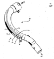
- a device 1 according to the invention is shown in the sketched illustration in FIG a first embodiment in a three-dimensional view as part of a handle H shown.
- the handle H is a hose handle for one not shown Canister vacuum cleaner and accordingly between an approach for one Suction hose S and a coupling piece R for a pipe and / or attachments arranged.
- the hose handle is hollow or tubular as a plastic injection molded part educated.
- the device 1 comprises a slider or slider 2, from which here For reasons of clarity, only one can be moved in a guide rail 3 held sliding element 4 are shown with a driver 6, the Driver 6 shown mechanically coupled via a flexible connecting element 5 is.
- This structure makes it more coordinated using one another Plastics created a durable device 1 which in the direction of a longitudinal axis M of the handle H over an entire length and in each handle position of one hand is operable.
- a particularly to secure a set position of the Slider 2 against accidental slipping is desired low friction adjustable between the moving parts.
- By ordering the Sliding element 4 on an upper side O of the handle H is advantageously ensures that in normal hand position at least one thumb or index finger an operator ready to intervene at any time in direct contact with the Slider 2 stands.
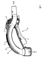
- Figure 2 completes a view of the handle of Figure 1 in one mounted and around a container C for receiving an attachment, a nozzle etc. extended form.
- a housing G is above the area of the driver 6 arranged.
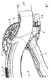
- Figure 3 is a sectional view of the embodiment shown in Figure 2 in a three-dimensional view, in which a very compact interior of the completely assembled housing G can be seen.
- one area is the Top side O of the handle H through a knob structure N from the sliding element 4 also optically set off. This difference is supported by a special choice of the respective material on the surface, also felt in a pleasant way. So that is with an operation of the slider 2 always correct operation even blind or without previous or accompanying searches guaranteed through intuitive handling.
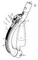
- FIG. 4 shows an enlarged one Sectional view of a detail of the view of Figure 3 showing an inner Construction of an extended control on the handle H.
- the extension of the handle H relates to the housing G in particular a slider V, via which only one indicated current connection A for external devices or not shown Attachments can be switched.
- An actuating element 8 is advantageously for the Slider 2 in the form of a slide potentiometer arranged so that it is in a Off position also interrupts the energy supply of the slider V. The happens regardless of the switching position of the slider V.
- next to switching off also switching on electrically controlled attachment nozzles and / or Attachments automatically in the case by canceling the interruption of the Energy supply causes, a default setting in particular the slider V preserved.
- this arrangement for actuation in the form of a Switching on or off saves at least one operating step.
- Figure 5 is a sectional view of another embodiment of a handle H in a three-dimensional view.
- the slider V is perpendicular to that Longitudinal axis M of the handle H slidably on a rocker W of a toggle switch arranged.
- the existing described combination of the effect of slider 2 and slider V in one The standby position is retained.
- FIG. 6 shows an enlarged sectional illustration of a detail of the top view of FIG 5 showing an internal structure of the extended control device 1 various functions of the vacuum cleaner on the handle H.
Landscapes
- Engineering & Computer Science (AREA)
- Mechanical Engineering (AREA)
- Electric Vacuum Cleaner (AREA)
- Central Heating Systems (AREA)
Abstract
Description
- Figur 1:
- eine skizzierte Darstellung einer dreidimensionalen Ansicht eines Handgriffs mit einem Schieberegler in einer ersten Ausführungsform;
- Figur 2:
- eine Ansicht des Handgriffs von Figur 1 in einem fertig montierten und um einen Container zur Aufnahme von Vorsatzgeräten erweiterten Form;
- Figur 3:
- eine Schnittdarstellung der Ausführungsform gemäß Abbildung von Figur 2 in einer dreidimensionalen Ansicht;
- Figur 4:
- eine vergrößerte Schnittdarstellung einer Einzelheit der Ansicht von Figur 3 mit Darstellung eines inneren Aufbaus einer erweiterten Steuerung an dem Handgriff;
- Figur 5:
- eine Schnittdarstellung einer weiteren Ausführungsform eines Handgriffs in einer dreidimensionalen Ansicht und
- Figur 6:
- eine vergrößerte Schnittdarstellung einer Einzelheit der Draufsicht von Figur 5 mit Darstellung eines inneren Aufbaus einer nochmals erweiterten Steuerung an dem Handgriff.
Claims (18)
- Vorrichtung zur Steuerung eines elektrischen Gerätes, insbesondere zur Ansteuerung elektrisch oder elektronisch bedienbarer Funktionsteile eines Bodenpflegegerätes oder eines ähnlichen Haushaltgerätes, das derart ausgebildet ist, dass es entweder von einem Benutzer per Hand getragen oder geführt wird, wobei die Vorrichtung an einem Handgriff angeordnet ist
dadurch gekennzeichnet, dass ein Schieberegler (2) sich im wesentlichen über die gesamte Oberfläche des Handgriffs (H) erstreckend ausgebildet und
mindestens in einem Bereich verschieblich ausgeführt ist, in dem der Schieberegler (2) durch eine Hand und/oder einen Finger eines Anwenders zum Einstellen und/oder Verschieben erreichbar ist. - Vorrichtung nach Anspruch 1, dadurch gekennzeichnet, dass der Schieberegler (2) ein längliches Schiebe-Element (4) aufweist, dessen Oberfläche für eine Hand und/oder einen Finger eines Anwenders rutschfest ausgebildet ist.
- Vorrichtung nach einem oder beiden der vorhergehenden Ansprüche, dadurch gekennzeichnet, dass das Schiebe-Element (4) in einer Führungsschiene (3) im wesentlichen in Richtung einer Längsachse (M) des Handgriffs (H) verschieblich gehalten ist.
- Vorrichtung nach einem oder mehreren der vorhergehenden Ansprüche, dadurch gekennzeichnet, dass das Schiebe-Element (4) mit einem verschieblichen flexiblen Verbindungselement (5) verbunden ist zur Übertragung einer Verschiebebewegung auf ein elektrisches, elektronisches und/oder mechanisches Stell-Element (8), das insbesondere als Schiebepotentiometer ausgeführt ist.
- Vorrichtung nach einem oder mehreren der vorhergehenden Ansprüche, dadurch gekennzeichnet, dass der Handgriff (H) ergonomisch ausgeformt ist und mindestens teilweise mit einer Oberfläche (O) versehen ist, die bei angenehmer Haptik vorzugsweise auch rutschsicher ist.
- Vorrichtung nach einem oder mehreren der vorhergehenden Ansprüche, dadurch gekennzeichnet, dass die Vorrichtung (1) als Teil eines Schlauch-Handgriffs (H) für einen Bodenstaubsauger ausgeführt ist.
- Vorrichtung nach einem oder mehreren der vorhergehenden Ansprüche, dadurch gekennzeichnet, dass die Vorrichtung (1) zur Einstellung einer Motorleistung ausgebildet ist.
- Vorrichtung nach einem oder mehreren der vorhergehenden Ansprüche, dadurch gekennzeichnet, dass die Führungsschiene (3) mit einer weichen Oberfläche zur haptisch angenehmen Ausgestaltung versehen ist.
- Vorrichtung zur Steuerung eines elektrischen Gerätes, insbesondere zur Ansteuerung elektrisch oder elektronisch bedienbarer Funktionsteile eines Bodenpflegegerätes oder eines ähnlichen Haushaltgerätes, das derart ausgebildet ist, dass es entweder von einem Benutzer per Hand getragen oder geführt wird, insbesondere eine Vorrichtung nach einem oder mehreren der vorhergehenden Ansprüche,
dadurch gekennzeichnet, dass ein Schieberegler (2) mindestens im Bereich einer Ruhestellung zum Beeinflussen der Ansteuerung einer elektrischen Zusatzfunktion des Haushaltgeräts ausgebildet ist. - Vorrichtung nach dem vorhergehenden Anspruch, dadurch gekennzeichnet, dass der Schieberegler (2) in einer Ruhestellung zum Abschalten einer elektrischen Zusatzfunktion des Haushaltgeräts ausgebildet ist.
- Vorrichtung nach einem oder mehreren der vorhergehenden Ansprüche, dadurch gekennzeichnet, dass der Schieberegler (2) in seiner Ruhestellung zum Bewirken einer Unterbrechung der Stromversorgung einer elektrischen Zusatzfunktion des Haushaltgeräts ausgebildet ist.
- Vorrichtung nach einem der beiden vorhergehenden Ansprüche, dadurch gekennzeichnet, dass in der Vorrichtung (1) der Schieberegler (2) und/oder das Schiebe-Element (4) mit einem Unterbrecher-Schalter versehen oder an einen Unterbrecher-Schalter mechanisch gekoppelt sind.
- Vorrichtung nach einem der drei vorhergehenden Ansprüche, dadurch gekennzeichnet, dass in der Vorrichtung (1) eine Kulisse zum Bewirken des Schaltvorgangs vorgesehen ist, die insbesondere beweglich ausgeführt ist.
- Vorrichtung nach einem oder mehreren der vorhergehenden Ansprüche, dadurch gekennzeichnet, dass der Schieberegler (2) mit einer Rastung in der Ruhestellung oder Stand by-Stellung versehen ist.
- Vorrichtung nach einem oder mehreren der vorhergehenden Ansprüche, dadurch gekennzeichnet, dass im Bereich der Vorrichtung (1) ein schaltbarer Stromanschluß (A) für Vorsatzgeräte und externe Zusatzfunktionen vorgesehen ist.
- Vorrichtung nach einem oder mehreren der vorhergehenden Ansprüche, dadurch gekennzeichnet, dass einer Hand zugewandt angeordnet ein Schalter vorgesehen ist, der als Schieberegler (V) oder Schiebepotentiometer ausgeführt ist.
- Vorrichtung nach einem oder mehreren der vorhergehenden Ansprüche, dadurch gekennzeichnet, dass einer Hand zugewandt angeordnet ein Schalter vorgesehen ist, der als Kippschalter (K) ausgeführt ist mit auf einer Wippe (W) des Kippschalters (K) angeordnetem Schieberegler (V) oder Schiebepotentiometer.
- Vorrichtung nach dem vorhergehenden Anspruch, dadurch gekennzeichnet, dass der Schieberegler (V) oder Schiebepotentiometer senkrecht zu einer Längsachse (M) des Handgriffs (H) verschieblich ausgerichtet ist.
Applications Claiming Priority (2)
| Application Number | Priority Date | Filing Date | Title |
|---|---|---|---|
| DE2001148513 DE10148513B4 (de) | 2001-10-01 | 2001-10-01 | Vorrichtung zur Steuerung eines elektrischen Gerätes |
| DE10148513 | 2001-10-01 |
Publications (2)
| Publication Number | Publication Date |
|---|---|
| EP1297776A2 true EP1297776A2 (de) | 2003-04-02 |
| EP1297776A3 EP1297776A3 (de) | 2005-01-05 |
Family
ID=7701067
Family Applications (1)
| Application Number | Title | Priority Date | Filing Date |
|---|---|---|---|
| EP02020966A Withdrawn EP1297776A3 (de) | 2001-10-01 | 2002-09-19 | Vorrichtung zur Steuerung eines elektrischen Gerätes |
Country Status (2)
| Country | Link |
|---|---|
| EP (1) | EP1297776A3 (de) |
| DE (1) | DE10148513B4 (de) |
Cited By (1)
| Publication number | Priority date | Publication date | Assignee | Title |
|---|---|---|---|---|
| WO2009008800A1 (en) * | 2007-07-06 | 2009-01-15 | Aktiebolaget Electrolux | Device and equipment |
Family Cites Families (8)
| Publication number | Priority date | Publication date | Assignee | Title |
|---|---|---|---|---|
| DE7813344U1 (de) * | 1978-05-02 | 1978-08-17 | Siemens Ag, 1000 Berlin Und 8000 Muenchen | Staubsauger |
| DE3229058A1 (de) * | 1982-08-04 | 1984-02-16 | Progress-Elektrogeräte Mauz & Pfeiffer GmbH & Co, 7000 Stuttgart | Verstelleinrichtung zum verstellen der saugleistung eines staubsaugers |
| KR910009450B1 (ko) * | 1987-10-16 | 1991-11-16 | 문수정 | 초전도 코일 및 그 제조법 |
| DE4142281C2 (de) * | 1991-12-20 | 1996-07-18 | Aeg Hausgeraete Gmbh | Griffstück für einen Saugschlauch |
| EP0757537B1 (de) * | 1994-04-27 | 1998-06-10 | VORWERK & CO. INTERHOLDING GmbH | Mittels eines elektromotors betriebener staubsauger |
| DE19629612A1 (de) * | 1996-07-23 | 1998-01-29 | Miele & Cie | Staubsauger, insbesondere Handstaubsauger |
| DE19720949A1 (de) * | 1997-01-21 | 1998-07-23 | Vorwerk Co Interholding | Mittels eines Elektromotors betriebener Staubsauger, insbesondere Staubsaugersystem |
| DE10007740A1 (de) * | 2000-02-19 | 2001-08-30 | Aeg Hausgeraete Gmbh | Staubsauger |
-
2001
- 2001-10-01 DE DE2001148513 patent/DE10148513B4/de not_active Expired - Fee Related
-
2002
- 2002-09-19 EP EP02020966A patent/EP1297776A3/de not_active Withdrawn
Cited By (1)
| Publication number | Priority date | Publication date | Assignee | Title |
|---|---|---|---|---|
| WO2009008800A1 (en) * | 2007-07-06 | 2009-01-15 | Aktiebolaget Electrolux | Device and equipment |
Also Published As
| Publication number | Publication date |
|---|---|
| DE10148513A1 (de) | 2003-04-17 |
| DE10148513B4 (de) | 2013-06-27 |
| EP1297776A3 (de) | 2005-01-05 |
Similar Documents
| Publication | Publication Date | Title |
|---|---|---|
| EP1886613B1 (de) | Tragbares Sprühgerät | |
| EP2170117B1 (de) | Haarpflegegerät | |
| EP3212335B1 (de) | Spritzpistole für hochdruckreinigungsgerät | |
| EP0948251A1 (de) | Sicherheitsschaltvorrichtung für ein elektromotorisch angetriebenes gartengerät | |
| EP3890891B1 (de) | Farbsprühpistole | |
| DE202004002712U1 (de) | Intelligenter Schalter | |
| DE112018004300T5 (de) | Eine einstellbare Düse für eine Gebläse | |
| EP2240304B1 (de) | Elektrowerkzeug | |
| DE102017205303A1 (de) | Bodenbearbeitungsgerät | |
| DE102020216563A1 (de) | Betätigungsvorrichtung für eine, insbesondere stabgebundene, Werkzeugmaschi-ne, Werkzeugmaschine, Verfahren zu einem Betätigen der Werkzeugmaschine und Schalteinheit für die Betätigungsvorrichtung | |
| DE3236398C2 (de) | ||
| EP1814430B1 (de) | Handgeführte verstellbare saugdüse | |
| EP0853917A1 (de) | Mittels eines Elektromotors betriebener Staubsauger, insbesondere Staubsaugersystem | |
| DE2644697A1 (de) | Elektromotorisch angetriebenes geraet, insbesondere haushalt- und/oder gewerbe-staubsauger | |
| EP4013571B1 (de) | Elektrisches, pistolenartiges handgerät | |
| EP1127529A1 (de) | Staubsauger | |
| EP3217412A1 (de) | Schalter für eine hand-werkzeugmaschine | |
| DE10148513B4 (de) | Vorrichtung zur Steuerung eines elektrischen Gerätes | |
| DE102019120933B4 (de) | Saugdüse für einen Staubsauger und Staubsauger mit einer Saugdüse | |
| WO2020211925A1 (de) | Verwendung eines saugreinigungsvorsatzes einer reinigungsvorrichtung zur innenreinigung von kraftfahrzeugen | |
| DE102011004295B4 (de) | Fernbetätigungseinrichtung für ein Bodenreinigungsgerät, Bodenreinigungsgerät und Verfahren zum Betrieb eines Bodenreinigungsgeräts | |
| DE2904159C2 (de) | Elektrisches Handgerät, wie Elektromesser, Handrührer o.dgl. | |
| EP1472708B1 (de) | Elektrische schaltanordnung für ein elektrowerkzeug | |
| EP0820716B1 (de) | Staubsauger, insbesondere Handstaubsauger | |
| EP1852049A2 (de) | Geräte-Steckeraufnahme |
Legal Events
| Date | Code | Title | Description |
|---|---|---|---|
| PUAI | Public reference made under article 153(3) epc to a published international application that has entered the european phase |
Free format text: ORIGINAL CODE: 0009012 |
|
| AK | Designated contracting states |
Kind code of ref document: A2 Designated state(s): AT BE BG CH CY CZ DE DK EE ES FI FR GB GR IE IT LI LU MC NL PT SE SK TR Designated state(s): AT BE BG CH CY CZ DE DK EE ES FI FR GB GR IE IT LI LU MC NL PT SE SK TR |
|
| AX | Request for extension of the european patent |
Extension state: AL LT LV MK RO SI |
|
| RAP1 | Party data changed (applicant data changed or rights of an application transferred) |
Owner name: BSH BOSCH UND SIEMENS HAUSGERAETE GMBH |
|
| PUAL | Search report despatched |
Free format text: ORIGINAL CODE: 0009013 |
|
| AK | Designated contracting states |
Kind code of ref document: A3 Designated state(s): AT BE BG CH CY CZ DE DK EE ES FI FR GB GR IE IT LI LU MC NL PT SE SK TR |
|
| AX | Request for extension of the european patent |
Extension state: AL LT LV MK RO SI |
|
| 17P | Request for examination filed |
Effective date: 20050705 |
|
| AKX | Designation fees paid |
Designated state(s): AT BE BG CH CY CZ DE DK EE ES FI FR GB GR IE IT LI LU MC NL PT SE SK TR |
|
| 17Q | First examination report despatched |
Effective date: 20080102 |
|
| STAA | Information on the status of an ep patent application or granted ep patent |
Free format text: STATUS: THE APPLICATION IS DEEMED TO BE WITHDRAWN |
|
| 18D | Application deemed to be withdrawn |
Effective date: 20080514 |