EP1296628B1 - Motorisierte teleskoprampe für fahrzeuge des öffentlichen personenverkehrs - Google Patents
Motorisierte teleskoprampe für fahrzeuge des öffentlichen personenverkehrs Download PDFInfo
- Publication number
- EP1296628B1 EP1296628B1 EP01951773A EP01951773A EP1296628B1 EP 1296628 B1 EP1296628 B1 EP 1296628B1 EP 01951773 A EP01951773 A EP 01951773A EP 01951773 A EP01951773 A EP 01951773A EP 1296628 B1 EP1296628 B1 EP 1296628B1
- Authority
- EP
- European Patent Office
- Prior art keywords
- ramp
- access
- extension
- rear end
- access ramp
- Prior art date
- Legal status (The legal status is an assumption and is not a legal conclusion. Google has not performed a legal analysis and makes no representation as to the accuracy of the status listed.)
- Expired - Lifetime
Links
- 238000005096 rolling process Methods 0.000 description 4
- 230000000903 blocking effect Effects 0.000 description 3
- 241001415961 Gaviidae Species 0.000 description 1
- 238000013459 approach Methods 0.000 description 1
- 230000000717 retained effect Effects 0.000 description 1
Images


Classifications
-
- B—PERFORMING OPERATIONS; TRANSPORTING
- B60—VEHICLES IN GENERAL
- B60R—VEHICLES, VEHICLE FITTINGS, OR VEHICLE PARTS, NOT OTHERWISE PROVIDED FOR
- B60R3/00—Arrangements of steps or ladders facilitating access to or on the vehicle, e.g. running-boards
- B60R3/02—Retractable steps or ladders, e.g. movable under shock
-
- A—HUMAN NECESSITIES
- A61—MEDICAL OR VETERINARY SCIENCE; HYGIENE
- A61G—TRANSPORT, PERSONAL CONVEYANCES, OR ACCOMMODATION SPECIALLY ADAPTED FOR PATIENTS OR DISABLED PERSONS; OPERATING TABLES OR CHAIRS; CHAIRS FOR DENTISTRY; FUNERAL DEVICES
- A61G3/00—Ambulance aspects of vehicles; Vehicles with special provisions for transporting patients or disabled persons, or their personal conveyances, e.g. for facilitating access of, or for loading, wheelchairs
- A61G3/02—Loading or unloading personal conveyances; Facilitating access of patients or disabled persons to, or exit from, vehicles
- A61G3/06—Transfer using ramps, lifts or the like
- A61G3/061—Transfer using ramps, lifts or the like using ramps
-
- A—HUMAN NECESSITIES
- A61—MEDICAL OR VETERINARY SCIENCE; HYGIENE
- A61G—TRANSPORT, PERSONAL CONVEYANCES, OR ACCOMMODATION SPECIALLY ADAPTED FOR PATIENTS OR DISABLED PERSONS; OPERATING TABLES OR CHAIRS; CHAIRS FOR DENTISTRY; FUNERAL DEVICES
- A61G3/00—Ambulance aspects of vehicles; Vehicles with special provisions for transporting patients or disabled persons, or their personal conveyances, e.g. for facilitating access of, or for loading, wheelchairs
- A61G3/02—Loading or unloading personal conveyances; Facilitating access of patients or disabled persons to, or exit from, vehicles
- A61G3/06—Transfer using ramps, lifts or the like
- A61G3/067—Transfer using ramps, lifts or the like with compartment for horizontally storing the ramp or lift
-
- B—PERFORMING OPERATIONS; TRANSPORTING
- B60—VEHICLES IN GENERAL
- B60P—VEHICLES ADAPTED FOR LOAD TRANSPORTATION OR TO TRANSPORT, TO CARRY, OR TO COMPRISE SPECIAL LOADS OR OBJECTS
- B60P1/00—Vehicles predominantly for transporting loads and modified to facilitate loading, consolidating the load, or unloading
- B60P1/43—Vehicles predominantly for transporting loads and modified to facilitate loading, consolidating the load, or unloading using a loading ramp mounted on the vehicle
- B60P1/431—Vehicles predominantly for transporting loads and modified to facilitate loading, consolidating the load, or unloading using a loading ramp mounted on the vehicle the ramp being stored under the loading floor when not in use
Definitions
- the invention relates to motorized devices telescopic and retractable doors facilitating access to public transport vehicles such as those described by the US Patent Nos. 6,010,298 to and EP 0,931,532 A.
- Such devices equip some buses and consist of placing, at the right of the threshold of the access door and under the floor, a container equipped with a ramp, comprising an opening, located at the right of the threshold of the door access door, closed by a flap whose hinge is placed threshold level;
- the ramp is constituted by a panel rigid substantially rectangular shape with a face of bearing at its top and that is likely to be removed from the container, by raising the shutter, to position between the floor and the threshold of the access door, in order to allow the passage of a wheelchair or stroller; the rear end of the ramp remains connected to container, while the shutter serves as a link between the rear end of the ramp and the threshold of the door.
- the object of the invention is to propose a ramp access to public transport that is specifically suitable for wheelchair users rolling and. including softening the slope and its variations by removing any associating it with an extension.
- the invention consists in producing an access ramp to the door of a bus, having an upper face of bearing, likely to be taken in and out of a housing cassette by means of maneuvering means, comprising adjustment means allowing at the end of the exit movement to align its upper bearing surface with the latter with the threshold of the bus door; the ramp is likely to be lengthened by means of extension.
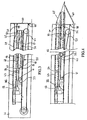
- the access ramp 5 (fig.1) is of a width substantially equal to that of the access door of the bus and greater than the width of a wheelchair for the disabled and especially for stroller for children.
- Cassette housing 3 is, of preferably closed by a flap 42 articulated along an edge lower 15 cassette housing 3 parallel to the threshold 1 of the access door and located in a plane perpendicular to floor 2 of the bus passing through the threshold 1 of the door access and retracts when the exit movement of the access ramp 5 (fig.2A) is in progress.
- the means of maneuver 12 (fig.1) of the ramp 5 consists of at least one toothed belt 16, or any another equivalent means, rotating in a loop, between a first driving wheel 17 and a second rotating wheel 18 crazy on its axis, comprising a motor strand 19 and a strand back 20 oriented parallel to a direction of translation 21 of the access ramp 5; the motor strand 19 is secured to a connection point 22 of a slide of maneuver 34 moving by translation, thanks to means guide 11 parallel to the direction of translation 21 of the access ramp 5 and connected to the rear end 8 of ramp by means of adjustment 10.
- the first driving wheel 17 is actuated, for example, by a geared motor assembly 26 operating, for example, thanks to an electric current continuous provided by the bus's electrical network; when the drive wheel 17 rotates in a first direction of rotation the toothed belt 16 brings out the ramp 5 and when the driving wheel 17 turns in a second direction the toothed belt 16 enters the access ramp 5; the meaning of rotation of the driving wheel 17 is defined by the direction of electric current flowing in the geared motor 26; the setting in motion of the geared motor 26 is controlled by example, by the bus driver and the control of the end of the movement of exit or re-entry of ramp being done, for example, by limit switches actuated by the movement of the operating slide 34; in one improvement of the invention, one can have a contact of end of ramp exit motion placed at the front end 7 and has the advantage of blocking or to reverse the movement of the ramp 5 when meets an obstacle.
- the ramp 5 relies, for example, on two rollers 71 very spaced apart (fig.6) or pads, while the guide means 11 (fig.1) of the operating slide 34 is constituted by example, two guide rails 27 parallel to the direction of translation 21 located on either side of the ramp 5, each having an upper guide 28 and a lower guide 29, parallel to each other, between which circulates one or more guide rollers 32, or any other equivalent device, the axes of which are disposed on either side of said slide 34; these guide rails 27 are of a substantially equal to the length of the ramp 5 increased by that of the maneuvering slide 34 and are internal to the housing cassette 3; as the movement out of the ramp 5 and when the rear 8 of the ramp 5 exceeds the rollers 71, its front end 7 comes into contact with the ground, while the middle 10 adjusts the rear 8 ramp to the level threshold 1 (Fig. 2C).
- the slides 27 can also be used to guide several pairs of rollers 30 whose axes are interdependent on both sides of the ramp 5; as the movement goes out of the access ramp 5, the rollers 30 escape in pairs of the front end 31 of the guide rails 27 and allow the front end 7 of the ramp 5 to lower gradually up to its support on the ground 70, while the rear end 8 of the ramp is raised thanks to the means of adjustment 10.
- a means 10, located between the maneuvering slide 34 (fig.1 and fig.2A) and the access ramp 5, is made by two links 35 constituting a linkage joint; the rods 35 are articulated on the one hand on the slide of maneuver 34 along a first axis of rotation 36 perpendicular to the translation direction 21 of the ramp access 5 and parallel to the threshold 1 of the access door and, on the other hand, on the rear end 8 of ramp following a second axis of rotation 37 parallel to the first axis of rotation 36; during the translation of the ramp 5 the first and second axes of rotation 36 and 37 are in a plane parallel to the rolling face 9 of the ramp access 5; these two links 35, located on both sides other of the ramp 5, each comprise a cam 38 and a stop 39, located on the upper part of the corresponding link; towards the end of the movement ramp exit, at the moment where the back 8 of the ramp 51 escapes the rollers 71 or that the last pair of rollers 30 leave the slides 27, the cams 38 come into contact
- the flap 42 is preferably articulated on the lower edge 15 of the ramp opening 4 and kept in position closing when the access ramp 5 is inside the casing cassette 3 thanks to several springs; during the movement, the shutter 42 retracts under the pressure of the ramp access 5 and gets up under the action of the springs at the end of reentry movement.
- a ramp extension 44 coming from extend the ramp 43 by its front end 45 of ramp, to reduce the angle of the slope and which lodges under the access ramp 43 forming a housing for the ramp extension 44 having a rear end 47 and which consists of a rigid panel having substantially the shape of that of the ramp 43 with a second face 48 at its upper part, substantially parallel to the first rolling face 49 and sliding directly under the ramp 43 so that the face 48 of the extension 44 is as close as possible the ramp 43;
- the length of the ramp extension 44 is substantially less than that of the ramp 43 so as to be able to lodge, in the zone of the end rear 52 ramp, the maneuvering means 53 of the ramp extension 44 while remaining entirely under the access ramp 43 in the retracted position;
- movement Relative output output is preferably limited to about three quarters of the length of the ramp extension 44, by an extension stop 54, which can be integral with the ramp or maneuvering means, so as to keep about a quarter of the length to do office rigid fitting so that the ramp extension
- the ramp extension 44 is, in the preferred version of the invention, controlled by the movement of the access ramp 43 thanks, on the one hand to a retainer 55 and. on the other hand, to a thrust device 56;
- the device retainer 55 is, for example, constituted by a strap of 57 or, alternatively, a cable having a first and second ends 58 and 59, the first of which end 58 is secured to the cassette housing 46 to near the flap 60, the retaining strap 57 passing then on a pulley 61 whose axis is fixed by report to ramp 43 and located in the vicinity of the rear end 52 of ramp, the retaining strap 57 being then secured by its second end 59 to the end back 47 extension;
- the pushing device 56 is consisting of, for example, a spring that is compressed, or by a pneumatic cylinder whose compartment, which allows take out the cylinder rod from the body, is under pressure permanent or any other equivalent device; the pushing device 56 takes support directly or indirectly, on the one hand on the access ramp 43, on the vicinity of the
- boom extension 44 When the return movement of ramp is engaged boom extension 44 remains in position output as the retaining means 57 is not stretched; from that the retaining means 57 is stretched during the movement of the return pulley, the return pulley 61 away from the first end 58, initiates the relative return movement of extension which continues until the end of the movement of back to the ramp.
- the guidance of the extension 44 can be achieved by pairs of rollers 51 guided in slides 50 integral with the side walls of the access ramp 43 forming housing.
- the rear end 63 extension (fig.5) has a retainer 64 in which a retaining hook 65, controlled by an electromechanical device 66, fixed with respect to the access ramp 67, is susceptible to commit; when the retaining hook 65 is engaged, the ramp extension 68 remains partially in its housing 69 located under the ramp 67; the order of Blocking the boom extension 68 may be at the level from the driving position of the bus.
Landscapes
- Health & Medical Sciences (AREA)
- Public Health (AREA)
- Engineering & Computer Science (AREA)
- Animal Behavior & Ethology (AREA)
- Life Sciences & Earth Sciences (AREA)
- Mechanical Engineering (AREA)
- General Health & Medical Sciences (AREA)
- Veterinary Medicine (AREA)
- Transportation (AREA)
- Vehicle Step Arrangements And Article Storage (AREA)
- Body Structure For Vehicles (AREA)
- Vehicle Waterproofing, Decoration, And Sanitation Devices (AREA)
- Steering Devices For Bicycles And Motorcycles (AREA)
- Fittings On The Vehicle Exterior For Carrying Loads, And Devices For Holding Or Mounting Articles (AREA)
- Lock And Its Accessories (AREA)
Claims (4)
- Durch eine steife Platte in deutlich rechteckiger Form gebildete Zugangsrampe (5, 43) zu einem Autobus ab der Höhe des Erdbodens (70) bis zum Fußboden (2) des Fahrzeugs mit Übergang über die Schwelle (1) einer Zugangstür, mit einem vorderen Ende (7, 45) und einem hinteren Ende (8, 52) und einer ersten Rollseite (9) an ihrem oberen Teil, wobei die genannte Rampe in einem unter dem Fußboden (2) des Autobusses platzierten Kassettengehäuse (3, 46) enthalten ist und eine sich gegenüber der Schwelle (1) befindende und durch eine das Ausfahren oder das Einfahren der Rampe, deren hinteres Ende (8, 52) mit dem Kassettengehäuse (3, 46) verbunden bleibt, erlaubende Klappe (42, 60) verschlossene Öffnung (4) umfasst, wobei das hinter Ende sich durch wenigstens einen Schwingarm (10, 35) an der Schwelle (1) der Zugangstür am Ende der Ausgangsbewegung der Rampe anpasst, die durch wenigstens einen sich in einer Schleife drehenden und durch Walzen (30), Kufen (32), Rollen (71) und Gleitschienen (27) geführten gezahnten Treibriemen (12, 16, 53) angetrieben wird, wobei die Ausgangsbewegung der Rampe durch ihr auf dem Erdboden (70) zum Aufliegen kommendes vorderes Ende (7, 45) erfolgt, dadurch gekennzeichnet, dass die Zugangsrampe (43) einer aus einer steifen Platte mit einer Rollseite (48) und einem hinteren Ende (47) gebildeten Verlängerung (44) zugeordnet ist, die unter der genannten Zugangsrampe (43), deren Verschiebung die Betätigung mittels eines Halteriemens (55, 57) und einer Schubfeder (56) steuert, um die genannte Verlängerung in die Verlängerung der vorderen Seite (45) der Rampe (43) zu verbringen, untergebracht ist und darunter gleitet.
- Zugangsrampe gemäß Anspruch 1, dadurch gekennzeichnet, dass der Halteriemen (57) der Verlängerung (44) ein mit dem Kassettengehäuse (46) fest befestigtes erstes Ende (58) in der Nähe der Klappe (60) und ein zweites, am hinteren Ende (47) der genannten Verlängerung (44) befestigtes Ende (59) mit einem Durchgang auf einer Umlenktrommel (61) umfasst, deren Achse im Verhältnis zur Zugangsrampe (43) befestigt ist, während die Schubvorrichtung (56) sich direkt einerseits auf der Zugangsrampe (43) in der Nähe ihres hinteren Endes (52) aufstützt und andererseits am hinteren Ende (47) der Verlängerung (44).
- Zugangsrampe gemäß Anspruch 1, dadurch gekennzeichnet, dass der ein Verbindungsgelenk einerseits auf einem Bedienschlitten (34) gemäß einer ersten Rotationsachse (36) und andererseits auf dem hinteren Ende (8, 52) der Rampe (43) gemäß einer zweiten Rotationsachse (37) bildende Schwingarm (35) eine Nocke (38) und einen Anschlag (39) umfasst, wobei die Nocke (38) in Kontakt mit einer Hebewalze (40) kommt, deren Rotationsachse an dem Kassettengehäuse (3, 46) befestigt und mit ihm fest verbunden ist und die bei Abschluss der Ausgangsbewegung der Rampe das Anheben der zweiten Rotationsachse (37) hervorruft, bis ein Schwenken des Schwingarms (35) um 90° erreicht wird, dessen Anschlag (39) sich auf einem fest mit dem Bedienschlitten (34) oder dem Kassettengehäuse (3, 4) verbunden Stopper (41) aufstützt.
- Zugangsrampe gemäß Anspruch 1, dadurch gekennzeichnet, dass eine Blockiervorrichtung auf Wunsch die Begrenzung des Ausfahrens der Rampenverlängerung erlaubt.
Applications Claiming Priority (3)
| Application Number | Priority Date | Filing Date | Title |
|---|---|---|---|
| FR0008697 | 2000-07-05 | ||
| FR0008697A FR2811223B1 (fr) | 2000-07-05 | 2000-07-05 | Rampe d'acces telescopique motorisee pour les vehicules de transport public |
| PCT/FR2001/002145 WO2002002043A1 (fr) | 2000-07-05 | 2001-07-05 | Rampe d'acces telescopique motorisee pour les vehicules de transport public |
Publications (2)
| Publication Number | Publication Date |
|---|---|
| EP1296628A1 EP1296628A1 (de) | 2003-04-02 |
| EP1296628B1 true EP1296628B1 (de) | 2005-06-15 |
Family
ID=8852103
Family Applications (1)
| Application Number | Title | Priority Date | Filing Date |
|---|---|---|---|
| EP01951773A Expired - Lifetime EP1296628B1 (de) | 2000-07-05 | 2001-07-05 | Motorisierte teleskoprampe für fahrzeuge des öffentlichen personenverkehrs |
Country Status (5)
| Country | Link |
|---|---|
| EP (1) | EP1296628B1 (de) |
| AT (1) | ATE297710T1 (de) |
| DE (1) | DE60111526D1 (de) |
| FR (1) | FR2811223B1 (de) |
| WO (1) | WO2002002043A1 (de) |
Cited By (1)
| Publication number | Priority date | Publication date | Assignee | Title |
|---|---|---|---|---|
| WO2019074825A1 (en) * | 2017-10-09 | 2019-04-18 | The Braun Corporation | RAMP ASSEMBLY FOR MOTOR VEHICLE |
Families Citing this family (7)
| Publication number | Priority date | Publication date | Assignee | Title |
|---|---|---|---|---|
| GB2405852A (en) * | 2003-09-13 | 2005-03-16 | Manganese Bronze Components Lt | Ramp assembly |
| EP1755920A4 (de) | 2004-05-10 | 2007-12-26 | Kevin John Fullerton | Überbrückungsvorrichtung |
| FR2887504B1 (fr) * | 2005-06-28 | 2008-08-08 | Metalic Sarl | Rampe escamotable d'acces a un vehicule, vehicule de transport public notamment |
| FR2908092B1 (fr) * | 2006-11-08 | 2009-02-13 | Solignat Sarl | Dispositif de chargement et/ou dechargement d'un vehicule de transport, module de plancher d'un vehicule de transport et vehicule de transport |
| FR2931406B1 (fr) | 2008-05-21 | 2010-11-19 | Metalic | Dispositif de securite pour un caisson de rampe d'acces de vehicule de transport public |
| FR2944955B1 (fr) * | 2009-04-29 | 2012-12-14 | Metalic | Rampe escamotable d'acces a un vehicule |
| AT519536B1 (de) * | 2016-12-20 | 2018-10-15 | Siemens Ag Oesterreich | Spaltüberbrückung |
Family Cites Families (6)
| Publication number | Priority date | Publication date | Assignee | Title |
|---|---|---|---|---|
| FR2587667B1 (fr) * | 1985-09-25 | 1989-10-20 | Alsthom | Dispositif permettant un acces aise aux vehicules ferroviaires lors des arrets en station |
| US4850788A (en) * | 1987-07-13 | 1989-07-25 | Dickson Industries, Inc. | Ramp assembly for trailers and the like |
| US5393192A (en) * | 1993-10-01 | 1995-02-28 | Reb Manufacturing Co., Inc. | Underfloor extendible ramp for vehicles |
| EP0931532A1 (de) * | 1998-01-28 | 1999-07-28 | IFE Industrie-Einrichtungen Fertigungs-Aktiengesellschaft | Rampe für Fahrzeuge |
| US6010298A (en) * | 1998-04-15 | 2000-01-04 | Lift-U Division Of Hogan Mfg., Inc. | Low floor vehicle ramp assembly |
| GB9821674D0 (en) * | 1998-10-05 | 1998-12-02 | Intellitec Mv Ltd | Ramp |
-
2000
- 2000-07-05 FR FR0008697A patent/FR2811223B1/fr not_active Expired - Lifetime
-
2001
- 2001-07-05 WO PCT/FR2001/002145 patent/WO2002002043A1/fr active IP Right Grant
- 2001-07-05 DE DE60111526T patent/DE60111526D1/de not_active Expired - Fee Related
- 2001-07-05 AT AT01951773T patent/ATE297710T1/de not_active IP Right Cessation
- 2001-07-05 EP EP01951773A patent/EP1296628B1/de not_active Expired - Lifetime
Cited By (2)
| Publication number | Priority date | Publication date | Assignee | Title |
|---|---|---|---|---|
| WO2019074825A1 (en) * | 2017-10-09 | 2019-04-18 | The Braun Corporation | RAMP ASSEMBLY FOR MOTOR VEHICLE |
| US10813802B2 (en) | 2017-10-09 | 2020-10-27 | The Braun Corporation | Ramp assembly for motorized vehicle |
Also Published As
| Publication number | Publication date |
|---|---|
| ATE297710T1 (de) | 2005-07-15 |
| FR2811223B1 (fr) | 2003-01-03 |
| WO2002002043A1 (fr) | 2002-01-10 |
| DE60111526D1 (de) | 2005-07-21 |
| EP1296628A1 (de) | 2003-04-02 |
| FR2811223A1 (fr) | 2002-01-11 |
Similar Documents
| Publication | Publication Date | Title |
|---|---|---|
| FR2495068A1 (fr) | Toit ouvrant pour vehicule | |
| FR2729898A1 (fr) | Perfectionnements aux glissieres pour sieges de vehicules et aux sieges equipes de telles glissieres | |
| FR2539081A1 (fr) | Toit coulissant-levant pour vehicule | |
| EP1296628B1 (de) | Motorisierte teleskoprampe für fahrzeuge des öffentlichen personenverkehrs | |
| EP2178484B1 (de) | Hebevorrichtung für einen rollstuhl | |
| FR2527145A1 (fr) | Ensemble de panneau de toit ouvrant pour vehicules automobiles | |
| EP0485797B1 (de) | Dreiteilige Staufalzvorrichtung | |
| EP3028924A1 (de) | Von einem fussgänger gezogener wagen zum passieren von stufen | |
| EP2694306B1 (de) | Glasdach mit verschiebbarer und schwenkbarer mobiler platte | |
| EP0884218B1 (de) | Bewegbare Trittstufe für ein Fahrzeug | |
| FR2703720A1 (fr) | Dispositif de verrouillage automatique d'une porte, en particulier d'une porte basculante. | |
| FR2512485A1 (fr) | Dispositif pour commander une porte basculante, et porte ainsi equipee | |
| EP1420980B1 (de) | Verfahren zur steuerung der seitengeländer eines fahrzeugaufzugs und vorrichtung dafür | |
| FR2845037A1 (fr) | Toit ouvrant pour vehicule automobile | |
| FR2716146A1 (fr) | Dispositif élévateur de fauteuil roulant repliable sur le toit d'un véhicule automobile. | |
| FR2817804A1 (fr) | Mecanisme de fermeture de toit ouvrant en toile pour vehicule automobile | |
| FR2818895A1 (fr) | Dispositif elevateur pour l'acces de personnes a mobilite reduite a de vehicules de transport en commun | |
| FR2587018A1 (fr) | Dispositif elevateur de fauteuil roulant sur vehicule automobile | |
| FR2502079A1 (fr) | Amenagement des vehicules en vue d'en faciliter l'acces et vehicules pourvus de cet amenagement | |
| EP0595717A1 (de) | Verriegel-und Entriegelungsvorrichtung für eine zweiflügelige Tür und eine Tür mit einer solchen Vorrichtung | |
| FR2591211A1 (fr) | Dispositif de chargement et de dechargement pour vehicule automobile | |
| FR2719528A1 (fr) | Dispositif de blocage latéral de chariots placés en file notamment dans des compartiments d'engins mobiles. | |
| WO1998024654A1 (fr) | Porte arriere de dechargement de benne basculante | |
| FR2935331A1 (fr) | Installation mecanique pour le transport d'une personne sur une bicyclette ou analogue | |
| FR2770813A1 (fr) | Dispositif escamotable de mise au repos d'un hayon elevateur a rails inclines fixes a l'arriere d'un vehicule |
Legal Events
| Date | Code | Title | Description |
|---|---|---|---|
| PUAI | Public reference made under article 153(3) epc to a published international application that has entered the european phase |
Free format text: ORIGINAL CODE: 0009012 |
|
| 17P | Request for examination filed |
Effective date: 20030122 |
|
| AK | Designated contracting states |
Kind code of ref document: A1 Designated state(s): AT BE CH CY DE DK ES FI FR GB GR IE IT LI LU MC NL PT SE TR |
|
| GRAP | Despatch of communication of intention to grant a patent |
Free format text: ORIGINAL CODE: EPIDOSNIGR1 |
|
| GRAS | Grant fee paid |
Free format text: ORIGINAL CODE: EPIDOSNIGR3 |
|
| GRAA | (expected) grant |
Free format text: ORIGINAL CODE: 0009210 |
|
| AK | Designated contracting states |
Kind code of ref document: B1 Designated state(s): AT BE CH CY DE DK ES FI FR GB GR IE IT LI LU MC NL PT SE TR |
|
| PG25 | Lapsed in a contracting state [announced via postgrant information from national office to epo] |
Ref country code: IT Free format text: LAPSE BECAUSE OF FAILURE TO SUBMIT A TRANSLATION OF THE DESCRIPTION OR TO PAY THE FEE WITHIN THE PRESCRIBED TIME-LIMIT;WARNING: LAPSES OF ITALIAN PATENTS WITH EFFECTIVE DATE BEFORE 2007 MAY HAVE OCCURRED AT ANY TIME BEFORE 2007. THE CORRECT EFFECTIVE DATE MAY BE DIFFERENT FROM THE ONE RECORDED. Effective date: 20050615 Ref country code: IE Free format text: LAPSE BECAUSE OF FAILURE TO SUBMIT A TRANSLATION OF THE DESCRIPTION OR TO PAY THE FEE WITHIN THE PRESCRIBED TIME-LIMIT Effective date: 20050615 Ref country code: FI Free format text: LAPSE BECAUSE OF FAILURE TO SUBMIT A TRANSLATION OF THE DESCRIPTION OR TO PAY THE FEE WITHIN THE PRESCRIBED TIME-LIMIT Effective date: 20050615 Ref country code: GB Free format text: LAPSE BECAUSE OF FAILURE TO SUBMIT A TRANSLATION OF THE DESCRIPTION OR TO PAY THE FEE WITHIN THE PRESCRIBED TIME-LIMIT Effective date: 20050615 Ref country code: TR Free format text: LAPSE BECAUSE OF FAILURE TO SUBMIT A TRANSLATION OF THE DESCRIPTION OR TO PAY THE FEE WITHIN THE PRESCRIBED TIME-LIMIT Effective date: 20050615 Ref country code: AT Free format text: LAPSE BECAUSE OF FAILURE TO SUBMIT A TRANSLATION OF THE DESCRIPTION OR TO PAY THE FEE WITHIN THE PRESCRIBED TIME-LIMIT Effective date: 20050615 Ref country code: NL Free format text: LAPSE BECAUSE OF FAILURE TO SUBMIT A TRANSLATION OF THE DESCRIPTION OR TO PAY THE FEE WITHIN THE PRESCRIBED TIME-LIMIT Effective date: 20050615 |
|
| REG | Reference to a national code |
Ref country code: CH Ref legal event code: EP Ref country code: GB Ref legal event code: FG4D Free format text: NOT ENGLISH |
|
| PG25 | Lapsed in a contracting state [announced via postgrant information from national office to epo] |
Ref country code: CY Free format text: LAPSE BECAUSE OF FAILURE TO SUBMIT A TRANSLATION OF THE DESCRIPTION OR TO PAY THE FEE WITHIN THE PRESCRIBED TIME-LIMIT Effective date: 20050705 Ref country code: LU Free format text: LAPSE BECAUSE OF NON-PAYMENT OF DUE FEES Effective date: 20050705 |
|
| REF | Corresponds to: |
Ref document number: 60111526 Country of ref document: DE Date of ref document: 20050721 Kind code of ref document: P |
|
| REG | Reference to a national code |
Ref country code: IE Ref legal event code: FG4D Free format text: LANGUAGE OF EP DOCUMENT: FRENCH |
|
| PG25 | Lapsed in a contracting state [announced via postgrant information from national office to epo] |
Ref country code: BE Free format text: LAPSE BECAUSE OF NON-PAYMENT OF DUE FEES Effective date: 20050731 Ref country code: CH Free format text: LAPSE BECAUSE OF NON-PAYMENT OF DUE FEES Effective date: 20050731 Ref country code: MC Free format text: LAPSE BECAUSE OF NON-PAYMENT OF DUE FEES Effective date: 20050731 Ref country code: LI Free format text: LAPSE BECAUSE OF NON-PAYMENT OF DUE FEES Effective date: 20050731 |
|
| PG25 | Lapsed in a contracting state [announced via postgrant information from national office to epo] |
Ref country code: GR Free format text: LAPSE BECAUSE OF FAILURE TO SUBMIT A TRANSLATION OF THE DESCRIPTION OR TO PAY THE FEE WITHIN THE PRESCRIBED TIME-LIMIT Effective date: 20050915 Ref country code: DK Free format text: LAPSE BECAUSE OF FAILURE TO SUBMIT A TRANSLATION OF THE DESCRIPTION OR TO PAY THE FEE WITHIN THE PRESCRIBED TIME-LIMIT Effective date: 20050915 Ref country code: SE Free format text: LAPSE BECAUSE OF FAILURE TO SUBMIT A TRANSLATION OF THE DESCRIPTION OR TO PAY THE FEE WITHIN THE PRESCRIBED TIME-LIMIT Effective date: 20050915 |
|
| PG25 | Lapsed in a contracting state [announced via postgrant information from national office to epo] |
Ref country code: ES Free format text: LAPSE BECAUSE OF FAILURE TO SUBMIT A TRANSLATION OF THE DESCRIPTION OR TO PAY THE FEE WITHIN THE PRESCRIBED TIME-LIMIT Effective date: 20050926 |
|
| PG25 | Lapsed in a contracting state [announced via postgrant information from national office to epo] |
Ref country code: PT Free format text: LAPSE BECAUSE OF FAILURE TO SUBMIT A TRANSLATION OF THE DESCRIPTION OR TO PAY THE FEE WITHIN THE PRESCRIBED TIME-LIMIT Effective date: 20051124 |
|
| NLV1 | Nl: lapsed or annulled due to failure to fulfill the requirements of art. 29p and 29m of the patents act | ||
| GBV | Gb: ep patent (uk) treated as always having been void in accordance with gb section 77(7)/1977 [no translation filed] |
Effective date: 20050615 |
|
| REG | Reference to a national code |
Ref country code: IE Ref legal event code: FD4D |
|
| PG25 | Lapsed in a contracting state [announced via postgrant information from national office to epo] |
Ref country code: DE Free format text: LAPSE BECAUSE OF NON-PAYMENT OF DUE FEES Effective date: 20060201 |
|
| REG | Reference to a national code |
Ref country code: CH Ref legal event code: PL |
|
| PLBE | No opposition filed within time limit |
Free format text: ORIGINAL CODE: 0009261 |
|
| STAA | Information on the status of an ep patent application or granted ep patent |
Free format text: STATUS: NO OPPOSITION FILED WITHIN TIME LIMIT |
|
| PG25 | Lapsed in a contracting state [announced via postgrant information from national office to epo] |
Ref country code: FR Free format text: LAPSE BECAUSE OF NON-PAYMENT OF DUE FEES Effective date: 20060531 |
|
| 26N | No opposition filed |
Effective date: 20060316 |
|
| REG | Reference to a national code |
Ref country code: FR Ref legal event code: ST Effective date: 20060531 |
|
| BERE | Be: lapsed |
Owner name: METALIC SA Effective date: 20050731 |
|
| PG25 | Lapsed in a contracting state [announced via postgrant information from national office to epo] |
Ref country code: FR Free format text: LAPSE BECAUSE OF NON-PAYMENT OF DUE FEES Effective date: 20050731 |