EP1296431A2 - Ensemble de barres de distribution - Google Patents
Ensemble de barres de distribution Download PDFInfo
- Publication number
- EP1296431A2 EP1296431A2 EP02020192A EP02020192A EP1296431A2 EP 1296431 A2 EP1296431 A2 EP 1296431A2 EP 02020192 A EP02020192 A EP 02020192A EP 02020192 A EP02020192 A EP 02020192A EP 1296431 A2 EP1296431 A2 EP 1296431A2
- Authority
- EP
- European Patent Office
- Prior art keywords
- installation
- busbars
- tongues
- devices
- distribution according
- Prior art date
- Legal status (The legal status is an assumption and is not a legal conclusion. Google has not performed a legal analysis and makes no representation as to the accuracy of the status listed.)
- Withdrawn
Links
Images


Classifications
-
- H—ELECTRICITY
- H02—GENERATION; CONVERSION OR DISTRIBUTION OF ELECTRIC POWER
- H02G—INSTALLATION OF ELECTRIC CABLES OR LINES, OR OF COMBINED OPTICAL AND ELECTRIC CABLES OR LINES
- H02G5/00—Installations of bus-bars
- H02G5/005—Laminated bus-bars
-
- H—ELECTRICITY
- H05—ELECTRIC TECHNIQUES NOT OTHERWISE PROVIDED FOR
- H05K—PRINTED CIRCUITS; CASINGS OR CONSTRUCTIONAL DETAILS OF ELECTRIC APPARATUS; MANUFACTURE OF ASSEMBLAGES OF ELECTRICAL COMPONENTS
- H05K3/00—Apparatus or processes for manufacturing printed circuits
- H05K3/10—Apparatus or processes for manufacturing printed circuits in which conductive material is applied to the insulating support in such a manner as to form the desired conductive pattern
- H05K3/20—Apparatus or processes for manufacturing printed circuits in which conductive material is applied to the insulating support in such a manner as to form the desired conductive pattern by affixing prefabricated conductor pattern
- H05K3/202—Apparatus or processes for manufacturing printed circuits in which conductive material is applied to the insulating support in such a manner as to form the desired conductive pattern by affixing prefabricated conductor pattern using self-supporting metal foil pattern
-
- H—ELECTRICITY
- H05—ELECTRIC TECHNIQUES NOT OTHERWISE PROVIDED FOR
- H05K—PRINTED CIRCUITS; CASINGS OR CONSTRUCTIONAL DETAILS OF ELECTRIC APPARATUS; MANUFACTURE OF ASSEMBLAGES OF ELECTRICAL COMPONENTS
- H05K1/00—Printed circuits
- H05K1/02—Details
- H05K1/0296—Conductive pattern lay-out details not covered by sub groups H05K1/02 - H05K1/0295
- H05K1/0298—Multilayer circuits
-
- H—ELECTRICITY
- H05—ELECTRIC TECHNIQUES NOT OTHERWISE PROVIDED FOR
- H05K—PRINTED CIRCUITS; CASINGS OR CONSTRUCTIONAL DETAILS OF ELECTRIC APPARATUS; MANUFACTURE OF ASSEMBLAGES OF ELECTRICAL COMPONENTS
- H05K2201/00—Indexing scheme relating to printed circuits covered by H05K1/00
- H05K2201/09—Shape and layout
- H05K2201/09009—Substrate related
- H05K2201/09118—Moulded substrate
-
- H—ELECTRICITY
- H05—ELECTRIC TECHNIQUES NOT OTHERWISE PROVIDED FOR
- H05K—PRINTED CIRCUITS; CASINGS OR CONSTRUCTIONAL DETAILS OF ELECTRIC APPARATUS; MANUFACTURE OF ASSEMBLAGES OF ELECTRICAL COMPONENTS
- H05K2201/00—Indexing scheme relating to printed circuits covered by H05K1/00
- H05K2201/10—Details of components or other objects attached to or integrated in a printed circuit board
- H05K2201/10431—Details of mounted components
- H05K2201/1059—Connections made by press-fit insertion
-
- H—ELECTRICITY
- H05—ELECTRIC TECHNIQUES NOT OTHERWISE PROVIDED FOR
- H05K—PRINTED CIRCUITS; CASINGS OR CONSTRUCTIONAL DETAILS OF ELECTRIC APPARATUS; MANUFACTURE OF ASSEMBLAGES OF ELECTRICAL COMPONENTS
- H05K3/00—Apparatus or processes for manufacturing printed circuits
- H05K3/30—Assembling printed circuits with electric components, e.g. with resistor
- H05K3/306—Lead-in-hole components, e.g. affixing or retention before soldering, spacing means
- H05K3/308—Adaptations of leads
Definitions
- the invention relates to an electrical installation distribution according to the preamble of claim 1.
- Such distribution boards are used in buildings for power distribution and protection Installed ; in an installation distributor housing there are miniature circuit breakers, Residual current circuit breakers and the like. With which individual consumers within of a network are to be protected.
- Such housings usually contain top-hat rail on their housing base, on which the switchgear is snapped on.
- busbars the switching devices are connected to one another in phases, with single-phase devices only one busbar and so-called for multi-phase arrangements
- Busbar blocks are used that have a busbar receptacle with several chambers and have ribbon conductors inserted into the chambers, whereby connection tabs are provided on the ribbon conductors, which are in terminals can be plugged into the switchgear and clamped into it. If several hat profile support rails are arranged one above the other, then there are connecting conductor arrangements provided with which the individual busbars are connected become.
- An access line with the busbars is introduced into the distribution is connected; are the outgoing lines assigned to the individual switching devices laid within the distribution box and led out of the housing, the outgoing lines connected to the supply lines to the consumers become.
- incorrect connections can result from mistakes, For example, such that one to be protected by means of a residual current circuit breaker Consumer mistakenly connected to a circuit breaker becomes.
- the object of the invention is an installation distribution of the type mentioned to create, in which the assembly is simplified even further and incorrect connections be avoided.
- the busbars of different phases are in the same plane arranged in phases isolated from each other, and are in an insulating body embedded, preferably cast in.
- Each conductor rail can have one for each phase, transverse to the direction in which the devices are connected have extending connecting section, at which one of the number of installation devices - Rows of appropriate number of tongues are attached below of the devices and the opening for plug-in elements on the installation devices exhibit.
- the conductor rail for the neutral conductor also points a connecting section running transversely to the direction of the installation devices on the number corresponding to the number of installation device rows are attached by tongues that run below the installation devices and which have the receiving openings for the plug elements.
- the busbars can be arranged one above the other, the tongues different phases are offset from each other.
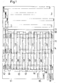
- Fig. 1 shows a plan view of a busbar arrangement, which is in a busbar housing can be used, as shown in FIGS. 2 and 3.
- the busbar L1 has a perpendicular to the direction of the installation devices extending connecting piece 61, on which tongues 62, 63 and 64 are formed perpendicularly thereto are.
- the length of the connecting piece 61 corresponds to the distance between the installation device rows from each other and the length of the tongues 62 to 64 corresponds to that Length of the installed switchgear in the row direction.
- the busbar L2 is constructed in a similar manner. It has a connecting bridge 65, on which a number of tongues corresponding to the number of phases 66.67 and 68 is molded.
- the tongues 66 and 62 67 and 63, 68 and 64 run parallel towards each other and project from their connecting bridges in the same direction.
- a third phase conductor L3, which is a connecting part, is assigned to these two phase conductors 69 has, on which tongues 70, 71 and 72 are formed.
- the connecting part 69 is located near the ends of the tongues 62,66; 63.67; 64.68 and tongues 70, 71 and 72 jump in the opposite direction to the connectors 61 and 65 before.
- a neutral conductor N Associated with the three phase conductors is a neutral conductor N, which has a similar structure has, with a connector 73 below the connector of the 69th and with the tongues projecting in the same direction as the tongues 70, 71 and 72 74,75,76,77,78,79,80,81. Furthermore, a plate is provided as PE conductor, which is below of the individual phase rails and the neutral conductor.
- FIG. 3 shows a cross section through the busbars embedded in insulating material. It can be seen that the individual busbars in different levels are arranged.
- the busbar L1 is located with its tongue 64 in the first level, d. H. on the top level.
- this busbar or tongue 64 has openings 80 through those shown in more detail below Grip contact springs 81 through.
- a beaks contact spring 81 just opens 80; that of Fig. 3b engages the contact spring 81 into a blind hole 82 located below the tongue 64.
- the tongue 68 is located in the plane below the tongue 64; through a through opening 83 a contact spring element 81 comes into contact with the tongue 68, the tongue 68 through an opening 84 in the tongue 68 which in one below located blind hole 85 engages. Contacting of the tongue 64 is avoided by that the through opening 83 is dimensioned sufficiently large.
- a tongue 70 could, for example, be provided in the level further below be, through the opening 86 through which the contact spring 81 is inserted; in Fig. 3e, the contact spring 81 with a busbar in the 4th level, i. H. contacted with the tongue of the neutral conductor 75, for example.
- Fig. 3 (3a to 3e) shows that the individual busbars in the insulating body 90 are embedded, access to openings 90,92,93 / 84,94 and 95 to the individual Has tongues.
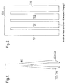
- FIG. 2 shows the arrangement according to FIG. 3 in a schematic representation, where no four levels, but only three levels of busbars one above the other are shown lying.
- FIG. 2 also shows a contact element 96, which in the plane 1 and in the Level 3 busbars connected to each other. The reason why this is necessary, can be seen from Fig. 6.
- the one that receives the busbars Insulating material housing 100 which corresponds to the insulating material housing 90 of FIG. 8, has Openings 101, 102, 103, 104, 105 and 106 and openings 107, 108 and 109.
- FIG. 6 shows a section corresponding to FIG. 3 through a busbar housing ; there are a total of four busbar levels 110, 111, 112 and 113 intended.
- the busbar 110 located in the area of the opening 101 has an opening 114 which is smaller than the diameter of the hole 101.
- the busbar 111 has an opening 115 which is the same size than the opening 114, thus smaller than the hole 102.
- the busbar 112 has an opening 116, the inside diameter corresponds to the inner diameter 114 and 115. If a module with contact springs 3, inserted into openings 101, 102, 103, for example then these contact springs contact the busbar on the one hand 110, in addition the busbar 111 and the busbar 112.
- the busbar is located below these three busbars 110, 111 and 112 114; one recognizes that this busbar 113 openings 116, 117 and 118 owns; these openings 116 to 118 have the same diameter as that Opening 114, 115 and 116 and lie one above the other so that the phase of the busbar 110 by means of a contact piece, for example the contact piece 96 the busbar 113 can be placed.
- opening 107 inserted the contact piece, which the busbars 110 and 113 together combines.
- busbar 111 with the busbar 113 or the Busbar 112 can be contacted with the busbar 113.
- Fig. 6 a to the right of holes 101 to 106 are in a line therewith Holes 120, 121, 122, 123, 124 and 125 are provided; via busbar 113 can then be inserted into the holes 120 to 125 installation devices as needed be placed on the phase that is in the busbar 110, in the busbar 111 or in the busbar 112 is given.
- 11 shows a corresponding one Connection line 126 in dashed lines.
- FIG. 4 and 5 show a contact spring 81.
- a common contact carrier 130 On a common contact carrier 130 are prong-shaped tongues 131, 132, 133 and 134 which are formed against each other are bent, as can be seen from FIG. 9. There are to the right (see Fig. 4) bent tongues 131 and 133 and to the left bent tongues 132 and 134th
- Figures 7 to 10 show an embodiment of an installation device.
- the device is approximately T - or socket-shaped with a front side 140 and an attachment side 141 educated.
- 10 has two rotatably mounted double arm levers 150 and 151, with the lever arms 152 and 153 facing the fastening side are attacking springs 154 and 155 that separate the arms 152, 153 - and the others Press arms 156 and 157 against each other.
- the free ends of arms 156 and 157 have noses 158 and 159 to be facing one another; when assembling the Noses 158 and 159 behind the strips 148 and 149, the module with the bottom side 141 inserted in the direction of arrow 160 between the two double arm levers 51 and 151 becomes.
Landscapes
- Engineering & Computer Science (AREA)
- Manufacturing & Machinery (AREA)
- Microelectronics & Electronic Packaging (AREA)
- Installation Of Bus-Bars (AREA)
- Distribution Board (AREA)
Applications Claiming Priority (2)
| Application Number | Priority Date | Filing Date | Title |
|---|---|---|---|
| DE10146503 | 2001-09-21 | ||
| DE10146503A DE10146503A1 (de) | 2001-09-21 | 2001-09-21 | Elektrische Installationsverteilung |
Publications (2)
| Publication Number | Publication Date |
|---|---|
| EP1296431A2 true EP1296431A2 (fr) | 2003-03-26 |
| EP1296431A3 EP1296431A3 (fr) | 2004-10-27 |
Family
ID=7699756
Family Applications (1)
| Application Number | Title | Priority Date | Filing Date |
|---|---|---|---|
| EP02020192A Withdrawn EP1296431A3 (fr) | 2001-09-21 | 2002-09-10 | Ensemble de barres de distribution |
Country Status (3)
| Country | Link |
|---|---|
| US (1) | US20030067756A1 (fr) |
| EP (1) | EP1296431A3 (fr) |
| DE (1) | DE10146503A1 (fr) |
Cited By (1)
| Publication number | Priority date | Publication date | Assignee | Title |
|---|---|---|---|---|
| WO2022258191A1 (fr) | 2021-06-11 | 2022-12-15 | Duplico D.O.O. | Kit utilisé pour l'assemblage ou le démontage automatisé de circuits électriques stratifiés |
Families Citing this family (6)
| Publication number | Priority date | Publication date | Assignee | Title |
|---|---|---|---|---|
| DE102005015945B4 (de) * | 2005-04-07 | 2015-07-02 | Abb Ag | Kontakteinrichtung für eine zwei- oder mehrphasige Stromschienenanordnung |
| DE102006060569A1 (de) * | 2006-12-19 | 2008-07-10 | Friedrich Göhringer Elektrotechnik GmbH | Kontaktfahne für eine Sammelschiene |
| DE102008037966A1 (de) * | 2008-08-13 | 2010-02-18 | Siemens Aktiengesellschaft | Verfahren zur Herstellung einer mehrpoligen Anschluss- oder Abgangsstelle für eine Stromschiene mit koaxial angeordneten, rohrförmigen Teilleitern |
| DE102010050654B4 (de) * | 2010-11-09 | 2017-03-16 | Abb Ag | Anordnung von Leitern zum Anschluss eines Leistungsschalters |
| DE102012016133B4 (de) * | 2012-08-15 | 2014-09-11 | Diethelm Bienhaus | Elektrische Installationsverteilung mit Verbindungselementen sowie Verfahren zur Identifikation und Zuordnung von Installationsgeräten und Verbindungselementen |
| WO2019201419A1 (fr) * | 2018-04-16 | 2019-10-24 | Abb Schweiz Ag | Appareil d'interconnexion électrique de deux barres omnibus polyphasées stratifiées et armoire de distribution comprenant un tel appareil |
Citations (3)
| Publication number | Priority date | Publication date | Assignee | Title |
|---|---|---|---|---|
| EP0345851A1 (fr) * | 1988-06-07 | 1989-12-13 | Holec Systemen En Componenten B.V. | Armoire pour installation électrique |
| EP0639877A1 (fr) * | 1993-08-18 | 1995-02-22 | ABBPATENT GmbH | Dispositif pour alimenter en énergie électrique au moins un appareil d'installation électrique |
| US6002580A (en) * | 1996-12-09 | 1999-12-14 | Power Distribution Products International | Circuit breaker power distribution panel |
Family Cites Families (11)
| Publication number | Priority date | Publication date | Assignee | Title |
|---|---|---|---|---|
| US1736028A (en) * | 1922-10-21 | 1929-11-19 | Metropolitan Electric Mfg Comp | Electric panel or distribution board |
| DE1590329B1 (de) * | 1966-01-21 | 1972-05-04 | Ellison George Ltd | Elektrische Verteilereinrichtung |
| DE8813533U1 (fr) * | 1988-10-28 | 1988-12-15 | Asea Brown Boveri Ag, 6800 Mannheim, De | |
| US5139426A (en) * | 1991-12-11 | 1992-08-18 | Amp Incorporated | Adjunct power connector |
| DE4438805C1 (de) * | 1994-10-31 | 1996-03-07 | Weidmueller Interface | Feldbusanschlußmodul |
| DE19628957A1 (de) * | 1996-07-18 | 1998-01-22 | Abb Patent Gmbh | Anschlußvorrichtung für elektrische Installationsgeräte |
| DE29804284U1 (de) * | 1998-03-11 | 1998-05-07 | Weidmueller Interface | Steuerungsanlage für elektronische Steuerungs- und Automatisierungssysteme |
| DE19859717A1 (de) * | 1998-12-23 | 2000-06-29 | Moeller Gmbh | Schnell-Montage-Verdrahtungssystem |
| DE19964157A1 (de) * | 1999-01-25 | 2000-10-05 | Weidmueller Interface | Elektrisches Gerät |
| US6315580B1 (en) * | 1999-06-04 | 2001-11-13 | Astec International Limited | PCB connector module for plug-in circuit breakers and fuses |
| US6560123B1 (en) * | 1999-06-04 | 2003-05-06 | Astec International Limited | Plug-in GMT fuse block |
-
2001
- 2001-09-21 DE DE10146503A patent/DE10146503A1/de not_active Ceased
-
2002
- 2002-09-10 EP EP02020192A patent/EP1296431A3/fr not_active Withdrawn
- 2002-09-23 US US10/252,289 patent/US20030067756A1/en not_active Abandoned
Patent Citations (3)
| Publication number | Priority date | Publication date | Assignee | Title |
|---|---|---|---|---|
| EP0345851A1 (fr) * | 1988-06-07 | 1989-12-13 | Holec Systemen En Componenten B.V. | Armoire pour installation électrique |
| EP0639877A1 (fr) * | 1993-08-18 | 1995-02-22 | ABBPATENT GmbH | Dispositif pour alimenter en énergie électrique au moins un appareil d'installation électrique |
| US6002580A (en) * | 1996-12-09 | 1999-12-14 | Power Distribution Products International | Circuit breaker power distribution panel |
Cited By (1)
| Publication number | Priority date | Publication date | Assignee | Title |
|---|---|---|---|---|
| WO2022258191A1 (fr) | 2021-06-11 | 2022-12-15 | Duplico D.O.O. | Kit utilisé pour l'assemblage ou le démontage automatisé de circuits électriques stratifiés |
Also Published As
| Publication number | Publication date |
|---|---|
| US20030067756A1 (en) | 2003-04-10 |
| EP1296431A3 (fr) | 2004-10-27 |
| DE10146503A1 (de) | 2003-04-10 |
Similar Documents
| Publication | Publication Date | Title |
|---|---|---|
| EP2255410B1 (fr) | Barrette a bornes ou bloc de barrettes a bornes | |
| DE102010032383B4 (de) | Stromschienenverbinder und Stromschienensystem mit mindestens zwei benachbarten Stromschienen und einem Stromschienenverbinder | |
| EP1749336B1 (fr) | Distributeur de courant modulaire destine a des courants eleves | |
| DE19964157A1 (de) | Elektrisches Gerät | |
| EP3111515B1 (fr) | Barrette à bornes et bloc de barrettes à bornes | |
| DE102008017245A1 (de) | Steckadapter für ein elektrisches Schaltgerät | |
| EP0639877B1 (fr) | Dispositif pour alimenter en énergie électrique au moins un appareil d'installation électrique | |
| DE19902745A1 (de) | Elektrisches Gerät | |
| DE102019126155A1 (de) | Stromschienenmodul und entsprechendes Anschlussmodul | |
| EP0821454B1 (fr) | Dispositif de raccordement pour installation électrique | |
| EP0053252B1 (fr) | Adaptateur pour dispositifs d'installations électriques | |
| EP0454016A2 (fr) | Borne de réseau attachée sur un rail de support standardisÀ© | |
| EP1296431A2 (fr) | Ensemble de barres de distribution | |
| DE3817440A1 (de) | Stromschiene | |
| EP0252512B1 (fr) | Unité de connexion multiple | |
| DE102005023452B4 (de) | Montage- und Verdrahtungssystem für elektrische Funktionsmodule, insbesondere für Schaltgeräte | |
| EP1472766B1 (fr) | Dispositif de raccordement ou de distribution pour appareils electriques d'installation | |
| EP1787358B1 (fr) | Module d'alimentation electrique comportant des bornes a ressort de rappel de cage | |
| EP0762583A2 (fr) | Système de barres omnibus à basse tension | |
| EP0080646B1 (fr) | Socle pour un relais miniature | |
| DE102005047045B3 (de) | Anschlussadapter | |
| EP1353350B1 (fr) | Interrupteur auxiliaire | |
| DE10340212B4 (de) | Verteileranordnung | |
| EP0262554A2 (fr) | Dispositif de connexion d'appareils d'installation aux barres de courant d'un système de base de barres omnibus | |
| DE102016122437B4 (de) | Kontaktierungsvorrichtung |
Legal Events
| Date | Code | Title | Description |
|---|---|---|---|
| PUAI | Public reference made under article 153(3) epc to a published international application that has entered the european phase |
Free format text: ORIGINAL CODE: 0009012 |
|
| AK | Designated contracting states |
Kind code of ref document: A2 Designated state(s): AT BE BG CH CY CZ DE DK EE ES FI FR GB GR IE IT LI LU MC NL PT SE SK TR Designated state(s): AT BE BG CH CY CZ DE DK EE ES FI FR GB GR IE IT LI LU MC NL PT SE SK TR |
|
| AX | Request for extension of the european patent |
Extension state: AL LT LV MK RO SI |
|
| PUAL | Search report despatched |
Free format text: ORIGINAL CODE: 0009013 |
|
| AK | Designated contracting states |
Kind code of ref document: A3 Designated state(s): AT BE BG CH CY CZ DE DK EE ES FI FR GB GR IE IT LI LU MC NL PT SE SK TR |
|
| AX | Request for extension of the european patent |
Extension state: AL LT LV MK RO SI |
|
| 17P | Request for examination filed |
Effective date: 20041001 |
|
| AKX | Designation fees paid |
Designated state(s): DE FR GB IT |
|
| STAA | Information on the status of an ep patent application or granted ep patent |
Free format text: STATUS: THE APPLICATION IS DEEMED TO BE WITHDRAWN |
|
| 18D | Application deemed to be withdrawn |
Effective date: 20120403 |