EP1296431A2 - Bus bar assembly - Google Patents
Bus bar assembly Download PDFInfo
- Publication number
- EP1296431A2 EP1296431A2 EP02020192A EP02020192A EP1296431A2 EP 1296431 A2 EP1296431 A2 EP 1296431A2 EP 02020192 A EP02020192 A EP 02020192A EP 02020192 A EP02020192 A EP 02020192A EP 1296431 A2 EP1296431 A2 EP 1296431A2
- Authority
- EP
- European Patent Office
- Prior art keywords
- installation
- busbars
- devices
- tongues
- plug
- Prior art date
- Legal status (The legal status is an assumption and is not a legal conclusion. Google has not performed a legal analysis and makes no representation as to the accuracy of the status listed.)
- Withdrawn
Links
Images


Classifications
-
- H—ELECTRICITY
- H02—GENERATION; CONVERSION OR DISTRIBUTION OF ELECTRIC POWER
- H02G—INSTALLATION OF ELECTRIC CABLES OR LINES, OR OF COMBINED OPTICAL AND ELECTRIC CABLES OR LINES
- H02G5/00—Installations of bus-bars
- H02G5/005—Laminated bus-bars
-
- H—ELECTRICITY
- H05—ELECTRIC TECHNIQUES NOT OTHERWISE PROVIDED FOR
- H05K—PRINTED CIRCUITS; CASINGS OR CONSTRUCTIONAL DETAILS OF ELECTRIC APPARATUS; MANUFACTURE OF ASSEMBLAGES OF ELECTRICAL COMPONENTS
- H05K3/00—Apparatus or processes for manufacturing printed circuits
- H05K3/10—Apparatus or processes for manufacturing printed circuits in which conductive material is applied to the insulating support in such a manner as to form the desired conductive pattern
- H05K3/20—Apparatus or processes for manufacturing printed circuits in which conductive material is applied to the insulating support in such a manner as to form the desired conductive pattern by affixing prefabricated conductor pattern
- H05K3/202—Apparatus or processes for manufacturing printed circuits in which conductive material is applied to the insulating support in such a manner as to form the desired conductive pattern by affixing prefabricated conductor pattern using self-supporting metal foil pattern
-
- H—ELECTRICITY
- H05—ELECTRIC TECHNIQUES NOT OTHERWISE PROVIDED FOR
- H05K—PRINTED CIRCUITS; CASINGS OR CONSTRUCTIONAL DETAILS OF ELECTRIC APPARATUS; MANUFACTURE OF ASSEMBLAGES OF ELECTRICAL COMPONENTS
- H05K1/00—Printed circuits
- H05K1/02—Details
- H05K1/0296—Conductive pattern lay-out details not covered by sub groups H05K1/02 - H05K1/0295
- H05K1/0298—Multilayer circuits
-
- H—ELECTRICITY
- H05—ELECTRIC TECHNIQUES NOT OTHERWISE PROVIDED FOR
- H05K—PRINTED CIRCUITS; CASINGS OR CONSTRUCTIONAL DETAILS OF ELECTRIC APPARATUS; MANUFACTURE OF ASSEMBLAGES OF ELECTRICAL COMPONENTS
- H05K2201/00—Indexing scheme relating to printed circuits covered by H05K1/00
- H05K2201/09—Shape and layout
- H05K2201/09009—Substrate related
- H05K2201/09118—Moulded substrate
-
- H—ELECTRICITY
- H05—ELECTRIC TECHNIQUES NOT OTHERWISE PROVIDED FOR
- H05K—PRINTED CIRCUITS; CASINGS OR CONSTRUCTIONAL DETAILS OF ELECTRIC APPARATUS; MANUFACTURE OF ASSEMBLAGES OF ELECTRICAL COMPONENTS
- H05K2201/00—Indexing scheme relating to printed circuits covered by H05K1/00
- H05K2201/10—Details of components or other objects attached to or integrated in a printed circuit board
- H05K2201/10431—Details of mounted components
- H05K2201/1059—Connections made by press-fit insertion
-
- H—ELECTRICITY
- H05—ELECTRIC TECHNIQUES NOT OTHERWISE PROVIDED FOR
- H05K—PRINTED CIRCUITS; CASINGS OR CONSTRUCTIONAL DETAILS OF ELECTRIC APPARATUS; MANUFACTURE OF ASSEMBLAGES OF ELECTRICAL COMPONENTS
- H05K3/00—Apparatus or processes for manufacturing printed circuits
- H05K3/30—Assembling printed circuits with electric components, e.g. with resistors
- H05K3/306—Assembling printed circuits with electric components, e.g. with resistors with lead-in-hole components
- H05K3/308—Adaptations of leads
Definitions
- the invention relates to an electrical installation distribution according to the preamble of claim 1.
- Such distribution boards are used in buildings for power distribution and protection Installed ; in an installation distributor housing there are miniature circuit breakers, Residual current circuit breakers and the like. With which individual consumers within of a network are to be protected.
- Such housings usually contain top-hat rail on their housing base, on which the switchgear is snapped on.
- busbars the switching devices are connected to one another in phases, with single-phase devices only one busbar and so-called for multi-phase arrangements
- Busbar blocks are used that have a busbar receptacle with several chambers and have ribbon conductors inserted into the chambers, whereby connection tabs are provided on the ribbon conductors, which are in terminals can be plugged into the switchgear and clamped into it. If several hat profile support rails are arranged one above the other, then there are connecting conductor arrangements provided with which the individual busbars are connected become.
- An access line with the busbars is introduced into the distribution is connected; are the outgoing lines assigned to the individual switching devices laid within the distribution box and led out of the housing, the outgoing lines connected to the supply lines to the consumers become.
- incorrect connections can result from mistakes, For example, such that one to be protected by means of a residual current circuit breaker Consumer mistakenly connected to a circuit breaker becomes.
- the object of the invention is an installation distribution of the type mentioned to create, in which the assembly is simplified even further and incorrect connections be avoided.
- the busbars of different phases are in the same plane arranged in phases isolated from each other, and are in an insulating body embedded, preferably cast in.
- Each conductor rail can have one for each phase, transverse to the direction in which the devices are connected have extending connecting section, at which one of the number of installation devices - Rows of appropriate number of tongues are attached below of the devices and the opening for plug-in elements on the installation devices exhibit.
- the conductor rail for the neutral conductor also points a connecting section running transversely to the direction of the installation devices on the number corresponding to the number of installation device rows are attached by tongues that run below the installation devices and which have the receiving openings for the plug elements.
- the busbars can be arranged one above the other, the tongues different phases are offset from each other.
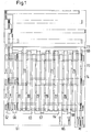
- Fig. 1 shows a plan view of a busbar arrangement, which is in a busbar housing can be used, as shown in FIGS. 2 and 3.
- the busbar L1 has a perpendicular to the direction of the installation devices extending connecting piece 61, on which tongues 62, 63 and 64 are formed perpendicularly thereto are.
- the length of the connecting piece 61 corresponds to the distance between the installation device rows from each other and the length of the tongues 62 to 64 corresponds to that Length of the installed switchgear in the row direction.
- the busbar L2 is constructed in a similar manner. It has a connecting bridge 65, on which a number of tongues corresponding to the number of phases 66.67 and 68 is molded.
- the tongues 66 and 62 67 and 63, 68 and 64 run parallel towards each other and project from their connecting bridges in the same direction.
- a third phase conductor L3, which is a connecting part, is assigned to these two phase conductors 69 has, on which tongues 70, 71 and 72 are formed.
- the connecting part 69 is located near the ends of the tongues 62,66; 63.67; 64.68 and tongues 70, 71 and 72 jump in the opposite direction to the connectors 61 and 65 before.
- a neutral conductor N Associated with the three phase conductors is a neutral conductor N, which has a similar structure has, with a connector 73 below the connector of the 69th and with the tongues projecting in the same direction as the tongues 70, 71 and 72 74,75,76,77,78,79,80,81. Furthermore, a plate is provided as PE conductor, which is below of the individual phase rails and the neutral conductor.
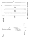
- FIG. 3 shows a cross section through the busbars embedded in insulating material. It can be seen that the individual busbars in different levels are arranged.
- the busbar L1 is located with its tongue 64 in the first level, d. H. on the top level.
- this busbar or tongue 64 has openings 80 through those shown in more detail below Grip contact springs 81 through.
- a beaks contact spring 81 just opens 80; that of Fig. 3b engages the contact spring 81 into a blind hole 82 located below the tongue 64.
- the tongue 68 is located in the plane below the tongue 64; through a through opening 83 a contact spring element 81 comes into contact with the tongue 68, the tongue 68 through an opening 84 in the tongue 68 which in one below located blind hole 85 engages. Contacting of the tongue 64 is avoided by that the through opening 83 is dimensioned sufficiently large.
- a tongue 70 could, for example, be provided in the level further below be, through the opening 86 through which the contact spring 81 is inserted; in Fig. 3e, the contact spring 81 with a busbar in the 4th level, i. H. contacted with the tongue of the neutral conductor 75, for example.
- Fig. 3 (3a to 3e) shows that the individual busbars in the insulating body 90 are embedded, access to openings 90,92,93 / 84,94 and 95 to the individual Has tongues.
- FIG. 2 shows the arrangement according to FIG. 3 in a schematic representation, where no four levels, but only three levels of busbars one above the other are shown lying.
- FIG. 2 also shows a contact element 96, which in the plane 1 and in the Level 3 busbars connected to each other. The reason why this is necessary, can be seen from Fig. 6.
- the one that receives the busbars Insulating material housing 100 which corresponds to the insulating material housing 90 of FIG. 8, has Openings 101, 102, 103, 104, 105 and 106 and openings 107, 108 and 109.
- FIG. 6 shows a section corresponding to FIG. 3 through a busbar housing ; there are a total of four busbar levels 110, 111, 112 and 113 intended.
- the busbar 110 located in the area of the opening 101 has an opening 114 which is smaller than the diameter of the hole 101.
- the busbar 111 has an opening 115 which is the same size than the opening 114, thus smaller than the hole 102.
- the busbar 112 has an opening 116, the inside diameter corresponds to the inner diameter 114 and 115. If a module with contact springs 3, inserted into openings 101, 102, 103, for example then these contact springs contact the busbar on the one hand 110, in addition the busbar 111 and the busbar 112.
- the busbar is located below these three busbars 110, 111 and 112 114; one recognizes that this busbar 113 openings 116, 117 and 118 owns; these openings 116 to 118 have the same diameter as that Opening 114, 115 and 116 and lie one above the other so that the phase of the busbar 110 by means of a contact piece, for example the contact piece 96 the busbar 113 can be placed.
- opening 107 inserted the contact piece, which the busbars 110 and 113 together combines.
- busbar 111 with the busbar 113 or the Busbar 112 can be contacted with the busbar 113.
- Fig. 6 a to the right of holes 101 to 106 are in a line therewith Holes 120, 121, 122, 123, 124 and 125 are provided; via busbar 113 can then be inserted into the holes 120 to 125 installation devices as needed be placed on the phase that is in the busbar 110, in the busbar 111 or in the busbar 112 is given.
- 11 shows a corresponding one Connection line 126 in dashed lines.
- FIG. 4 and 5 show a contact spring 81.
- a common contact carrier 130 On a common contact carrier 130 are prong-shaped tongues 131, 132, 133 and 134 which are formed against each other are bent, as can be seen from FIG. 9. There are to the right (see Fig. 4) bent tongues 131 and 133 and to the left bent tongues 132 and 134th
- Figures 7 to 10 show an embodiment of an installation device.
- the device is approximately T - or socket-shaped with a front side 140 and an attachment side 141 educated.
- 10 has two rotatably mounted double arm levers 150 and 151, with the lever arms 152 and 153 facing the fastening side are attacking springs 154 and 155 that separate the arms 152, 153 - and the others Press arms 156 and 157 against each other.
- the free ends of arms 156 and 157 have noses 158 and 159 to be facing one another; when assembling the Noses 158 and 159 behind the strips 148 and 149, the module with the bottom side 141 inserted in the direction of arrow 160 between the two double arm levers 51 and 151 becomes.
Landscapes
- Engineering & Computer Science (AREA)
- Manufacturing & Machinery (AREA)
- Microelectronics & Electronic Packaging (AREA)
- Installation Of Bus-Bars (AREA)
- Distribution Board (AREA)
Abstract
Es wird eine in einem Gehäuse untergebrachte elektrische Installationsverteilung beschrieben,
die einen in das Gehäuse eingeführten Zugangsleiter und zu einzelnen Verbrauchern
führende Abgangsleiter, elektrische Installationsgeräte, wie z. B. Fehlerstromschutzgeräten,
Leitungsschutzgeräten und dergleichen, die mit mit dem Zugangsleiter
und den Abgangsleitern verbundenen Stromschienen mittels einer Steckverbindung
verbindbar sind, und mit eine Tragplatte zur Halterung der Installationsgeräte
aufweist, wobei die Stromschienen unterhalb der Tragplatte angeordnet sind und
die Tragplatte Öffnungen aufweist, in die an den Installationsgeräten angeordnete
Steckelemente zu den Stromschienen hin einführbar sind. Die Stromschienen unterschiedlicher
Phase und Zu- und Abgängen sind in gleichen Ebenen gegeneinander und
voneinander isoliert angeordnet und in ein Isoliergehäuse eingebettet, vorzugsweise
eingegossen.

Description
Die Erfindung betrifft eine elektrische Installationsverteilung gemäß dem Oberbegriff
des Anspruches 1.The invention relates to an electrical installation distribution according to the preamble
of
Derartige Installationsverteilungen werden in Gebäuden zur Stromverteilung und Absicherung installiert ; in einem Installationsverteilergehäuse sind Leitungsschutzschalter, Fehlerstromschutzschalter und dgl. untergebracht, mit denen einzelne Verbraucher innerhalb eines Netzes geschützt werden sollen.Such distribution boards are used in buildings for power distribution and protection Installed ; in an installation distributor housing there are miniature circuit breakers, Residual current circuit breakers and the like. With which individual consumers within of a network are to be protected.
Üblicherweise enthalten derartige Gehäuse an ihrem Gehäuseboden Hutprofiltragschienen, auf denen die Schaltgeräte aufgeschnappt werden. Mittels Sammelschienen sind die Schaltgeräte phasenweise miteinander verbunden, wobei bei einphasigen Geräten lediglich eine Sammelschiene und bei mehrphasigen Anordnungen so genannte Sammelschienenblöcke verwendet werden, die ein Sammelschienen - Aufnahmegehäuse mit mehreren Kammern und in die Kammern eingesetzten Flachbandleiter aufweisen, wobei an den Flachbandleitern Anschlußfahnen vorgesehen sind, die in Anschlußklemmen an den Schaltgeräten einsteckbar und darin festklemmbar sind. Wenn mehrere Hutprofiltragschienen übereinander angeordnet sind, dann sind Verbindungsleiteranordnungen vorgesehen, mit denen die einzelnen Sammelschienen verbunden werden. Such housings usually contain top-hat rail on their housing base, on which the switchgear is snapped on. Using busbars the switching devices are connected to one another in phases, with single-phase devices only one busbar and so-called for multi-phase arrangements Busbar blocks are used that have a busbar receptacle with several chambers and have ribbon conductors inserted into the chambers, whereby connection tabs are provided on the ribbon conductors, which are in terminals can be plugged into the switchgear and clamped into it. If several hat profile support rails are arranged one above the other, then there are connecting conductor arrangements provided with which the individual busbars are connected become.
Aus der DE 196 28 957 A 1 ist eine Installationsverteilung bekannt, die ein Gehäuse aufweist, in dem Flachbandleiter untergebracht sind, an denen Anschlußfahnen angeformt sind, die Kontakttulpen tragen, in die an der Unterseite der Schaltgeräte angeordnete Steckerfahnen einsteckbar sind, wobei am Gehäuse eine Hutprofiltragschiene angebracht ist, auf die die Schaltgeräte aufgeschnappt werden. Beim Aufschnappen gelangen die Steckerfahnen durch im Gehäuse vorgesehene Öffnungen mit den Kontakttulpen in elektrisch leitenden Kontakt. Als Schaltgeräte werden solche verwendet, die eine übliche Schaltgeräteform besitzen ; lediglich auf der Unterseite ist die Stekkerfahne angebracht, anstatt Schraubanschlußklemmen, in die elektrische Leiter durch Öffnungen an den Schmalseiten der Schaltgeräte eingesteckt werden.An installation distribution is known from DE 196 28 957 A1, which is a housing has, are housed in the ribbon cable, on which terminal lugs are formed are, which wear contact tulips, in the arranged on the underside of the switchgear Plug tabs can be inserted, with a top-hat mounting rail attached to the housing on which the switchgear is snapped on. When snapping the connector lugs through openings provided in the housing with the contact tulips in electrically conductive contact. Switchgear used are which have a conventional switchgear shape; the Stekker flag is only on the underside attached, instead of screw terminals, into the electrical conductor Openings are inserted on the narrow sides of the switchgear.
Mit dieser Anordnung wird im Vergleich zu hergebrachten Verteilungen schon eine erhebliche Montageerleichterung erreicht, insoweit als wenigstens auf der Zugangsseite des Schaltgerätes das Festklemmen eines elektrischen Leiters oder einer Anschlußfahne einer Sammelschiene mittels eines Werkzeuges nicht mehr erforderlich ist.With this arrangement, a considerable amount becomes in comparison with traditional distributions Ease of assembly achieved, in so far as at least on the access side of the switching device, the clamping of an electrical conductor or a connecting lug a busbar using a tool is no longer required.
In die Verteilung wird eine Zugangsleitung eingeführt, die mit den Sammelschienen verbunden wird ; die den einzelnen Schaltgeräten zugeordneten Abgangsleitungen sind innerhalb des Installationsverteilergehäuses verlegt und aus dem Gehäuse herausgeführt, wobei die Abgangsleitungen an die Zuleitungen zu den Verbrauchern angeschlossen werden. Hier können sich durch Verwechselungen Fehlanschließungen ergeben, beispielsweise so, dass ein mittels eines Fehlerstromschutzschalters abzusichernder Verbraucher irrtümlicherweise an einen Leitungsschutzschalter angeschlossen wird.An access line with the busbars is introduced into the distribution is connected; are the outgoing lines assigned to the individual switching devices laid within the distribution box and led out of the housing, the outgoing lines connected to the supply lines to the consumers become. Here, incorrect connections can result from mistakes, For example, such that one to be protected by means of a residual current circuit breaker Consumer mistakenly connected to a circuit breaker becomes.
Aufgabe der Erfindung ist es, eine Installationsverteilung der eingangs genannten Art zu schaffen, bei der die Montage noch weiter vereinfacht wird und Fehlanschließungen vermieden werden.The object of the invention is an installation distribution of the type mentioned to create, in which the assembly is simplified even further and incorrect connections be avoided.
Diese Aufgabe wird erfindungsgemäß durch die Merkmale des Anspruches 1 gelöst.This object is achieved by the features of
Erfindungsgemäß sind die Stromschienen unterschiedlicher Phasen in gleichen Ebenen phasenweise isoliert voneinander angeordnet, und sind dabei in einen Isolierkörper eingebettet, vorzugsweise eingegossen.According to the invention, the busbars of different phases are in the same plane arranged in phases isolated from each other, and are in an insulating body embedded, preferably cast in.
Jeder Stromschiene kann dabei für jede Phase einen quer zur Anreihrichtung der Geräte verlaufenden Verbindungsabschnitt aufweisen, an dem eine der Anzahl der Installationsgeräte - Reihen entsprechende Anzahl von Zungen angebracht sind, die unterhalb der Geräte verlaufen und die die Aufnahmeöffnung für Steckelemente an den Installationsgeräten aufweisen. Die Stromschiene für den Neutralleiter weist ebenfalls einen quer zur Anreihrichtung der Installationsgeräte verlaufenden Verbindungsabschnitt auf, an dem eine der Anzahl der Installationsgeräte - Reihen entsprechende Anzahl von Zungen angebracht sind, die unterhalb der Installationsgeräte verlaufen und die die Aufnahmeöffnungen für die Steckeelemente aufweisen.Each conductor rail can have one for each phase, transverse to the direction in which the devices are connected have extending connecting section, at which one of the number of installation devices - Rows of appropriate number of tongues are attached below of the devices and the opening for plug-in elements on the installation devices exhibit. The conductor rail for the neutral conductor also points a connecting section running transversely to the direction of the installation devices on the number corresponding to the number of installation device rows are attached by tongues that run below the installation devices and which have the receiving openings for the plug elements.
Die Stromschienen können dabei übereinander angeordnet sein, wobei die Zungen unterschiedlicher Phasen gegeneinander versetzt sind.The busbars can be arranged one above the other, the tongues different phases are offset from each other.
Weitere vorteilhafte Ausgestaltungen der Erfindung, insbesondere Ausgestaltungen der einzelnen Stromschienen, sind den weiteren Unteransprüchen zu entnehmen.Further advantageous refinements of the invention, in particular refinements of the individual busbars can be found in the further subclaims.
Anhand der Zeichnung, in der einige Ausführungsbeispiele der Erfindung dargestellt sind, sollen die Erfindung sowie weitere vorteilhafte Ausgestaltungen und Verbesserungen und weitere Vorteile näher erläutert und beschrieben werden.Using the drawing, in which some embodiments of the invention are shown are, the invention and other advantageous refinements and improvements and further advantages are explained and described in more detail.
Es zeigen:
Es sei Bezug genommen auf die Fig. 1.Reference is made to FIG. 1.
Fig. 1 zeigt eine Aufsicht auf eine Stromschienenanordnung, die in ein Stromschienengehäuse eingesetzt werden kann, wie es in den Fig. 2 und 3 dargestellt ist.Fig. 1 shows a plan view of a busbar arrangement, which is in a busbar housing can be used, as shown in FIGS. 2 and 3.
Die Stromschiene L1 besitzt ein senkrecht zur Anreihrichtung der Installationsgeräte
verlaufendes Verbindungsstück 61, an dem senkrecht dazu Zungen 62, 63 und 64 angeformt
sind. Die Länge des Verbindungsstückes 61 entspricht dem Abstand der Installationsgerätereihen
voneinander und die Länge der Zungen 62 bis 64 entspricht der
Länge der angereihten Installationsschaltgeräte in Anreihrichtung gesehen.The busbar L1 has a perpendicular to the direction of the installation devices
extending connecting
In ähnlicher Weise ist die Stromschiene L2 aufgebaut. Sie besitzt einen Verbindungssteg
65, an dem eine der Anzahl der Phasen entsprechende Anzahl von Zungen 66,67
und 68 angeformt ist. Die Zungen 66 und 62 67 und 63,68 und 64 verlaufen parallel
zueinander und springen von ihren Verbindungsstegen in die gleiche Richtung vor.The busbar L2 is constructed in a similar manner. It has a connecting
Diesen beiden Phasenleitern ist ein dritter Phasenleiter L3 zugeordnet zu, der ein Verbindungsteil
69 besitzt, an dem Zungen 70,71 und 72 angeformt sind. Das Verbindungsteil
69 befindet sich die in der Nähe der Enden der Zungen 62,66 ; 63,67 ; 64,68
und die Zungen 70,71 und 72 springen in entgegengesetzte Richtung zu den Verbindungsstücken
61 und 65 vor. A third phase conductor L3, which is a connecting part, is assigned to these two phase conductors
69 has, on which
Zugeordnet zu den drei Phasenleitern ist ein Neutralleiter N, der einen ähnlichen Aufbau
besitzt, mit einem Verbindungsstück 73 unterhalb des Verbindungsstück des 69
und mit den die gleiche Richtung wie die Zungen 70,71 und 72 vorspringenden Zungen
74,75,76,77,78,79,80,81. Weiterhin ist als PE - Leiter eine Platte vorgesehen, die unterhalb
der einzelnen Phasenschienen und des Neutralleiters liegt.Associated with the three phase conductors is a neutral conductor N, which has a similar structure
has, with a
Die Fig. 3 zeigt einen Querschnitt durch die in Isolierstoffmaterial eingebetteten Stromschienen.
Man erkennt, dass die einzelnen Stromschienen in unterschiedlichen Ebenen
angeordnet sind. Beispielsweise die Stromschiene L1 befindet sich mit ihrer Zunge 64
in der ersten Ebene, d. h. in der obersten Ebene. Man erkennt, dass diese Sammelschiene
bzw. Zunge 64 Öffnungen 80 aufweist, durch die weiter unten näher dargestellte
Kontaktfedern 81 hindurch greifen. In der Zeichnung ganz links Fig. 3 a schnäbelt
die Kontaktfeder 81 die Öffnung 80 gerade an ; die der Fig. 3b greift die Kontaktfeder
81 in ein unterhalb der Zunge 64 befindliches Sackloch 82 ein.3 shows a cross section through the busbars embedded in insulating material.
It can be seen that the individual busbars in different levels
are arranged. For example, the busbar L1 is located with its
In der Ebene unterhalb der Zunge 64 befindet sich die Zunge 68 ; durch eine Durchgangsöffnung
83 hindurch kommt ein Kontaktfederelement 81 mit der Zunge 68 in Berührung,
wobei die Zunge 68 durch eine Öffnung 84 in der Zunge 68 die in ein darunter
befindliches Sackloch 85 eingreift. Eine Kontaktierung der Zunge 64 wird dadurch vermieden,
daß die Durchgangsöffnung 83 ausreichend groß bemessen wird.The
In der weiter darunter liegenden Ebene könnte beispielsweise eine Zunge 70 vorgesehen
sein, durch deren Öffnung 86 hindurch die Kontaktfeder 81 hindurch gesteckt wird ;
bei der Fig. 3e ist die Kontaktfeder 81 mit einer Sammelschiene in der 4. Ebene, d. h.
mit der Zunge beispielsweise des Neutralleiters 75 kontaktiert .A
Die Fig. 3 (3a bis 3e) zeigt, dass die einzelnen Sammelschienen in den Isolierstoffkörper
90 eingebettet sind, der Zugang zu Öffnungen 90,92,93/84,94 und 95 zu den einzelnen
Zungen aufweist. Fig. 3 (3a to 3e) shows that the individual busbars in the
Die Zeichnung Fig. 2 zeigt die Anordnung gemäß Fig. 3 in schematischer Darstellung, wobei keine vier Ebenen, sondern lediglich drei Ebenen von Sammelschienen übereinander liegend dargestellt sind.2 shows the arrangement according to FIG. 3 in a schematic representation, where no four levels, but only three levels of busbars one above the other are shown lying.
Die Kontaktfeder der Fig. 2 besitzt die gleiche Bezugsziffer 81, obwohl der Aufbau geringfügig
anders ist, um die Ähnlichkeit bezüglich der Funktion darzustellen.2 has the
Die Fig. 2 zeigt weiterhin ein Kontaktelement 96, welches in der Ebene 1 und in der
Ebene 3 befindliche Sammelschienen miteinander verbindet. Der Grund, warum dieses
erforderlich ist, ist aus der Fig. 6 ersichtlich. Das die Sammelschienen aufnehmende
Isolierstoffgehäuse 100, welches dem Isolierstoffgehäuse 90 der Fig. 8 entspricht, besitzt
Öffnungen 101, 102, 103, 104, 105 und 106 sowie Öffnungen 107, 108 und 109.FIG. 2 also shows a
Die Fig. 6 zeigt einen der Fig. 3 entsprechenden Schnitt durch ein Sammelschienengehäuse
; hierbei sind insgesamt vier Sammelschienenebenen 110, 111, 112 und 113
vorgesehen. Die im Bereich der Öffnung 101 befindliche Sammelschiene 110 besitzt
einen Durchbruch 114, der kleiner ist als der Durchmesser des Loches 101. In dem
Durchbruch 102 besitzt die Sammelschiene 111 einen Durchbruch 115, der gleich groß
ist als der Durchbruch 114, somit kleiner als das Loch 102 ist. Im Bereich des Loches
103 besitzt die Sammelschiene 112 einen Durchbruch 116, dessen Innendurchmesser
dem Innendurchmesser 114 und 115 entspricht. Wenn nun ein Modul mit Kontaktfedern,
beispielsweise Kontaktfingern gemäß Fig. 3, in die Öffnungen 101, 102, 103 eingefügt
werden, dann kontaktieren diese Kontaktfedern einerseits die Sammelschiene
110, darüber hinaus die Sammelschiene 111 und die Sammelschiene 112.FIG. 6 shows a section corresponding to FIG. 3 through a busbar housing
; there are a total of four
Unterhalb dieser drei Sammelschienen 110, 111 und 112 befindet sich die Sammelschiene
114 ; man erkennt, dass diese Sammelschiene 113 Öffnungen 116,1 117 und
118 besitzt; diese Öffnungen 116 bis 118 besitzen den gleichen Durchmesser wie die
Öffnung 114, 115 und 116 und liegen übereinander, sodass die Phase der Sammelschiene
110 mittels eines Kontaktstückes, beispielsweise des Kontaktstückes 96, auf
die Sammelschiene 113 gelegt werden kann. Zu diesem Zweck wird in die Öffnung 107
das Kontaktstück eingefügt, welches die Sammelschienen 110 und 113 miteinander
verbindet. The busbar is located below these three
In gleicher Weise könnte die Sammelschiene 111 mit der Sammelschiene 113 bzw. die
Sammelschiene 112 mit der Sammelschiene 113 kontaktiert werden.In the same way, the
In der Fig. 6 a sind rechts von Löchern 101 bis 106 in einer Linie damit liegend weitere
Löcher 120, 121, 122 123, 124 und 125 vorgesehen ; über die Sammelschiene 113
können dann in die Löcher 120 bis 125 eingesteckte Installationsgeräte je nach Bedarf
auf die Phase gelegt werden, die in der Sammelschiene 110, in der Sammelschiene
111 oder in der Sammelschiene 112 gegeben ist. Die Fig. 11 zeigt eine entsprechende
Verbindungsleitung 126 in strichlierter Darstellung.In Fig. 6 a to the right of
Die Fig. 4 und 5 zeigen eine Kontaktfeder 81. An einem gemeinsamen Kontaktträger
130 sind zinken - förmig Zungen 131,1 132,1 133 und 134 angeformt, die gegeneinander
verbogen sind, wie aus der Fig. 9 ersichtlich. Dort sind nach rechts (siehe Fig. 4)
ausgebogen die Zungen 131 und 133 und nach links ausgebogen die Zungen 132 und
134.4 and 5 show a
Die Figuren 7 bis 10 zeigen eine Ausgestaltung eines Installationsgerätes. Das Gerät
ist etwa T - oder sockelförmig mit einer Frontseite 140 und einer Befestigungsseite 141
ausgebildet. An der Frontseite befindet sich eine Fläche mit Bedienelementen 142. Auf
der Befestigungsseite ragen Kontaktfedern 81 in einer entsprechenden Zuordnung zueinander.
An den Breitseiten 142 und 143 schließen Stege 144 und 145 an, die in der
Ebene der Breitseiten liegen und zur Führung des Gerätes im Gehäuse der Sammelschienen
dienen.Figures 7 to 10 show an embodiment of an installation device. The device
is approximately T - or socket-shaped with a
An denen Schmalseiten 146 und 147 sind vorspringende Nasen 148,1 149 angeformt,
über die das Gerät mittels der Geräteverriegelung gemäß Fig. 10 fixiert werden kann.
Die Anordnung gemäß Fig. 10 besitzt zwei drehbar gelagerte Doppelarmhebel 150 und
151, wobei an den Hebelarmen 152 und 153, die der Befestigungsseite zugewandt
sind, Federn 154 und 155 angreifen, die die Arme 152, 153 auseinander - und die anderen
Arme 156 und 157 gegeneinander drücken. Die freien Enden der Arme 156 und
157 besitzen aufeinanderzuweisende Nasen 158 und 159 ; bei der Montage greifen die
Nasen 158 und 159 hinter die Leisten 148 und 149, wobei das Modul mit der Bodenseite
141 in Pfeilrichtung 160 zwischen die beiden Doppelarmhebel 51 und 151 eingefügt
wird.On the
Claims (9)
Applications Claiming Priority (2)
| Application Number | Priority Date | Filing Date | Title |
|---|---|---|---|
| DE10146503 | 2001-09-21 | ||
| DE10146503A DE10146503A1 (en) | 2001-09-21 | 2001-09-21 | Electrical installation distribution |
Publications (2)
| Publication Number | Publication Date |
|---|---|
| EP1296431A2 true EP1296431A2 (en) | 2003-03-26 |
| EP1296431A3 EP1296431A3 (en) | 2004-10-27 |
Family
ID=7699756
Family Applications (1)
| Application Number | Title | Priority Date | Filing Date |
|---|---|---|---|
| EP02020192A Withdrawn EP1296431A3 (en) | 2001-09-21 | 2002-09-10 | Bus bar assembly |
Country Status (3)
| Country | Link |
|---|---|
| US (1) | US20030067756A1 (en) |
| EP (1) | EP1296431A3 (en) |
| DE (1) | DE10146503A1 (en) |
Cited By (1)
| Publication number | Priority date | Publication date | Assignee | Title |
|---|---|---|---|---|
| WO2022258191A1 (en) | 2021-06-11 | 2022-12-15 | Duplico D.O.O. | Kit used for automated assembling or disassembling of laminated electric circuits |
Families Citing this family (7)
| Publication number | Priority date | Publication date | Assignee | Title |
|---|---|---|---|---|
| DE102005015945B4 (en) * | 2005-04-07 | 2015-07-02 | Abb Ag | Contact device for a two- or multi-phase busbar arrangement |
| DE102006060569A1 (en) * | 2006-12-19 | 2008-07-10 | Friedrich Göhringer Elektrotechnik GmbH | Contact tab for busbar, has electrically conductive elongated body arrangeable on pole bar with one end of body such that another end of body forms free side-piece, which exhibits clamping device that is formed as springy element |
| DE102008037966A1 (en) | 2008-08-13 | 2010-02-18 | Siemens Aktiengesellschaft | Method for producing a multi-pole connection or exit point for a conductor rail with coaxially arranged, tubular partial conductors |
| DE102010050654B4 (en) * | 2010-11-09 | 2017-03-16 | Abb Ag | Arrangement of conductors for connection of a circuit breaker |
| DE102012016133B4 (en) * | 2012-08-15 | 2014-09-11 | Diethelm Bienhaus | Electrical installation distribution with fasteners and methods for identification and assignment of installation equipment and fasteners |
| WO2019201419A1 (en) * | 2018-04-16 | 2019-10-24 | Abb Schweiz Ag | Apparatus for electrically interconnecting two laminated multi-phase busbars and switchgear cabinet including such an apparatus |
| DE102019218210B4 (en) * | 2019-11-25 | 2022-12-29 | Lenze Swiss Ag | Electric device |
Family Cites Families (14)
| Publication number | Priority date | Publication date | Assignee | Title |
|---|---|---|---|---|
| US1736028A (en) * | 1922-10-21 | 1929-11-19 | Metropolitan Electric Mfg Comp | Electric panel or distribution board |
| DE1590329B1 (en) * | 1966-01-21 | 1972-05-04 | Ellison George Ltd | Electrical distribution device |
| NL8801467A (en) * | 1988-06-07 | 1990-01-02 | Holec Syst & Componenten | CONTROL BOX FOR ELECTRICAL INSTALLATIONS. |
| DE8813533U1 (en) * | 1988-10-28 | 1988-12-15 | Asea Brown Boveri AG, 6800 Mannheim | Insulated busbar package |
| US5139426A (en) * | 1991-12-11 | 1992-08-18 | Amp Incorporated | Adjunct power connector |
| DE4327715A1 (en) * | 1993-08-18 | 1995-02-23 | Abb Patent Gmbh | Device for supplying electrical energy to at least one electrical installation device |
| DE4438805C1 (en) * | 1994-10-31 | 1996-03-07 | Weidmueller Interface | Field bus connection module for coupling of local bus conductor of machine and plant control systems |
| DE19628957A1 (en) * | 1996-07-18 | 1998-01-22 | Abb Patent Gmbh | Connection device for electrical installation devices |
| US6002580A (en) * | 1996-12-09 | 1999-12-14 | Power Distribution Products International | Circuit breaker power distribution panel |
| DE29804284U1 (en) * | 1998-03-11 | 1998-05-07 | Weidmüller Interface GmbH & Co, 32760 Detmold | Control system for electronic control and automation systems |
| DE19859717A1 (en) * | 1998-12-23 | 2000-06-29 | Moeller Gmbh | Rapid assembly wiring system for electrical cabinets has current rail system for supplying electrical power with rails embedded in channel, and output points for output lines with contacts |
| DE19964156B4 (en) * | 1999-01-25 | 2004-07-15 | Weidmüller Interface Gmbh & Co. | Electric device |
| US6560123B1 (en) * | 1999-06-04 | 2003-05-06 | Astec International Limited | Plug-in GMT fuse block |
| US6315580B1 (en) * | 1999-06-04 | 2001-11-13 | Astec International Limited | PCB connector module for plug-in circuit breakers and fuses |
-
2001
- 2001-09-21 DE DE10146503A patent/DE10146503A1/en not_active Ceased
-
2002
- 2002-09-10 EP EP02020192A patent/EP1296431A3/en not_active Withdrawn
- 2002-09-23 US US10/252,289 patent/US20030067756A1/en not_active Abandoned
Cited By (1)
| Publication number | Priority date | Publication date | Assignee | Title |
|---|---|---|---|---|
| WO2022258191A1 (en) | 2021-06-11 | 2022-12-15 | Duplico D.O.O. | Kit used for automated assembling or disassembling of laminated electric circuits |
Also Published As
| Publication number | Publication date |
|---|---|
| EP1296431A3 (en) | 2004-10-27 |
| DE10146503A1 (en) | 2003-04-10 |
| US20030067756A1 (en) | 2003-04-10 |
Similar Documents
| Publication | Publication Date | Title |
|---|---|---|
| EP2255410B1 (en) | Modular terminal, and modular terminal block | |
| DE102008017245B4 (en) | Plug-in adapter for an electrical switching device | |
| DE69017980T2 (en) | Socket unit for a modular energy distribution system for furniture. | |
| DE102010032383B4 (en) | Busbar connector and busbar system with at least two adjacent busbars and a busbar connector | |
| DE69008139T2 (en) | Kit for electrically connecting a plurality of modular circuit breakers simultaneously. | |
| EP3111515B1 (en) | Terminal strip and terminal strip block | |
| EP0639877B1 (en) | Device for supplying at least one electric installation appliance with electric energy | |
| EP0645841A1 (en) | Terminals for side by side mounting | |
| DE68903836T2 (en) | CONSUMER UNITS. | |
| EP1749336B1 (en) | Modular current distributor for high currents | |
| EP0379662B1 (en) | Socket block | |
| EP0821454B1 (en) | Connecting device for electrical installation apparatus | |
| EP0454016A2 (en) | Mains clamp fixed on a standardized support rail | |
| EP1296431A2 (en) | Bus bar assembly | |
| DE68912040T2 (en) | Device for connecting modular electrical devices by means of a bridging comb and method of manufacturing such a comb. | |
| EP1472766B1 (en) | Connecting or distributing device for electrical installation equipment | |
| DE68906737T2 (en) | Device for fastening a modular electrical device on a profile carrier. | |
| EP0080646B1 (en) | Base for a miniature relay | |
| DE102005023452B4 (en) | Mounting and wiring system for electrical function modules, in particular for switching devices | |
| EP1353350B1 (en) | Auxiliary switch | |
| DE10340212B4 (en) | manifold assembly | |
| EP1787358B1 (en) | Power feed module with cage clamp terminals | |
| EP1296426A2 (en) | Electrical distribution installation | |
| DE102016122437B4 (en) | contacting device | |
| DE102023117907B4 (en) | DEVICE CARRIER MODULE AND MOUNTING PANEL SYSTEM WITH SUCH A DEVICE CARRIER MODULE |
Legal Events
| Date | Code | Title | Description |
|---|---|---|---|
| PUAI | Public reference made under article 153(3) epc to a published international application that has entered the european phase |
Free format text: ORIGINAL CODE: 0009012 |
|
| AK | Designated contracting states |
Kind code of ref document: A2 Designated state(s): AT BE BG CH CY CZ DE DK EE ES FI FR GB GR IE IT LI LU MC NL PT SE SK TR Designated state(s): AT BE BG CH CY CZ DE DK EE ES FI FR GB GR IE IT LI LU MC NL PT SE SK TR |
|
| AX | Request for extension of the european patent |
Extension state: AL LT LV MK RO SI |
|
| PUAL | Search report despatched |
Free format text: ORIGINAL CODE: 0009013 |
|
| AK | Designated contracting states |
Kind code of ref document: A3 Designated state(s): AT BE BG CH CY CZ DE DK EE ES FI FR GB GR IE IT LI LU MC NL PT SE SK TR |
|
| AX | Request for extension of the european patent |
Extension state: AL LT LV MK RO SI |
|
| 17P | Request for examination filed |
Effective date: 20041001 |
|
| AKX | Designation fees paid |
Designated state(s): DE FR GB IT |
|
| STAA | Information on the status of an ep patent application or granted ep patent |
Free format text: STATUS: THE APPLICATION IS DEEMED TO BE WITHDRAWN |
|
| 18D | Application deemed to be withdrawn |
Effective date: 20120403 |