EP1296181A2 - Appareil de lecture pour image radiographique - Google Patents
Appareil de lecture pour image radiographique Download PDFInfo
- Publication number
- EP1296181A2 EP1296181A2 EP02256393A EP02256393A EP1296181A2 EP 1296181 A2 EP1296181 A2 EP 1296181A2 EP 02256393 A EP02256393 A EP 02256393A EP 02256393 A EP02256393 A EP 02256393A EP 1296181 A2 EP1296181 A2 EP 1296181A2
- Authority
- EP
- European Patent Office
- Prior art keywords
- ray image
- read
- read heads
- light
- head
- Prior art date
- Legal status (The legal status is an assumption and is not a legal conclusion. Google has not performed a legal analysis and makes no representation as to the accuracy of the status listed.)
- Withdrawn
Links
Images


Classifications
-
- G—PHYSICS
- G01—MEASURING; TESTING
- G01N—INVESTIGATING OR ANALYSING MATERIALS BY DETERMINING THEIR CHEMICAL OR PHYSICAL PROPERTIES
- G01N23/00—Investigating or analysing materials by the use of wave or particle radiation, e.g. X-rays or neutrons, not covered by groups G01N3/00 – G01N17/00, G01N21/00 or G01N22/00
- G01N23/02—Investigating or analysing materials by the use of wave or particle radiation, e.g. X-rays or neutrons, not covered by groups G01N3/00 – G01N17/00, G01N21/00 or G01N22/00 by transmitting the radiation through the material
- G01N23/04—Investigating or analysing materials by the use of wave or particle radiation, e.g. X-rays or neutrons, not covered by groups G01N3/00 – G01N17/00, G01N21/00 or G01N22/00 by transmitting the radiation through the material and forming images of the material
-
- G—PHYSICS
- G03—PHOTOGRAPHY; CINEMATOGRAPHY; ANALOGOUS TECHNIQUES USING WAVES OTHER THAN OPTICAL WAVES; ELECTROGRAPHY; HOLOGRAPHY
- G03B—APPARATUS OR ARRANGEMENTS FOR TAKING PHOTOGRAPHS OR FOR PROJECTING OR VIEWING THEM; APPARATUS OR ARRANGEMENTS EMPLOYING ANALOGOUS TECHNIQUES USING WAVES OTHER THAN OPTICAL WAVES; ACCESSORIES THEREFOR
- G03B42/00—Obtaining records using waves other than optical waves; Visualisation of such records by using optical means
- G03B42/08—Visualisation of records by optical means
Definitions
- the present invention relates to an X-ray image reader for reading an X-ray image stored in an X-ray image-storing member having an X-ray storing surface formed of, for example, a storage fluorescent member.
- the X-ray image-storing member formed by a storage fluorescent member has been known.
- the specimen is irradiated with X-ray and the X-ray image-storing member is exposed by X-ray emitted from the specimen, for example, diffracted X-ray or scattered X-ray. Therefore, a latent image of energy is formed in an X-ray receiving surface of the X-ray image storing member at a coordinates position, which corresponds to a diffraction angle of the diffracted X-ray or the scattered X-ray thus generated.
- the storage fluorescent member has the nature of holding a latent image of energy at a position thereof to which X-ray impinges and the nature of converting the latent image of energy into light when a portion thereof which holds the latent image is irradiated with emission stimulating light, such as laser light. Therefore, it is possible to know intensity of X-ray contributed to the formation of the latent image by detecting externally emitted light from the storage fluorescent member when the storage fluorescent member holding the latent image of energy is irradiated by laser light. Further, it is possible to know the diffraction angle of X-ray contributed to the formation of latent image by the coordinates of the storage fluorescent member from which light is emitted.
- a double-head type X-ray image reader 100 which is shown in FIG. 10.
- a first read head 101a and a second read head 101b are arranged symmetrically about a center axis X0 and laser light from an emitting optical system 102 including a laser light source is divided so that laser light portions are emitted externally through the first and second read heads 101a and 101b, respectively.
- Each of the first read head 101a and the second read head 101b can take externally supplied light therein.
- the light thus taken into the read head is guided to a receiving optical system 103 including a photoelectric converter and then converted into an electric signal by the photoelectric converter.
- the X-ray image storing member 104 takes in the form of a concaved and semi-cylindrical configuration and the center axis X0, which is a rotation center of the first and second read heads 101a and 101b is positioned at substantially a center of the semi-cylindrical X-ray image storing member 104.
- the first and second read heads 101a and 101b are rotated about the axis line X0 in a direction shown by an arrow A, while the whole X-ray image reader 100 is moved in parallel to the axis line X0 in a direction shown by an arrow B.
- the first and second read heads 101a and 101b With the rotation of the first and second read heads 101a and 101b in the arrow direction A and the straight vertical movement of the whole X-ray image reader in the arrow direction B, the first and second read heads 101a and 101b are alternatively moved to a position opposing to the X-ray image storing member 104, so that a wide area of the X-ray image storing member 104 is scanned by these read heads.
- laser light from the first read head 101a or the second read head 101b scans a surface of the X-ray image storing member 104 and, when the laser light scans a portion of the surface in which a latent image of energy is formed, fluorescent light is emitted from that portion.
- This light is taken in the receiving optical system 103 through the first read head 101a or the second read head 101b and converted into an electric signal, on the basis of a level of which intensity of the light can be obtained. Since the intensity of light corresponds to intensity of X-ray contributed to a formation of the latent image of energy, it is possible to know the intensity of X-ray by measuring the intensity of light.
- the conventional double-head type X-ray image reader 100 constructed as mentioned above makes it possible to perform a high speed reading since two read heads 101a and 101b are used alternatively and effectively.
- this double-head type X-ray image reader 100 requires a processing technique for matching the two data obtained alternatively by the read heads 101a and 101b with onereference level. Despite use of such technique a complete processing may not be achieved. Therefore, the conventional double-head type X-ray image reader may not perform a highly precise measurement.
- the present invention was made in view of the above-mentioned problem and an object of the present invention is to provide an X-ray image reader for reading an X-ray image by using a plurality of read heads, which is capable of performing a precise reading.
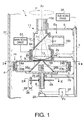
- FIG. 1 illustrates a cross sectional structure of a double-head type X-ray image reader 1 according to the present invention.
- the x-ray image reader 1 includes a rotary mechanism 4 rotatably supported by a main frame 3 through bearings 2a and 2b so as to rotate around an axis line X0.
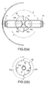
- An X-ray image-storing member 17 to be read takes in the form of a semi-cylindrical configuration having a center coincident with the axis line X0 as shown in FIG. 2(a), which shows a cross section taken along a line II - II in FIG. 1.
- the X-ray image-storing member 17 has an X-ray receiving surface formed of a storage fluorescent member.
- the rotary mechanism 4 includes a cylindrical laser light input portion 6 supported by the bearing 2b, a head portion 7 provided on an upper end portion of the laser light input portion 6 and a cylindrical light output portion 8 provided on an upper surface of the head and supported by the bearing 2a.
- the head portion 7 takes in the form of a long square tube extending in a direction orthogonal to the axis line X0.
- An upper end portion 8a of the light output portion 8 is opened.
- a first read head H1 including lenses 23a and 24a is provided on one end of the head portion 7 and a second read head H2 including lenses 23b and 24b is provided on the other end of the head portion 7. That is, the read heads H1 and H2 are symmetrically arranged on the read portion 7 about the axis line X0 with angular interval of 180 degrees. Although the angular interval of 180 degrees should be set as strictly as possible, there may be deviated from 180 degrees practically. In such case, it is preferable to correct a result of measurement correspondingly to an amount of deviation.
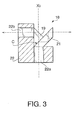
- a beam splitter 18 is provided within the head portion 7 and above the laser light input portion 6.
- the beam splitter 18 is rotated about the axis line X0 integrally with the head portion 7.
- the beam splitter 18 is constructed with a prism 19 having a triangular cross section and a slope surface C, a prism 21 having a trapezoidal cross section and a bottom surface bonded to the surface C of the prism 19 and a base 22 onto which the prisms 19 and 21 are fixed by bonding or other means.
- a portion of light inputted through a light input opening 22a formed in the base 22 is transmitted through the interface C between the prisms 19 and 21, and reflected at inner surface of the triangle prism 19 to outputted externally through a light output opening 22b formed in the base 22.
- the portion of the input light is directed to the first read head H1 in FIG. 1.
- the other portion of light inputted through the opening 22a is reflected by the interface C , transmitted through the trapezoidal prism 21 and then outputted in a direction opposite to the output direction of the one light portion.
- the oppositely directed light portion is emitted toward the second read head H2 in FIG. 1.
- a dichroic mirror 26a is provided between the first read head H1 and the beam splitter 18 within the head portion 7 and a dichroic mirror 26b is provided between the second read head H2 and the beam splitter 18.
- Each of the dichroic mirrors allows light from the beam splitter 18 to pass to the corresponding read head. Further, each dichroic mirror reflects light, which is taken in by the corresponding read head to be directed to the beam splitter 18, to a photo-detector 11.
- the photo-detector 11 is fixedly supported by the main frame 3 through a bracket 9.
- the photo-detector 11 includes a frame 12 having a lower end portion loosely fitted in the light output portion 8 of the rotary mechanism 4 and an upper portion supported by the main frame 3 through a bracket 9, a condenser lens 13 provided in a lower end portion of the frame 12, a filter 14 provided on a downstream of the condenser lens 13 in a propagation direction of light (meaning above the condenser lens 13 in Fig. 1), a first photo-tube 16a provided above the filter 14 to receive light transmitted therethrough and a second photo-tube 16b provided to receive light reflected by the filter 14.
- the filter 14 may be formed of a typical transparent member such as glass plate and functions to pass about 90% of incident light therethrough and guide it to the first phototube 16a and to reflect the remaining light to the second phototube 16b.
- the phototubes 16a and 16b are opto-electric conversion elements having known structure and function to output electric signals corresponding to intensities of lights incident thereon.
- the X-ray image reader 1 further includes a laser light generator 27 having a laser light source Fo therein.
- the laser light generator 27 emits laser light when a power source thereof is turned ON and stops the emission of laser light by turning the power source OFF.
- a prism 28 is provided below the laser light input portion 6 of the rotary mechanism 4. The laser light emitted from the laser light generator 27 is reflected by the prism 28 and taken in the laser light input portion 6.
- a rotary disk 29 for generating pulse signal is provided at a suitable position on an outer peripheral surface of the laser light input portion 6.
- the rotary disk 29 takes in the form of a circular disk including a semi circular large diameter portion 31a and a semi circular small diameter portion 31b.
- a first slit 32a is formed in substantially a center of an outer periphery of the large diameter portion 31a and extends to the axis line X0 by a limited length and a second slit 32b is formed in substantially a center of an outer periphery of the large diameter portion 31b and extends to the axis line X0 by a length slightly shorter than the length of the slit 32a so that radial positions of bottoms of the slits 32a and 32b become substantially equal.
- the first slit 32a corresponds in position to the first read head H1 and the second slit 32b corresponds to the second read head H2.
- a sensor 36 composed of a light-emitting element 33 and a light-receiving element 34 is provided at a suitable position with respect to the periphery of the rotary disk 29.
- the sensor 36 distinguishes the first and second slits 32a and 32b on the basis of the difference in diameter between the large and small diameter portions 31a and 31b of the rotary disk 29 when the rotary mechanism 4 rotates, that is, when the first and second read heads H1 and H2 rotate, and outputs electric signals correspondingly thereto.
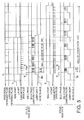
- the censor 36 generates an index signal pulse and an EVEN signal pulse in a timing chart shown in FIG. 5 as reference pulses.
- the index pulse is generated every half rotation of each of the first and second read heads H1 and H2, that is, at every time when each of the read heads H1 and H2 rotates by 180 degrees.
- the EVEN pulse is generated every time when the rotary mechanism 4 makes one rotation, that is, rotates by 360 degrees. That is, the EVEN pulse is generated at a time when the rotary mechanism 4 rotates by 360 degree, 720 degrees, 1080 degrees and so on.
- the EVEN pulse is generated when the first read head H1 scans the X-ray image-storing member 17.
- a main scan rotary drive 37 is connected to the rotary mechanism 4 including the first and second read heads H1 and H2.
- the main scan rotary drive 37 rotates the read heads H1 and H2 about the axis line X0 to scan the X-ray image storing member 17 laterally in a main scan direction in a plane perpendicular to the axis line X0.
- the main scan rotary drive 37 may be constructed with a drive system having an arbitrary structure.
- the drive system may be constructed with a motor such as a pulse motor or a servomotor whose rotation speed can be controlled as a drive source and a power transmission system constructed with such as belt and gears for transmitting the rotation of the motor to the rotary mechanism 4.
- a sub scan drive 38 for sub-scanning the X-ray image storing member 17 is connected to the main frame 3, which supports the whole X-ray image reader 1.
- the sub scan drive 38 moves the main frame 3 in a sub scan direction parallel to the axis line X0 to move the read heads H1 and H2 in a longitudinal direction to thereby scan the X-ray image storing member 17 in the sub scan direction.
- the sub scan drive 38 may be constructed with a driving system having an arbitrary structure.
- the sub scan drive 38 may be constructed with a drive source including a motor whose rotation speed can be controlled, such as pulse motor or servo motor and power conversion means, which may include a lead screw, for converting rotation into straight movement.
- the light emitting optical system is constructed with a combination of the laser light generator 27, the prism 28, the beam splitter 18 and the first read head H1 and a combination of the laser light generator 27, the prism 28, the beam splitter 18 and the second read head H2, respectively.
- the light receiving optical system is constructed with a combination of the first read head H1, the dichroic mirror 26a and the photo detector 11 and a combination of the second read head H2, the dichroic mirror 26b and the photo detector 11, respectively.
- FIG. 4 shows an embodiment of a control system for controlling the operation of the X-ray image reader 1 shown in FIG. 1.
- This control system is constricted with a computer system including a CPU (Central Processing Unit) 41, a ROM (Read Only Memory) 42, a RAM (Random Access Memory) 43, an information memory 44 and a bus 46 for connecting them mutually.
- CPU Central Processing Unit
- ROM Read Only Memory
- RAM Random Access Memory
- an output terminal of the sensor 36 provided in the vicinity of the rotary disk 29 as shown in FIG. 1 for confirming an angular position of the read head a RESET terminal of a pulse generator circuit 47, an output terminal of an intensity calculation circuit 48, an ON/OFF signal input terminal of the laser light generator 27 as shown in FIG. 1, a control signal input terminal of the main scan rotary drive 37 as shown in FIG. 1 and a control signal input terminal of the sub scan drive 38 are connected.
- output devices such as a printer 53 and a display 54, etc., and an operational input device 56 including a keyboard and a mouse, etc., are connected to the bus 46.
- the pulse generator circuit 47 includes an oscillator 49 capable of generating a stable pulse signal, a frequency divider circuit 51 for dividing an output frequency of the oscillator 49 by, for example, 16 and a logic circuit 52 for producing a pulse signal suitable for use in the control system of this embodiment from the output pulse signal of the frequency divider circuit 51.
- the oscillator 49 may be, for example, a crystal oscillator or a CR oscillator capable of generating a pulse signal having very stable frequency.
- the stability of frequency of the pulse signal obtained from the oscillator 49 is very high compared with that of a pulse signal, which is obtained from a commercially available encoder mounted on the rotary mechanism 4, correspondingly to rotation thereof.
- the oscillator 49 may output a pulse signal having frequency of, for example, 5MHz and the frequency divider circuit 51 generates a pulse signal having frequency of, for example, 312.5 KHz by dividing the oscillator frequency.
- the frequency divider circuit 51 outputs the pulse signal by using, as a reference, a time when a RESET signal is inputted to its RESET terminal.
- the logic circuit 52 generates pulse signals in ENC (meaning Encode)-Z phase and ENC-A phase shown in FIG. 5 on the basis of the output pulse of the frequency divider circuit 51 and outputs these pulse signals to the intensity calculation circuit 48.
- the ENC-Z phase pulse is generated when a predetermined number (for example, 122) of the output pulse signals of 312.5 kHz of the frequency divider circuit 51 are counted from a time when the reset signal is inputted to the RESET terminal of the frequency divider circuit 51.
- a time period t z of the ENC-Z phase pulse is set to 400 ⁇ S corresponding to 122 pulses.
- the time period of 400 ⁇ S is enough to stabilize the laser output after the laser light generator 27 is activated in response to the ON signal, when the laser light generator 27 repeats the ON/OFF operation intermittently in a single head mode operation thereof, which is to be described later.
- the ENC-A phase pulse has the same frequency of 312.5 KHz as that of the frequency divider circuit 51 and is outputted during a time period from the generation of the ENC-Z phase pulse to a time at which the RESET signal is inputted to the frequency divider circuit 51.
- the RESET signal is supplied to the frequency divider circuit 51 when the index signal or the EVEN signal is outputted from the angle sensor 36.
- FIG. 6 shows a relation of the ENC-A phase pulse and the ENC-Z phase pulse to the index signal or the EVEN signal.
- 3000 pulses are outputted at 312.5 KHz as the ENC-A phase signal.
- the 3000 pulses correspond to a scan area for 1 line of the main scan by the first read head H1 and the second read head H2.
- the intensity calculation circuit 48 calculates the intensity of light emitted from the X-ray image storing member 17 (see FIG. 1), and hence the intensity of energy of the latent image formed in the X-ray image storing member 17, and hence the intensity of X-ray contributed to the formation of the latent image of energy by counting the output pulses of the first phototube 16a or the second phototube 16b as shown in FIG. 1 respectively.
- 90% of light incident on the optical filter 14 is taken in by the first phototube 16a and 10% thereof is taken in by the second phototube 16b.
- the processing is performed on the basis of the electric signal obtained by the first phototube 16a, which receives 90% of the light.
- the processing is performed on the basis of the electric signal obtained by the first phototube 16b, which receives 10% of the light. This is because, when the light amounts are excessive, there may be a case where the output of the first phototube 16a becomes too large to operate the electric circuits belonging to the first phototube 16a normally.
- the intensity calculation circuit 48 samples the output signal of the phototubes 16a and 16b every pulse of the 3000 pulses outputted by the logic circuit 52. That is, the intensity calculation circuit 48 reads the output of the phototube 16a or 16b during 1 pulse period and outputs the output of the phototube thus read as a read value of 1 pixel.
- the read value of 1 pixel is stored in a predetermined memory position in the RAM 43 shown in FIG. 4.
- the information storage medium 44 is usable by a computer to store an information such as programs and data, etc., and may be realized by an optical disk such as CD (meaning Compact Disc), DVD (meaning Digital Video Disc), an opto-magnetic disk such as MO (meaning Magnet Optical), a magnetic disk, a hard disk, a magnetic tape or a semiconductor memory such as a ROM.
- an optical disk such as CD (meaning Compact Disc), DVD (meaning Digital Video Disc), an opto-magnetic disk such as MO (meaning Magnet Optical), a magnetic disk, a hard disk, a magnetic tape or a semiconductor memory such as a ROM.
- MO meaning Magnet Optical
- a portion or whole portion of the information stored in the information storage medium 44 is transferred to the RAM 43 when the power source of the system is turned ON.
- the ROM 42 stores, for example, the system program (meaning initializing information of the system, etc.).
- the RAM 43 is used as a working area of the CPU 41, or temporally stores contents of the information storage medium 44 and/or the ROM 42, a calculation result of the CPU 41 and/or information from input/output devices such as the intensity calculation circuit 48.
- the CPU 41 controls the operation of various input/output devices connected to the bus 46 and performs an arithmetic operation for correcting the output signal of the intensity calculation circuit 48 and various data processing.
- a network driver and a communication portion are connected to the bus 46 for connection to a host or other network users through the network driver, etc.
- the program used in this embodiment includes a routine for executing a double head mode by the CPU 41 and a routine for executing a single head mode by the CPU 41. Both the first and second read heads H1 and H2 are used in the double head mode and either one of the first and second read heads H1 and H2 is used in the single head mode. The respective modes will be described.
- the processing such as the exposure processing, for forming the latent image of energy in the X-ray image storing member 17 shown in Fig.1 and Fig.2 is performed prior to the image reading processing.
- the processing such as the exposure processing, for forming the latent image of energy in the X-ray image storing member 17 shown in Fig.1 and Fig.2 is performed prior to the image reading processing.
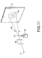
- a goniometer head 61 supports a specimen S , which is to be investigated on its internal crystal structure, etc.
- X-ray emitted and diverging from an X-ray source F 1 is directed to the specimen S by a pinhole collimator 62.
- the specimen S is irradiated with the X-ray.
- diffracted X-ray or scattered X-ray occurs from the specimen S correspondingly to the internal crystal structure of the specimen S .
- the diffracted or scattered X-ray from the specimen S is limited on its cross sectional area by a divergence limiting slit 63 to be incident on an X-ray receiving surface, namely a surface made of storage fluorescent member, of the X-ray image storing member 17.
- an X-ray receiving surface namely a surface made of storage fluorescent member, of the X-ray image storing member 17.
- the X-ray receiving surface is exposed with the X-ray.
- a latent image of energy is formed at a coordinates of the X-ray receiving surface of the X-ray image storing member 17, which corresponds to diffraction angle of the diffracted X-ray, that is, to the internal crystal structure of the specimen S .
- Debye rings 64 are stored as the latent image of energy.
- the X-ray image reader 1 shown in FIG. 1 performs a reading process for the latent image in either the double head mode or the single head mode as described in the following.
- the operator instructs the CPU 41 of the double head mode measurement through the operational input device 56.
- the CPU 41 sets the operation mode of the computer to the double head mode Md.
- the CPU 41 activates the main scan rotary drive 37 as shown in FIG. 1 to rotate the rotary mechanism 4 to thereby rotate the first and second read heads H1 and H2 about the axis line X0.
- Rotation speed at this moment is preliminarily set to a predetermined value and the CPU 41 controls the main scan rotary drive 37 in such a way that the rotation speed is maintained at the predetermined rotation speed.
- the sensor 36 as shown in FIG. 1 outputs the index signal and the EVEN signal such as shown in FIG. 5.
- the index signal is outputted every time when the first and second read heads H1 and H2 rotate in the direction shown by the arrow F by 180°, respectively.
- the EVEN signal is outputted every time when the first read head H1 rotates in the direction F by 360°.
- the laser light generator 27 as shown in FIG. 1 is instructed to start laser light emission.
- a Z axis motor drive pulse signal is supplied to the sub scan drive 38 as shown in FIG. 1 to move the whole X-ray image reader 1 vertically to thereby move the first and second read heads H1 and H2 in a direction shown by an arrow G parallel to the axis line X0.
- Speed of the straight movement of the read heads H1 and H2 is controlled to a constant value V , which is determined by the pulse width of the Z-axis motor drive pulse signal.
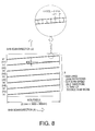
- the first and second read heads H1 and H2 When the first and second read heads H1 and H2 perform the main scan of the X-ray image storing member 17 by rotating in the direction shown by an arrow F , while performing the sub scan by moving straight in the direction shown by an arrow G , the X-ray image storing member 17 is helically scanned by the first and second read heads H1 and H2, which come thereto alternatively as shown by P in FIG. 7.
- the number of scan lines is set to, for example, 3000.
- two scan lines are formed by the first and second read heads H1 and H2 when the rotary mechanism 4 is rotated one time. Therefore, it is possible to form 3000 scan lines by rotating the rotary mechanism 1500 times.
- laser light from the laser light generator 27 as shown in FIG. 1 is reflected by the prism 28 to the laser light input portion 6 of the rotary mechanism 4 and then divided to the first and second read heads H1 and H2 by the beam splitter 18.
- the laser light supplied to the one read head passes therethrough and exposes the X-ray image storing member 17 along the scan lines P shown in FIG. 7.
- the energy is excited by the laser light and emitted externally as light. Then, the light emitted from the X-ray image-storing member 17 is received by one of the first and second read heads H1 and H2.
- the light received by the read head is reflected by the dichroic mirror 26a or 26b in the head portion 7 of the rotary mechanism 4 to the first and second phototubes 16a and 16b of the photo detector 11 and then signals corresponding to the lights are outputted from output terminals of the phototubes.
- the RESET signal is transmitted to the RESET terminal of the frequency divider circuit 51 of the pulse generator circuit 47 as shown in FIG. 4 correspondingly to the index signal outputted every half rotation of the first and second read heads H1 and H2 as shown in FIG. 5, and so single ENC-Z phase pulses and successive ENC-A phase pulses are outputted to the output terminal of the logic circuit 52.
- the ENC-Z phase pulse is generated after a time period t z of the generation of the index signal.
- the ENC-A phase pulse is successively generated in a time period from the generation of the ENC-Z phase pulse to a generation of a next index signal, that is, a time period during which the first read head H1 or the second read head H2 makes a half rotation which corresponds to an angle of 180 degrees.
- the frequency of the ENC-A phase pulse signal is 312.5 KHz, which is the output frequency of the frequency divider 51 shown in FIG. 4, and includes 3000 pulses during the half rotation of the read head corresponding to one scan line as shown in FIG. 6.
- the intensity calculation circuit 48 shown in FIG. 4 reads the output of the phototube 16a or 16b for every pulse of the ENC-A phase pulse signal from the logic circuit 52.
- the read value is stored in a predetermined region of the RAM 43.
- data for 1 pixel corresponding to one pulse of the ENC-A phase pulse signal is sampled.
- the width of 1 pixel corresponds to 0.1 mm as shown in FIG. 7. Since 3000 pulses of the ENC-A phase pulse signal are outputted for 1 scan line, the intensity calculation circuit 48 samples data for 3000 pixels obtained by dividing 1 scan line by 3000.
- the light intensity data of the whole area of the measuring region of the X-ray image storing member 17 is read out as shown in FIG. 7 and the data is stored in a predetermined region of the RAM 43 correspondingly to the coordinates values of the X-ray image storing member 17 in the form of a data table.
- the data table is nothing but the read result of the latent image of energy stored in the X-ray image-storing member 17.
- the data table is displayed on a screen of the display 54 or printed out on a recording sheet such as a printing paper by the printer 53, according to necessity, under control of the CPU 41.
- the reading operation is performed by alternatively using the first and second read heads H1 and H2.
- the reading characteristics of the first read head H1 is not always identical to that of the second read head H2.
- an output level of the phototube 16a or 16b when the X-ray image storing member 17 is read by using the first read head H1 is not always the same as that when the X-ray image storing member 17 is read by using the second read head H2.
- the first read head H1 and the second read head H2 must be strictly arranged with an angular interval of 180 degrees fundamentally, it is practical that the interval may be deviated from 180 degrees due to matching error and/or assembling error of the X-ray image reader 1.
- the CPU 41 shown in FIG. 4 preliminarily acquires a difference in reading characteristics between the first and second read heads H1 and H2 by executing the reading of the same object to be measured as data and stores the latter data in the RAM 43 as correction data.
- the CPU 41 functions as an inter-head intensity correcting means for compensating for error in intensity between the read heads and as an inter-head positional deviation correcting means for compensating for deviation of the angular position between the read heads.
- the operator instructs the CPU 41 of the single head mode measurement through the operational input device 56.
- the CPU 41 sets the operation mode of the computer to the single head mode Ms.
- the CPU 41 activates the main scan rotary drive 37 as shown in FIG. 1 to rotate the rotary mechanism 4 to thereby rotate the first and second read heads H1 and H2 about the axis line X0. Rotation speed at this moment is preliminarily set to the same predetermined value as used in the double head mode.
- the sensor 36 as shown in FIG. 1 With the rotation of the first and second read heads H1 and H2, the sensor 36 as shown in FIG. 1 outputs the index signal and the EVEN signal such as shown in FIG. 5 as in the case of the double head mode.
- the laser light generator 27 as shown in FIG. 1 is instructed to start laser light emission.
- a Z axis motor drive pulse signal is supplied to the sub scan drive 38 as shown in FIG. 1 to move the whole X-ray image reader 1 vertically to thereby move the first and second read heads H1 and H2 in a direction shown by an arrow G parallel to the axis line X0.
- Speed of the straight movement of the read heads H1 and H2 is controlled to a constant value, which is a half of the speed V in the case of the double head mode, by making the pulse width of the Z axis drive pulse a half of that in the case of the double head mode.
- the signal to the laser generator 27 is maintained in ON state as shown in the timing chart shown in FIG. 5 to always generate the laser light during the reading process.
- the laser light is generated in only a time period from the generation of the EVEN signal to a generation of a next index signal, that is, in only a time for which the first read head H1 scans the X-ray image storing member 17, by sending the ON signal to the laser generator 27 for only that time period as shown in the timing chart shown in FIG. 5, such that laser light is not generated during a time period in which the second read head H2 scans the X-ray image storing member 17.
- the reading process with the X-ray image-storing member 17 being irradiated with laser light is performed only when the first read head H1 scans the X-ray image-storing member 17, while the second read head H2 does not perform the reading process during the scan of the X-ray image-storing member 17.
- a tilting angle of the scan line in the single head mode is a half of the tilting angle ⁇ of the scan line in the double head mode as shown in FIG. 7.
- the number of required scans and hence the number of scan lines is set to the same as that in the double head mode, that is, 3000.
- one scan line is formed only by the first read head H1 in one rotation of the rotary mechanism 4 shown in FIG. 1. Therefore, in order to form 3000 scan lines, it is necessary to rotate the rotary mechanism 3000 times, that is, 2 times that in the double head mode.
- laser light from the laser light generator 27 shown in FIG. 1 passes through the first read head H1 and exposes the X-ray image-storing member 17 along the scan line P shown in FIG. 8.
- the energy is excited by the laser light and emitted externally as light.
- the light emitted from the X-ray image-storing member 17 is received by the first read head H1 from which the laser light is emitted.
- the light received by the read head is reflected by the dichroic mirror 26a in the head portion 7 of the rotary mechanism 4 to the first and second phototubes 16a and 16b of the photo detector 11 and signals corresponding to the lights are outputted from output terminals of the phototubes.
- the RESET signal is transmitted to the RESET terminal of the frequency divider circuit 51 of the pulse generator circuit 47 shown in FIG. 4 correspondingly to the EVEN signal outputted every rotation of the first read head H1 as shown in FIG. 5 and so single ENC-Z phase pulses and successive ENC-A phase pulses are outputted to the output terminal of the logic circuit 52.
- the ENC-Z phase pulse is generated after a time t z from the generation of the EVEN signal.
- the ENC-A phase pulse is successively generated in a time period from the generation of the ENC-Z phase pulse to a generation of a next index signal, that is, a time period during which the first read head H1 makes a half rotation corresponding an angle of 180 degrees.
- the frequency of the ENC-A phase pulse signal is 312.5 KHz, which is the output frequency of the frequency divider 51, and includes 3000 pulses during the half rotation of the read head corresponding to one scan line as shown in FIG. 6.
- the intensity calculation circuit 48 shown in FIG. 4 reads the output of the phototube 16a or 16b for every pulse of the ENC-A phase pulse signal from the logic circuit 52.
- the read value is stored in a predetermined region of the RAM 43. In this manner, data for 1 pixel corresponding to one pulse of the ENC-A phase pulse signal is sampled. Since 3000 pulses of the ENC-A phase pulse signal are outputted for 1 scan line, the intensity calculation circuit 48 samples data for 3000 pixels obtained by dividing 1 scan line by 3000.
- the sampling of data for 3000 pixels in one scan line formed by one revolution of the first read head H1 is performed repeatedly, resulting in data for 3000 lines in the sub scan direction is sampled.
- the light intensity data of the whole area of the measuring region of the X-ray image storing member 17 is read out as shown in FIG. 8 and the data is stored in a predetermined region of the RAM 43 correspondingly to the coordinates values of the X-ray image storing member 17 in the form of a data table.
- the reading operation is performed only by the first read head H1, while the data acquisition by the second read head H2 is not performed. Therefore, the problem of error due to the difference in reading characteristics between the first read head H1 and the second read head H2 in the double head mode is solved and it becomes possible to perform a very precise measurement.
- the ON/OFF operation of the laser generator 27 is performed every generation of the EVEN signal and the index signal as shown in FIG. 5.
- laser light having a rated intensity is not generated immediately even when the operation of the laser generator 27 is started in response to the ON signal and a certain time is required before the laser light output is stabilized at the rated intensity.
- This time is realized by the time t z , which is provided between the generation of the EVEN signal and the generation of the ENC-A phase pulse and, in this embodiment, 400 ⁇ S corresponding to 122 pulses, as shown in FIG. 5.
- the single head mode is realized by using only one of the two read heads, for example, the first read head H1, and the generation of laser light from the laser generator 27 is stopped when the other read head, that is, the second read head H2, scans the X-ray image storing member 17.
- the means for making the second read head out of use is not limited to this scheme of stopping the generation of laser light.
- a beam stopper or shutter 59 is provided on the optical path between the beam splitter 18 and the second read head H2 as shown in FIG. 9 to block laser light toward the second read head H2.
- the present invention is applied to the double head type X-ray image reader having two read heads, it is possible to apply the present invention to a multi head type X-ray image reader having three or more read heads.
Landscapes
- Physics & Mathematics (AREA)
- General Physics & Mathematics (AREA)
- Immunology (AREA)
- Pathology (AREA)
- Chemical & Material Sciences (AREA)
- Analytical Chemistry (AREA)
- Biochemistry (AREA)
- General Health & Medical Sciences (AREA)
- Health & Medical Sciences (AREA)
- Life Sciences & Earth Sciences (AREA)
- Facsimile Scanning Arrangements (AREA)
- Radiography Using Non-Light Waves (AREA)
- Analysing Materials By The Use Of Radiation (AREA)
- Conversion Of X-Rays Into Visible Images (AREA)
- Image Input (AREA)
- Apparatus For Radiation Diagnosis (AREA)
Applications Claiming Priority (2)
| Application Number | Priority Date | Filing Date | Title |
|---|---|---|---|
| JP2001284702 | 2001-09-19 | ||
| JP2001284702A JP3925840B2 (ja) | 2001-09-19 | 2001-09-19 | X線画像読取り装置 |
Publications (2)
| Publication Number | Publication Date |
|---|---|
| EP1296181A2 true EP1296181A2 (fr) | 2003-03-26 |
| EP1296181A3 EP1296181A3 (fr) | 2006-07-26 |
Family
ID=19107975
Family Applications (1)
| Application Number | Title | Priority Date | Filing Date |
|---|---|---|---|
| EP02256393A Withdrawn EP1296181A3 (fr) | 2001-09-19 | 2002-09-16 | Appareil de lecture pour image radiographique |
Country Status (3)
| Country | Link |
|---|---|
| US (1) | US6809331B2 (fr) |
| EP (1) | EP1296181A3 (fr) |
| JP (1) | JP3925840B2 (fr) |
Cited By (2)
| Publication number | Priority date | Publication date | Assignee | Title |
|---|---|---|---|---|
| WO2011082738A1 (fr) * | 2009-12-21 | 2011-07-14 | DüRR DENTAL AG | Cassette pour un écran photostimulable, écran photostimulable pour une telle cassette, appareil pour la lecture d'un écran photostimulable, appareil d'examen doté d'une telle cassette et procédé d'enregistrement d'images panographiques |
| KR102571666B1 (ko) * | 2022-11-30 | 2023-08-28 | (주)모아소프트 | 개선된 구조를 갖는 cr 리더장치 |
Families Citing this family (2)
| Publication number | Priority date | Publication date | Assignee | Title |
|---|---|---|---|---|
| JP4073696B2 (ja) * | 2001-09-26 | 2008-04-09 | 富士フイルム株式会社 | 画像情報読取装置 |
| JP2008521020A (ja) * | 2004-10-29 | 2008-06-19 | オレックス コンピューテッド ラジオグラフィー リミテッド | 蓄積性蛍光体シートからの画像読出方法及び装置 |
Citations (2)
| Publication number | Priority date | Publication date | Assignee | Title |
|---|---|---|---|---|
| JPH0619014A (ja) | 1992-07-03 | 1994-01-28 | Rigaku Corp | 潜像読み取り装置 |
| WO1999027409A1 (fr) | 1997-11-20 | 1999-06-03 | Digident Ltd. | Dispositif de balayage |
Family Cites Families (3)
| Publication number | Priority date | Publication date | Assignee | Title |
|---|---|---|---|---|
| JPS59126278A (ja) * | 1983-01-08 | 1984-07-20 | Fuji Photo Film Co Ltd | オ−トラジオグラフイ−における信号処理法 |
| JPS60198532A (ja) * | 1984-03-23 | 1985-10-08 | Fuji Photo Film Co Ltd | 放射線画像情報読取装置 |
| US6700131B2 (en) * | 2000-05-02 | 2004-03-02 | Alara, Inc. | Systems for detecting and compensating for image artifacts while scanning an imagine plate |
-
2001
- 2001-09-19 JP JP2001284702A patent/JP3925840B2/ja not_active Expired - Fee Related
-
2002
- 2002-09-13 US US10/242,449 patent/US6809331B2/en not_active Expired - Fee Related
- 2002-09-16 EP EP02256393A patent/EP1296181A3/fr not_active Withdrawn
Patent Citations (2)
| Publication number | Priority date | Publication date | Assignee | Title |
|---|---|---|---|---|
| JPH0619014A (ja) | 1992-07-03 | 1994-01-28 | Rigaku Corp | 潜像読み取り装置 |
| WO1999027409A1 (fr) | 1997-11-20 | 1999-06-03 | Digident Ltd. | Dispositif de balayage |
Cited By (2)
| Publication number | Priority date | Publication date | Assignee | Title |
|---|---|---|---|---|
| WO2011082738A1 (fr) * | 2009-12-21 | 2011-07-14 | DüRR DENTAL AG | Cassette pour un écran photostimulable, écran photostimulable pour une telle cassette, appareil pour la lecture d'un écran photostimulable, appareil d'examen doté d'une telle cassette et procédé d'enregistrement d'images panographiques |
| KR102571666B1 (ko) * | 2022-11-30 | 2023-08-28 | (주)모아소프트 | 개선된 구조를 갖는 cr 리더장치 |
Also Published As
| Publication number | Publication date |
|---|---|
| EP1296181A3 (fr) | 2006-07-26 |
| US20030053596A1 (en) | 2003-03-20 |
| JP2003091719A (ja) | 2003-03-28 |
| US6809331B2 (en) | 2004-10-26 |
| JP3925840B2 (ja) | 2007-06-06 |
Similar Documents
| Publication | Publication Date | Title |
|---|---|---|
| US6741082B2 (en) | Distance information obtaining apparatus and distance information obtaining method | |
| JP2580933B2 (ja) | ジッター量測定手段を有した光走査装置 | |
| KR0133076B1 (ko) | 기록 헤드 제어기 | |
| US5283681A (en) | Scanning optical equipment | |
| US6809331B2 (en) | X-ray image reader | |
| US20040165236A1 (en) | Scanner having a light beam incident position adjusting device | |
| US5307198A (en) | Scanner with combined predictive and diffractive feedback control of beam position | |
| JPH08110488A (ja) | 光走査装置 | |
| JP2003075761A (ja) | 光走査装置 | |
| JP4014129B2 (ja) | X線画像読取り装置 | |
| US5302972A (en) | Method of setting density for image recording apparatus | |
| JP2940962B2 (ja) | ポリゴンスキャナのジッタ計測装置 | |
| JPH0446257Y2 (fr) | ||
| JP3478454B2 (ja) | 画像記録装置 | |
| JPH07281112A (ja) | 画像記録装置 | |
| JPH1058740A (ja) | マルチビーム走査型画像形成装置・走査線ピッチ検出方法・走査線ピッチ検出装置 | |
| KR20030097119A (ko) | 갈바노 미터의 회전자 위치 측정 시스템 | |
| JPH0690111B2 (ja) | 動的面出入り測定装置 | |
| JPH10149427A (ja) | 光学走査装置及び光学情報読取装置並びに光学情報記録装置 | |
| JP2000258339A (ja) | 複屈折測定装置 | |
| JP2002286417A (ja) | 走査ビーム測定評価装置及び画像形成装置 | |
| JPS5915221A (ja) | 光走査装置 | |
| JPH07198347A (ja) | プランジヤ測定装置 | |
| JPH09263002A (ja) | 電子写真装置 | |
| JPH0782533B2 (ja) | 形状測定装置 |
Legal Events
| Date | Code | Title | Description |
|---|---|---|---|
| PUAI | Public reference made under article 153(3) epc to a published international application that has entered the european phase |
Free format text: ORIGINAL CODE: 0009012 |
|
| AK | Designated contracting states |
Kind code of ref document: A2 Designated state(s): AT BE BG CH CY CZ DE DK EE ES FI FR GB GR IE IT LI LU MC NL PT SE SK TR |
|
| AX | Request for extension of the european patent |
Extension state: AL LT LV MK RO SI |
|
| PUAL | Search report despatched |
Free format text: ORIGINAL CODE: 0009013 |
|
| RIC1 | Information provided on ipc code assigned before grant |
Ipc: H04N 1/06 20060101ALI20060615BHEP Ipc: H04N 1/00 20060101ALI20060615BHEP Ipc: G01T 1/29 20060101AFI20060615BHEP |
|
| AK | Designated contracting states |
Kind code of ref document: A3 Designated state(s): AT BE BG CH CY CZ DE DK EE ES FI FR GB GR IE IT LI LU MC NL PT SE SK TR |
|
| AX | Request for extension of the european patent |
Extension state: AL LT LV MK RO SI |
|
| 17P | Request for examination filed |
Effective date: 20061019 |
|
| AKX | Designation fees paid |
Designated state(s): DE |
|
| 17Q | First examination report despatched |
Effective date: 20100202 |
|
| STAA | Information on the status of an ep patent application or granted ep patent |
Free format text: STATUS: THE APPLICATION IS DEEMED TO BE WITHDRAWN |
|
| 18D | Application deemed to be withdrawn |
Effective date: 20170401 |