EP1295753A1 - Gelenkbeschlag für einen Kraftfahrzeugsitz mit vorkippbarer Rückenlehne - Google Patents
Gelenkbeschlag für einen Kraftfahrzeugsitz mit vorkippbarer Rückenlehne Download PDFInfo
- Publication number
- EP1295753A1 EP1295753A1 EP02013219A EP02013219A EP1295753A1 EP 1295753 A1 EP1295753 A1 EP 1295753A1 EP 02013219 A EP02013219 A EP 02013219A EP 02013219 A EP02013219 A EP 02013219A EP 1295753 A1 EP1295753 A1 EP 1295753A1
- Authority
- EP
- European Patent Office
- Prior art keywords
- locking
- cam
- fitting
- articulated
- flank
- Prior art date
- Legal status (The legal status is an assumption and is not a legal conclusion. Google has not performed a legal analysis and makes no representation as to the accuracy of the status listed.)
- Granted
Links
- 230000000903 blocking effect Effects 0.000 claims description 24
- 230000033001 locomotion Effects 0.000 claims description 11
- 230000036316 preload Effects 0.000 claims description 4
- 230000009471 action Effects 0.000 description 3
- 238000011161 development Methods 0.000 description 3
- 230000008901 benefit Effects 0.000 description 2
- 230000005540 biological transmission Effects 0.000 description 2
- 230000001133 acceleration Effects 0.000 description 1
- 238000013459 approach Methods 0.000 description 1
- 238000010276 construction Methods 0.000 description 1
- 230000000694 effects Effects 0.000 description 1
- 230000006872 improvement Effects 0.000 description 1
- 238000004519 manufacturing process Methods 0.000 description 1
- 239000000463 material Substances 0.000 description 1
- 230000007246 mechanism Effects 0.000 description 1
- 239000002184 metal Substances 0.000 description 1
- 238000000034 method Methods 0.000 description 1
- 230000008569 process Effects 0.000 description 1
- 238000012549 training Methods 0.000 description 1
Images


Classifications
-
- B—PERFORMING OPERATIONS; TRANSPORTING
- B60—VEHICLES IN GENERAL
- B60N—SEATS SPECIALLY ADAPTED FOR VEHICLES; VEHICLE PASSENGER ACCOMMODATION NOT OTHERWISE PROVIDED FOR
- B60N2/00—Seats specially adapted for vehicles; Arrangement or mounting of seats in vehicles
- B60N2/02—Seats specially adapted for vehicles; Arrangement or mounting of seats in vehicles the seat or part thereof being movable, e.g. adjustable
- B60N2/20—Seats specially adapted for vehicles; Arrangement or mounting of seats in vehicles the seat or part thereof being movable, e.g. adjustable the back-rest being tiltable, e.g. to permit easy access
Definitions
- the invention relates to a joint fitting for a motor vehicle seat is intended with a tiltable backrest and the first one Fitting part, a second fitting part and a swivel joint, about that these two fittings are pivotally connected.
- Such motor vehicle seats also have a fitting that enables an inclination adjustment of the backrest relative to the seat support.
- the adjustment of this fitting is relatively time consuming.
- With the joint fitting of the type mentioned is a quick adjustment around a larger angular range, for example 90 °.
- the known hinge fitting is free of play in that the hook with the bolt comes into contact along a hook surface, which increases with increasing Swiveling the hook around the bolt the bolt more and more to the swivel axis of the hook.
- the hook is normally in its locked position.
- the hook is assigned an elastic means that preloads it in the locked position.
- a traction device is provided which engages the hook and enables the hook from its locked position and against the action of the elastic By swinging out.
- the traction device ends in a handle, which is usually in the upper area of the backrest, on the side of the Backrest. If this handle is actuated, the hook swings free and a quick adjustment of the backrest is possible.
- the locking cam forms the necessary one Stop that the when the backrest is folded back Backward movement limited.
- a separate stop as with the joint fitting according to the state of the art, is not necessary.
- the Locking cam which has a similar function as the hook in the joint fitting according to the state of the art, not only causes the fixation in one swivel direction, but in both possible swivel directions the backrest.
- the swivel axis i.e. the cam axis
- the first locking edge can be in the immediate vicinity of the cam axis, so that the storage of the locking cam can be simple can.
- the joint fitting can be made free of play with simple means. Compared to the hinge fitting according to the prior art are fewer Parts needed. The blocking takes place with greater precision. This is also the transmission of the joint position of the joint fitting on one side of the seat simplified and done on the hinge fitting of the other seat side more accurate.
- the hook is that pivoting locking means.
- the swivel axis becomes this Locking means pulled towards the restricted area.
- this is accurate vice versa.
- the free end of the locking cam presses this Swivel away. Because in the immediate vicinity of the swivel joint but a support in the form of the end region there, namely the first End range, and the first locking edge is not the pivot axis determining the locking position, rather the fit of the locking cam and the bulky bay.
- a circle around the hinge axis as the center and through the cam axis cuts the first blocking edge, but remains outside the second Blocking flank.
- the locking cam remains outside the range of motion the second locking flank and overall the locking bay when the backrest is tipped forward.
- the first strikes End area on the first locking edge and thereby forms the described Stop when moving back.
- an actuator is provided. This but now acts on the locking cam.
- the locking cam is usually located in the locked position. By operating the operating device it is pivoted from the locked position into the release position. So that is the backrest can be tilted forward quickly.
- a torsion spring is arranged on the locking cam, which preloads it elastically in one direction of rotation, the opposite is the direction of rotation when folding the backrest forward. This torsion spring therefore always loads the locking cam in relation to the first fitting part the locked position and maintains it.
- the backrest tilted at the front the first contact between the first restricted area and the first blocking edge at a point of the first end region instead, which is positioned opposite the cam axis so that a swiveling Torque is reached. So the first contact that the second end region is moved towards the second blocking edge.
- the first blocking edge on a section of a straight line that runs through the hinge axis goes. This makes a precise stop when the backrest is swung back reached.
- the actuating device has a control part, which is articulated on the second fitting part.
- a traction device is provided which is designed in particular as a Bowden cable, and pivoting the Control part from its rest position to a release position.
- the control section has a release arm that turns the control cam when the traction mechanism is actuated moves from the locked position to the release position.
- the locking cam is actuated.
- it is possible to use the locking cam can also be operated directly, but has to be operated via the control section the advantage that the traction device can attack a part that joins with the same fitting as the handle of the traction device. So it is not necessary to arrange the traction device so that by the pivoting movement the backrest is not subjected to any tension on the traction device.
- control part has a retaining lug, which is in the rest position of the control part engages behind a blocking edge of the locking cam. In this way, the locking cam is mechanically blocked. He can too with acceleration forces that attack the locking cam, not from the Locked position can be pressed.
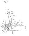
- a motor vehicle seat can be seen from the figures, which has a tiltable seat Backrest 20 is equipped. It still has a seat support 22.
- the latter is shown schematically, it is about a known per se Underframe (not shown) with an underbody of a motor vehicle (not shown) connected.
- Backrest 20 and seat support 22 are connected to one another via an articulated fitting connected.
- This has a first fitting part 24, which is essentially is plate-shaped and in two attachment points with the Seat support 22 is connected, and a second fitting part 26, which is to the backrest heard it is with a back support (not shown) connected.
- These two fitting parts 24, 26 are by means of a swivel joint pivotally connected to each other about a hinge axis 28.
- a locking cam 30 is pivoted about a cam axis 32. It has a first end region 34 which is in the immediate vicinity Located near the cam axis 32 and still one of the first End region 34 opposite second end region 36.
- a locking bay in the vicinity of the locking cam 30 38 trained.
- This essentially consists of a first blocking edge 40, one of these opposite second blocking edge 42 and one these locking flanks 40, 42 connecting base 44.
- the locking bay 38 is formally adapted to the locking cam 30 and can this record, as shown in Figure 1 in particular. This includes, among other things the distance between the blocking surfaces 40, 42 the distance between the two end regions 34, 36 adjusted.
- the second end region 36 and the second blocking edge 42 are formally coordinated so that with increasing Pivotal movement of the locking cam 30 about its cam axis 32 in the Blocking position an increasing contact between the second end region 36 and the second blocking edge 42 occurs.
- the locking cam 30 is in the locking position shown by a torsion spring 36 preloaded elastically. Furthermore, it becomes positive in the locked position will be discussed in the following.
- locking cams 30 and locking bay 38 seen from a front edge of the seat behind the hinge axis 28, they are also at about the same height as this. It is possible the arrangement from locking cams 30 and locking bay 38 also in a different angular position to be arranged to the hinge axis 28 as shown.
- the second fitting part 26 is also plate-shaped.
- the locking cam 30 is preferably made of sheet metal of the same thickness as the second fitting part 26 manufactured.
- first fitting part 24 there are second fitting parts 26 and locking cams 30 on the same side of the first fitting part 20.
- Locking cam 30 On the main surface facing away from the first fitting part 24 Locking cam 30, a plate-shaped security piece is attached. In the pivoting direction of the locking cam 30 in the locking position shown in Figure 1 it is still in front of the corresponding edge of the locking cam 30, therefore overlaps the locking cam 30.
- the security piece 48 also forms one at the free end of the locking cam 30 protruding blocking edge 50 out, this will be discussed later.
- a control part 50 is located in the immediate vicinity of the locking cam 30 an actuator. It is on the other fitting part, namely on the second fitting part 26, arranged as the locking cam 30. It is over a control part axis 52 is pivotally attached to the second fitting part 26. A pivot spring 54 preloads it elastically so that it is against a stop 56 is pressed.
- the control part 50 is essentially three-armed.
- the three arms are in the essentially T-shaped to each other.
- a first, downward arm is connected with a traction device, which is listed here as Bowden cable 58. It ends in the upper area of the backrest 20, laterally, in a handle 60, which is designed for example as a rocker or as a pivot lever. she is designed so that tension is exerted on the soul of the Bowden cable can.
- the handle 60 is located under the action of the pivot spring usually at rest.
- a release arm 62 is opposite the arm described. It has a rounded one Contact area in the figure 1 at a distance from the security piece 48 of the locking cam 30 is.
- This security piece 48 is in the same level as the control part 50, namely still above the second fitting part 26. If train is exerted on Bowden cable 58, the approaches Release arm 62 against the action of the pivot spring 54 the security piece 48.
- the locking cam 30 becomes 32 about its cam axis pivoted clockwise outwards, as shown in Figure 2.
- the backrest 20 can now be tilted forward about the hinge axis 28 in the position shown in Figure 3. Control part 50 remains during this tilting movement and locking cam 30 in contact so that the locking cam 30 is not freely under the effect of its torsion spring 46 can pivot counterclockwise.
- a third arm of the control part 50 is essentially hook-shaped and engages behind the stop in the blocking position shown in FIG. 1 56. This ensures the locking position is mechanically positive.
- the handle 60 on the backrest only has to be actuated as long as until, starting from the state according to FIG. 1, the state according to FIG. 2 is reached and the backrest 20 is forward by a certain angle was pivoted, but without already reaching the position shown in Figure 3.
- a short pre-tilt movement is enough to release the handle 60 of the locking cam 30 does not return to the locking bay 38 independently can come up with.
- the locking cam 30 is located in its locking bay 38.
- the locking cam 30 slips on the control part 50 and partly also on the free narrow surface of the second Fitting part 26 along until the first end region 34 to the first locking edge 40 strikes. This limits the return movement.
- the cam axis 32 is at the same distance from the hinge axis 28 as that Middle of the first blocking edge.
- the second blocking edge 42 has one significantly shorter distance from the hinge axis 28, the same applies to the base 44 and on the other side of the second blocking edge 42 for the subsequent ones Areas of the second fitting part 26. This hinders the Locking cams 30 do not tilt the backrest 20.
Landscapes
- Engineering & Computer Science (AREA)
- Aviation & Aerospace Engineering (AREA)
- Transportation (AREA)
- Mechanical Engineering (AREA)
- Chairs For Special Purposes, Such As Reclining Chairs (AREA)
- Seats For Vehicles (AREA)
Abstract
Description
- einen Sperrnocken, der am ersten Beschlagteil um eine Nockenachse schwenkbar angelenkt ist, und der einen ersten, in Nähe der Nockenachse befindlichen Endbereich und einen diesem ersten Endbereich gegenüberliegenden, zweiten Endbereich hat,
- eine Sperrbucht, die am zweiten Beschlagteil ausgebildet ist, die eine erste Sperrflanke und eine dieser gegenüberliegende Sperrflanke aufweist, wobei der Abstand dieser Sperrflanken dem Abstand der beiden Endbereiche angepasst ist und diese Sperrflanken so angeordnet sind, dass ein Kreisbogen um die Gelenkachse als Zentrum, der durch die Nockenachse verläuft, die erste Sperrflanke schneidet und außerhalb der zweiten Sperrflanke verläuft und
- eine Betätigungsvorrichtung, die am Sperrnocken im Abstand von der Nockenachse angreift, so dass der Sperrnocken aus einer Sperrstellung in eine Freigabestellung betätigt werden kann,
- wobei in der Sperrstellung der erste Endbereich des Sperrnockens an der ersten Sperrflanke und der zweite Endbereich des Sperrnockens an der zweiten Sperrflanke anliegen.
Claims (10)
- Gelenkbeschlag, der für einen Kraftfahrzeugsitz mit vorkippbarer Rükkenlehne (20) bestimmt ist und der ein erstes Beschlagteil (24), ein zweites Beschlagteil (26) und ein Schwenkgelenk aufweist, über das diese beiden Beschlagteile schwenkbar miteinander verbunden sind, dieser Gelenkbeschlag weist weiterhin auf,einen Sperrnocken (30), der am ersten Beschlagteil (24) um eine Nokkenachse (32) schwenkbar angelenkt ist, und der einen ersten, in Nähe der Nockenachse (32) befindlichen Endbereich (34) und einen diesem ersten Endbereich (34) gegenüberliegenden, zweiten Endbereich (36) hat,eine Sperrbucht (38), die am zweiten Beschlagteil (26) ausgebildet ist, die eine erste Sperrflanke (40) und eine dieser gegenüberliegende Sperrflanke (42) aufweist, wobei der Abstand dieser Sperrflanken (42) dem Abstand der beiden Endbereiche angepasst ist und diese Sperrflanken (40, 42) so angeordnet sind, dass ein Kreisbogen um die Gelenkachse (28) als Zentrum, der durch die Nockenachse (32) verläuft, die erste Sperrflanke (40) schneidet und außerhalb der zweiten Sperrflanke (42) verläuft undeine Betätigungsvorrichtung, die am Sperrnocken (30) im Abstand von der Nockenachse (32) angreift, so dass der Sperrnocken (30) aus einer Sperrstellung in eine Freigabestellung betätigt werden kann,wobei in der Sperrstellung der erste Endbereich (34) des Sperrnockens (30) an der ersten Sperrflanke (40) und der zweite Endbereich (36) des Sperrnockens (30) an der zweiten Sperrflanke (42) anliegen.
- Gelenkbeschlag nach Anspruch 1, dadurch gekennzeichnet, dass zwischen Sperrnocken (3) und erstem Beschlagteil (24) eine Drehfeder (46) angeordnet ist, die den Sperrnocken (30) relativ zum ersten Beschlagteil (24) in einer Drehrichtung vorbelastet, die gegensätzlich ist zur Drehrichtung beim Vorklappen der Rückenlehne (20).
- Gelenkbeschlag nach Anspruch 1, dadurch gekennzeichnet, dass die erste Sperrflanke (40) entlang einer Geraden verläuft, die durch die Nockenachse (32) geht.
- Gelenkbeschlag nach Anspruch 1, dadurch gekennzeichnet, dass die Betätigungsvorrichtung ein Steuerteil (50) aufweist, das am zweiten Beschlagteil (26) angelenkt ist, das mit einem Zugmittel, insbesondere Bowdenzug (58), verbunden ist, und das einen Lösearm (62) hat, der bei Betätigung des Zugmittels den Sperrnocken (30) aus der Sperrstellung in eine Freigabestellung drückt.
- Gelenkbeschlag nach Anspruch 4, dadurch gekennzeichnet, dass das Steuerteil (50) weiterhin eine Haltenase aufweist, die in Ruhestellung des Steuerteils (50) hinter eine Blockierflanke des Sperrnockens (30) greift.
- Gelenkbeschlag nach Anspruch 1, dadurch gekennzeichnet, dass der Sperrnocken (30) mindestens ein Sicherheitsstück (48) aufweist, das sich in Sperrstellung des Sperrnockens (30) seitlich neben dem zweiten Beschlagteil (26) befindet.
- Gelenkbeschlag nach Anspruch 5, dadurch gekennzeichnet, dass in Sperrstellung des Sperrnockens (30) sich der Sperrnocken (30) zwischen einem Sicherheitsstück (48) und dem ersten Beschlagteil (24) befindet.
- Gelenkbeschlag nach Anspruch 1, dadurch gekennzeichnet, dass das erste Beschlagteil (24) mit einem Sitzträger (22) verbunden ist und dass das zweite mit einem Rückenlehnenträger (20) verbunden ist.
- Gelenkbeschlag nach Anspruch 1, dadurch gekennzeichnet, dass der Kraftfahrzeugsitz zwei Sitzseiten hat, und dass an jeder Sitzseite jeweils ein Gelenkbeschlag vorgesehen ist, wobei die beiden Gelenkbeschläge durch eine Mitnehmereinrichtung miteinander bewegungsverbunden sind.
- Gelenkbeschlag nach Anspruch 4, dadurch gekennzeichnet, dass dem Steuerteil (50) eine Schwenkfeder (54) zugeordnet ist, die das Steuerteil (50) in eine Position elastisch vorbelastet, in der es sich außerhalb der Sperrbucht (38) befindet.
Applications Claiming Priority (2)
| Application Number | Priority Date | Filing Date | Title |
|---|---|---|---|
| DE10146300A DE10146300A1 (de) | 2001-09-19 | 2001-09-19 | Gelenkbeschlag für einen Kraftfahrzeugsitz mit vorkippbarer Rückenlehne |
| DE10146300 | 2001-09-19 |
Publications (2)
| Publication Number | Publication Date |
|---|---|
| EP1295753A1 true EP1295753A1 (de) | 2003-03-26 |
| EP1295753B1 EP1295753B1 (de) | 2006-07-26 |
Family
ID=7699630
Family Applications (1)
| Application Number | Title | Priority Date | Filing Date |
|---|---|---|---|
| EP02013219A Expired - Lifetime EP1295753B1 (de) | 2001-09-19 | 2002-06-15 | Gelenkbeschlag für einen Kraftfahrzeugsitz mit vorkippbarer Rückenlehne |
Country Status (3)
| Country | Link |
|---|---|
| US (1) | US6736460B2 (de) |
| EP (1) | EP1295753B1 (de) |
| DE (2) | DE10146300A1 (de) |
Cited By (2)
| Publication number | Priority date | Publication date | Assignee | Title |
|---|---|---|---|---|
| WO2007082759A1 (de) * | 2006-01-19 | 2007-07-26 | Johnson Controls Gmbh | Fahrzeugsitz mit höhenverstellbereich und absenkposition |
| CN102239065B (zh) * | 2008-10-23 | 2015-04-29 | 约翰逊控制器有限责任公司 | 尤其用于调整配合件并且尤其用于车辆座椅的锁定设备以及车辆座椅 |
Families Citing this family (10)
| Publication number | Priority date | Publication date | Assignee | Title |
|---|---|---|---|---|
| DE10143721B4 (de) * | 2001-08-31 | 2005-09-29 | Brose Fahrzeugteile Gmbh & Co. Kg, Coburg | Kraftfahrzeugsitz |
| DE10244290B4 (de) * | 2002-09-23 | 2009-01-29 | C. Rob. Hammerstein Gmbh & Co. Kg | Kraftfahrzeugsitz mit einem Rückenlehnengelenk |
| DE10351157B3 (de) * | 2003-11-03 | 2005-06-09 | Faurecia Autositze Gmbh & Co. Kg | Kraftfahrzeugsitz |
| JP4776895B2 (ja) * | 2004-07-05 | 2011-09-21 | 株式会社デルタツーリング | シート構造 |
| DE102008005573A1 (de) | 2007-01-23 | 2008-07-24 | C. Rob. Hammerstein Gmbh & Co. Kg | Verfahren zur Betätigung eines Kraftfahrzeugssitzes und dafür geeigneter Kraftfahrzeugsitz |
| DE102007025318B3 (de) * | 2007-05-31 | 2009-01-22 | Lear Corp., Southfield | Fahrzeugsitz |
| DE102009027464A1 (de) * | 2009-07-03 | 2011-01-05 | C. Rob. Hammerstein Gmbh & Co. Kg | Sitzgestell eines Kraftfahrzeugsitzes |
| DE102013225698B4 (de) * | 2013-10-16 | 2015-12-03 | Johnson Controls Components Gmbh & Co. Kg | Easy-Entry-System und Fahrzeugsitz mit einem integrierten Easy-Entry-System |
| US9586503B1 (en) * | 2015-08-28 | 2017-03-07 | Faurecia Automotive Seating Llc | Vehicle seat and torsion bar |
| JP7361676B2 (ja) * | 2020-11-30 | 2023-10-16 | コイト電工株式会社 | 座席装置 |
Citations (5)
| Publication number | Priority date | Publication date | Assignee | Title |
|---|---|---|---|---|
| DE2829701A1 (de) * | 1978-07-06 | 1980-01-17 | Hammerstein Gmbh C Rob | Betaetigungsvorrichtung fuer die sperrklinke eines klappbaren fahrzeugsitzes |
| US4269446A (en) * | 1978-03-29 | 1981-05-26 | Bayerische Motoren Werke Aktiengesellschaft | Displaceable seat for automotive vehicles |
| DE4439644A1 (de) * | 1993-12-17 | 1995-06-22 | Keiper Recaro Gmbh Co | Verriegelungssystem für Gelenkbeschläge von Fahrzeugsitzen, insbesondere für Taumelbeschläge |
| US6030042A (en) * | 1997-06-16 | 2000-02-29 | Bauer; Heinz | Motor vehicle seat with a back rest, which can be tilted forward and a seat carrier, which can be tilted forward |
| EP1034972A2 (de) * | 1999-03-08 | 2000-09-13 | DaimlerChrysler AG | Betätigungsanordnung für einen Fahrzeugsitz |
Family Cites Families (16)
| Publication number | Priority date | Publication date | Assignee | Title |
|---|---|---|---|---|
| US4869541A (en) * | 1988-12-27 | 1989-09-26 | Lear Siegler Seating Corporation | Forwardly pivotal seat assembly |
| US5547254A (en) * | 1992-09-30 | 1996-08-20 | Aisin Seiki Kabushiki Kaisha | Pawl and ratchet type seat tilt control apparatus |
| US5466048A (en) * | 1994-06-16 | 1995-11-14 | Lear Seating Corporation | Backrest release mechanism |
| FR2732281B1 (fr) * | 1995-03-30 | 1997-06-13 | Faure Bertrand Equipements Sa | Siege de vehicule comportant un dossier pivotant monte au moyen d'un dispositif apte a supporter des couples eleves |
| US5577805A (en) * | 1995-10-10 | 1996-11-26 | General Motors Corporation | Van-type vehicle seat |
| US5810444A (en) * | 1995-12-14 | 1998-09-22 | Trw Vehicle Safety Systems Inc. | Seat latch blockout mechanism |
| DE19644087B4 (de) * | 1996-10-31 | 2008-10-16 | C. Rob. Hammerstein Gmbh & Co. Kg | Lehnenbeschlag für einen Kraftfahrzeugsitz |
| BR9713997A (pt) * | 1996-12-09 | 2000-02-29 | Atoma Int Inc | Assento de veìculo |
| US6076890A (en) * | 1997-08-08 | 2000-06-20 | Ikeda Bussan Co., Ltd. | Seat for vehicle |
| JP3532855B2 (ja) * | 1998-01-28 | 2004-05-31 | バートランド・フォーレ・コンポーネンツ・リミテッド | 多機能車両シート用回転リクライナー制御機構 |
| DE19910085C1 (de) * | 1999-03-08 | 2000-10-12 | Daimler Chrysler Ag | Fahrzeugsitz |
| FR2799420B1 (fr) * | 1999-10-08 | 2002-01-04 | Faure Bertrand Equipements Sa | Siege de vehicule |
| FR2822419B1 (fr) * | 2000-12-29 | 2003-07-04 | Faurecia Sieges Automobile | Siege de vehicule equipe d'un mecanisme d'articulation |
| FR2820696B1 (fr) * | 2001-02-15 | 2003-08-08 | Faurecia Sieges Automobile | Siege de vehicule dote d'un dossier rabattable |
| DE10116160A1 (de) * | 2001-03-31 | 2002-10-10 | Keiper Gmbh & Co | Beschlag für einen Fahrzeugsitz |
| FR2830804B1 (fr) * | 2001-10-15 | 2004-01-16 | Faurecia Sieges Automobile | Siege de vehicule comportant un dossier rabattable vers l'avant |
-
2001
- 2001-09-19 DE DE10146300A patent/DE10146300A1/de not_active Withdrawn
-
2002
- 2002-06-15 DE DE50207612T patent/DE50207612D1/de not_active Expired - Lifetime
- 2002-06-15 EP EP02013219A patent/EP1295753B1/de not_active Expired - Lifetime
- 2002-08-16 US US10/222,526 patent/US6736460B2/en not_active Expired - Lifetime
Patent Citations (5)
| Publication number | Priority date | Publication date | Assignee | Title |
|---|---|---|---|---|
| US4269446A (en) * | 1978-03-29 | 1981-05-26 | Bayerische Motoren Werke Aktiengesellschaft | Displaceable seat for automotive vehicles |
| DE2829701A1 (de) * | 1978-07-06 | 1980-01-17 | Hammerstein Gmbh C Rob | Betaetigungsvorrichtung fuer die sperrklinke eines klappbaren fahrzeugsitzes |
| DE4439644A1 (de) * | 1993-12-17 | 1995-06-22 | Keiper Recaro Gmbh Co | Verriegelungssystem für Gelenkbeschläge von Fahrzeugsitzen, insbesondere für Taumelbeschläge |
| US6030042A (en) * | 1997-06-16 | 2000-02-29 | Bauer; Heinz | Motor vehicle seat with a back rest, which can be tilted forward and a seat carrier, which can be tilted forward |
| EP1034972A2 (de) * | 1999-03-08 | 2000-09-13 | DaimlerChrysler AG | Betätigungsanordnung für einen Fahrzeugsitz |
Cited By (3)
| Publication number | Priority date | Publication date | Assignee | Title |
|---|---|---|---|---|
| WO2007082759A1 (de) * | 2006-01-19 | 2007-07-26 | Johnson Controls Gmbh | Fahrzeugsitz mit höhenverstellbereich und absenkposition |
| DE102006002823B4 (de) * | 2006-01-19 | 2014-09-11 | Johnson Controls Gmbh | Fahrzeugsitz mit Höhenverstellbereich und Absenkposition |
| CN102239065B (zh) * | 2008-10-23 | 2015-04-29 | 约翰逊控制器有限责任公司 | 尤其用于调整配合件并且尤其用于车辆座椅的锁定设备以及车辆座椅 |
Also Published As
| Publication number | Publication date |
|---|---|
| EP1295753B1 (de) | 2006-07-26 |
| US6736460B2 (en) | 2004-05-18 |
| DE10146300A1 (de) | 2003-04-03 |
| US20030052523A1 (en) | 2003-03-20 |
| DE50207612D1 (de) | 2006-09-07 |
Similar Documents
| Publication | Publication Date | Title |
|---|---|---|
| DE2708423C2 (de) | Durch Nachvorneschwenken seiner Rückenlehne in eine Einstiegstellung überführbarer, längsverstellbarer Fahrzeugsitz | |
| EP1359051B1 (de) | Lehnengelenkbeschlag für einen Kraftfahrzeugsitz | |
| DE4012860C2 (de) | Freischwenkeinrichtung für die Rückenlehne eines Fahrzeugsitzes, insbesondere Kraftfahrzeugsitzes | |
| DE102007025327B4 (de) | Fahrzeugsitzanordnung | |
| DE3616164C2 (de) | ||
| DE10151470A1 (de) | Gelenkmechanismus für einen Fahrzeugsitz und mit einem solchen Mechanismus ausgestatteter Sitz | |
| EP0555627B1 (de) | Schwenkmechanismus für die Lenkradanordnung eines Fahrzeuges | |
| WO2016001096A1 (de) | Lehnenversteller für einen sitz und fahrzeugsitz | |
| DE4119418C1 (de) | ||
| DE4301811B4 (de) | Rückenlehnengelenk für einen Fahrzeugsitz mit einem Sitzträger und einer an diesem angelenkten Rückenlehne | |
| EP1295753A1 (de) | Gelenkbeschlag für einen Kraftfahrzeugsitz mit vorkippbarer Rückenlehne | |
| DE69127909T2 (de) | Schiebe-Hebe-Dach-Vorrichtung für Kraftfahrzeug | |
| DE202008008312U1 (de) | Drehbeschlag und mit einem Drehbeschlag ausgestatteter Fahrzeugsitz | |
| EP0602361B1 (de) | Rückenlehnengelenk für einen Fahrzeugsitz | |
| DE2248996A1 (de) | Sitz mit verstellbarer rueckenlehne | |
| EP3694744A1 (de) | Fahrzeugsitz mit einem easy-entry-mechanismus | |
| EP3691958A1 (de) | Kippvorrichtung für das fahrerhaus eines lastkraftwagens | |
| DE102010003639A1 (de) | Motorische Stellvorrichtung eines Kraftfahrzeugsitzes mit einem Getriebemotor und einem Stellgetriebe | |
| DE4446741B4 (de) | Betätigungseinrichtung | |
| DE102010050739B4 (de) | Gangschaltmechanismus mit einem einklappbaren Gangschalthebel | |
| EP1033279B1 (de) | Beschlag für einen Fahrzeugsitz | |
| DE19527750C2 (de) | Fahrzeugsitz | |
| EP1149974A1 (de) | Feststellvorrichtung | |
| DE2940141C2 (de) | Einrichtung zur Rückenlehnenverstellung | |
| DE4402978C2 (de) | Rücksitzlehne für Kraftfahrzeuge |
Legal Events
| Date | Code | Title | Description |
|---|---|---|---|
| PUAI | Public reference made under article 153(3) epc to a published international application that has entered the european phase |
Free format text: ORIGINAL CODE: 0009012 |
|
| AK | Designated contracting states |
Kind code of ref document: A1 Designated state(s): AT BE CH CY DE DK ES FI FR GB GR IE IT LI LU MC NL PT SE TR |
|
| AX | Request for extension of the european patent |
Extension state: AL LT LV MK RO SI |
|
| 17P | Request for examination filed |
Effective date: 20030926 |
|
| AKX | Designation fees paid |
Designated state(s): DE FR IT |
|
| GRAP | Despatch of communication of intention to grant a patent |
Free format text: ORIGINAL CODE: EPIDOSNIGR1 |
|
| GRAS | Grant fee paid |
Free format text: ORIGINAL CODE: EPIDOSNIGR3 |
|
| GRAA | (expected) grant |
Free format text: ORIGINAL CODE: 0009210 |
|
| AK | Designated contracting states |
Kind code of ref document: B1 Designated state(s): DE FR IT |
|
| PG25 | Lapsed in a contracting state [announced via postgrant information from national office to epo] |
Ref country code: IT Free format text: LAPSE BECAUSE OF FAILURE TO SUBMIT A TRANSLATION OF THE DESCRIPTION OR TO PAY THE FEE WITHIN THE PRESCRIBED TIME-LIMIT;WARNING: LAPSES OF ITALIAN PATENTS WITH EFFECTIVE DATE BEFORE 2007 MAY HAVE OCCURRED AT ANY TIME BEFORE 2007. THE CORRECT EFFECTIVE DATE MAY BE DIFFERENT FROM THE ONE RECORDED. Effective date: 20060726 |
|
| REF | Corresponds to: |
Ref document number: 50207612 Country of ref document: DE Date of ref document: 20060907 Kind code of ref document: P |
|
| ET | Fr: translation filed | ||
| PLBE | No opposition filed within time limit |
Free format text: ORIGINAL CODE: 0009261 |
|
| STAA | Information on the status of an ep patent application or granted ep patent |
Free format text: STATUS: NO OPPOSITION FILED WITHIN TIME LIMIT |
|
| 26N | No opposition filed |
Effective date: 20070427 |
|
| REG | Reference to a national code |
Ref country code: DE Ref legal event code: R082 Ref document number: 50207612 Country of ref document: DE Representative=s name: PATENTANWAELTE BAUER VORBERG KAYSER PARTNERSCH, DE |
|
| REG | Reference to a national code |
Ref country code: DE Ref legal event code: R082 Ref document number: 50207612 Country of ref document: DE Representative=s name: PATENTANWAELTE BAUER VORBERG KAYSER PARTNERSCH, DE Effective date: 20141016 Ref country code: DE Ref legal event code: R081 Ref document number: 50207612 Country of ref document: DE Owner name: JOHNSON CONTROLS METALS AND MECHANISMS GMBH & , DE Free format text: FORMER OWNER: C. ROB. HAMMERSTEIN GMBH & CO. KG, 42699 SOLINGEN, DE Effective date: 20141016 |
|
| REG | Reference to a national code |
Ref country code: FR Ref legal event code: PLFP Year of fee payment: 14 |
|
| PGFP | Annual fee paid to national office [announced via postgrant information from national office to epo] |
Ref country code: DE Payment date: 20150630 Year of fee payment: 14 |
|
| PGFP | Annual fee paid to national office [announced via postgrant information from national office to epo] |
Ref country code: FR Payment date: 20150619 Year of fee payment: 14 |
|
| REG | Reference to a national code |
Ref country code: DE Ref legal event code: R119 Ref document number: 50207612 Country of ref document: DE |
|
| REG | Reference to a national code |
Ref country code: FR Ref legal event code: ST Effective date: 20170228 |
|
| PG25 | Lapsed in a contracting state [announced via postgrant information from national office to epo] |
Ref country code: DE Free format text: LAPSE BECAUSE OF NON-PAYMENT OF DUE FEES Effective date: 20170103 Ref country code: FR Free format text: LAPSE BECAUSE OF NON-PAYMENT OF DUE FEES Effective date: 20160630 |