EP1294039A1 - High-polymer electrolyte type thin film fuel cell and its driving method - Google Patents
High-polymer electrolyte type thin film fuel cell and its driving method Download PDFInfo
- Publication number
- EP1294039A1 EP1294039A1 EP02707165A EP02707165A EP1294039A1 EP 1294039 A1 EP1294039 A1 EP 1294039A1 EP 02707165 A EP02707165 A EP 02707165A EP 02707165 A EP02707165 A EP 02707165A EP 1294039 A1 EP1294039 A1 EP 1294039A1
- Authority
- EP
- European Patent Office
- Prior art keywords
- fuel cell
- polymer electrolyte
- electrolyte membrane
- electrode layer
- thin film
- Prior art date
- Legal status (The legal status is an assumption and is not a legal conclusion. Google has not performed a legal analysis and makes no representation as to the accuracy of the status listed.)
- Granted
Links
Images


Classifications
-
- H—ELECTRICITY
- H01—ELECTRIC ELEMENTS
- H01M—PROCESSES OR MEANS, e.g. BATTERIES, FOR THE DIRECT CONVERSION OF CHEMICAL ENERGY INTO ELECTRICAL ENERGY
- H01M8/00—Fuel cells; Manufacture thereof
- H01M8/04—Auxiliary arrangements, e.g. for control of pressure or for circulation of fluids
- H01M8/04298—Processes for controlling fuel cells or fuel cell systems
- H01M8/04313—Processes for controlling fuel cells or fuel cell systems characterised by the detection or assessment of variables; characterised by the detection or assessment of failure or abnormal function
- H01M8/04537—Electric variables
- H01M8/04544—Voltage
- H01M8/04552—Voltage of the individual fuel cell
-
- H—ELECTRICITY
- H01—ELECTRIC ELEMENTS
- H01M—PROCESSES OR MEANS, e.g. BATTERIES, FOR THE DIRECT CONVERSION OF CHEMICAL ENERGY INTO ELECTRICAL ENERGY
- H01M8/00—Fuel cells; Manufacture thereof
- H01M8/24—Grouping of fuel cells, e.g. stacking of fuel cells
- H01M8/241—Grouping of fuel cells, e.g. stacking of fuel cells with solid or matrix-supported electrolytes
- H01M8/2418—Grouping by arranging unit cells in a plane
-
- H—ELECTRICITY
- H01—ELECTRIC ELEMENTS
- H01M—PROCESSES OR MEANS, e.g. BATTERIES, FOR THE DIRECT CONVERSION OF CHEMICAL ENERGY INTO ELECTRICAL ENERGY
- H01M8/00—Fuel cells; Manufacture thereof
- H01M8/04—Auxiliary arrangements, e.g. for control of pressure or for circulation of fluids
- H01M8/04298—Processes for controlling fuel cells or fuel cell systems
- H01M8/04694—Processes for controlling fuel cells or fuel cell systems characterised by variables to be controlled
- H01M8/04858—Electric variables
- H01M8/04865—Voltage
- H01M8/0488—Voltage of fuel cell stacks
-
- H—ELECTRICITY
- H01—ELECTRIC ELEMENTS
- H01M—PROCESSES OR MEANS, e.g. BATTERIES, FOR THE DIRECT CONVERSION OF CHEMICAL ENERGY INTO ELECTRICAL ENERGY
- H01M8/00—Fuel cells; Manufacture thereof
- H01M8/10—Fuel cells with solid electrolytes
- H01M8/1004—Fuel cells with solid electrolytes characterised by membrane-electrode assemblies [MEA]
-
- H—ELECTRICITY
- H01—ELECTRIC ELEMENTS
- H01M—PROCESSES OR MEANS, e.g. BATTERIES, FOR THE DIRECT CONVERSION OF CHEMICAL ENERGY INTO ELECTRICAL ENERGY
- H01M8/00—Fuel cells; Manufacture thereof
- H01M8/24—Grouping of fuel cells, e.g. stacking of fuel cells
- H01M8/2404—Processes or apparatus for grouping fuel cells
-
- H—ELECTRICITY
- H01—ELECTRIC ELEMENTS
- H01M—PROCESSES OR MEANS, e.g. BATTERIES, FOR THE DIRECT CONVERSION OF CHEMICAL ENERGY INTO ELECTRICAL ENERGY
- H01M2250/00—Fuel cells for particular applications; Specific features of fuel cell system
- H01M2250/20—Fuel cells in motive systems, e.g. vehicle, ship, plane
-
- H—ELECTRICITY
- H01—ELECTRIC ELEMENTS
- H01M—PROCESSES OR MEANS, e.g. BATTERIES, FOR THE DIRECT CONVERSION OF CHEMICAL ENERGY INTO ELECTRICAL ENERGY
- H01M4/00—Electrodes
- H01M4/86—Inert electrodes with catalytic activity, e.g. for fuel cells
- H01M4/90—Selection of catalytic material
- H01M4/92—Metals of platinum group
- H01M4/921—Alloys or mixtures with metallic elements
-
- H—ELECTRICITY
- H01—ELECTRIC ELEMENTS
- H01M—PROCESSES OR MEANS, e.g. BATTERIES, FOR THE DIRECT CONVERSION OF CHEMICAL ENERGY INTO ELECTRICAL ENERGY
- H01M8/00—Fuel cells; Manufacture thereof
- H01M8/02—Details
- H01M8/0202—Collectors; Separators, e.g. bipolar separators; Interconnectors
- H01M8/0247—Collectors; Separators, e.g. bipolar separators; Interconnectors characterised by the form
-
- H—ELECTRICITY
- H01—ELECTRIC ELEMENTS
- H01M—PROCESSES OR MEANS, e.g. BATTERIES, FOR THE DIRECT CONVERSION OF CHEMICAL ENERGY INTO ELECTRICAL ENERGY
- H01M8/00—Fuel cells; Manufacture thereof
- H01M8/04—Auxiliary arrangements, e.g. for control of pressure or for circulation of fluids
- H01M8/04082—Arrangements for control of reactant parameters, e.g. pressure or concentration
- H01M8/04089—Arrangements for control of reactant parameters, e.g. pressure or concentration of gaseous reactants
- H01M8/04119—Arrangements for control of reactant parameters, e.g. pressure or concentration of gaseous reactants with simultaneous supply or evacuation of electrolyte; Humidifying or dehumidifying
- H01M8/04156—Arrangements for control of reactant parameters, e.g. pressure or concentration of gaseous reactants with simultaneous supply or evacuation of electrolyte; Humidifying or dehumidifying with product water removal
- H01M8/04171—Arrangements for control of reactant parameters, e.g. pressure or concentration of gaseous reactants with simultaneous supply or evacuation of electrolyte; Humidifying or dehumidifying with product water removal using adsorbents, wicks or hydrophilic material
-
- H—ELECTRICITY
- H01—ELECTRIC ELEMENTS
- H01M—PROCESSES OR MEANS, e.g. BATTERIES, FOR THE DIRECT CONVERSION OF CHEMICAL ENERGY INTO ELECTRICAL ENERGY
- H01M8/00—Fuel cells; Manufacture thereof
- H01M8/04—Auxiliary arrangements, e.g. for control of pressure or for circulation of fluids
- H01M8/04082—Arrangements for control of reactant parameters, e.g. pressure or concentration
- H01M8/04197—Preventing means for fuel crossover
-
- H—ELECTRICITY
- H01—ELECTRIC ELEMENTS
- H01M—PROCESSES OR MEANS, e.g. BATTERIES, FOR THE DIRECT CONVERSION OF CHEMICAL ENERGY INTO ELECTRICAL ENERGY
- H01M8/00—Fuel cells; Manufacture thereof
- H01M8/04—Auxiliary arrangements, e.g. for control of pressure or for circulation of fluids
- H01M8/04291—Arrangements for managing water in solid electrolyte fuel cell systems
-
- H—ELECTRICITY
- H01—ELECTRIC ELEMENTS
- H01M—PROCESSES OR MEANS, e.g. BATTERIES, FOR THE DIRECT CONVERSION OF CHEMICAL ENERGY INTO ELECTRICAL ENERGY
- H01M8/00—Fuel cells; Manufacture thereof
- H01M8/06—Combination of fuel cells with means for production of reactants or for treatment of residues
- H01M8/0662—Treatment of gaseous reactants or gaseous residues, e.g. cleaning
- H01M8/0687—Reactant purification by the use of membranes or filters
-
- H—ELECTRICITY
- H01—ELECTRIC ELEMENTS
- H01M—PROCESSES OR MEANS, e.g. BATTERIES, FOR THE DIRECT CONVERSION OF CHEMICAL ENERGY INTO ELECTRICAL ENERGY
- H01M8/00—Fuel cells; Manufacture thereof
- H01M8/10—Fuel cells with solid electrolytes
- H01M8/1009—Fuel cells with solid electrolytes with one of the reactants being liquid, solid or liquid-charged
-
- H—ELECTRICITY
- H01—ELECTRIC ELEMENTS
- H01M—PROCESSES OR MEANS, e.g. BATTERIES, FOR THE DIRECT CONVERSION OF CHEMICAL ENERGY INTO ELECTRICAL ENERGY
- H01M8/00—Fuel cells; Manufacture thereof
- H01M8/10—Fuel cells with solid electrolytes
- H01M8/1097—Fuel cells applied on a support, e.g. miniature fuel cells deposited on silica supports
-
- H—ELECTRICITY
- H01—ELECTRIC ELEMENTS
- H01M—PROCESSES OR MEANS, e.g. BATTERIES, FOR THE DIRECT CONVERSION OF CHEMICAL ENERGY INTO ELECTRICAL ENERGY
- H01M8/00—Fuel cells; Manufacture thereof
- H01M8/24—Grouping of fuel cells, e.g. stacking of fuel cells
- H01M8/249—Grouping of fuel cells, e.g. stacking of fuel cells comprising two or more groupings of fuel cells, e.g. modular assemblies
-
- Y—GENERAL TAGGING OF NEW TECHNOLOGICAL DEVELOPMENTS; GENERAL TAGGING OF CROSS-SECTIONAL TECHNOLOGIES SPANNING OVER SEVERAL SECTIONS OF THE IPC; TECHNICAL SUBJECTS COVERED BY FORMER USPC CROSS-REFERENCE ART COLLECTIONS [XRACs] AND DIGESTS
- Y02—TECHNOLOGIES OR APPLICATIONS FOR MITIGATION OR ADAPTATION AGAINST CLIMATE CHANGE
- Y02E—REDUCTION OF GREENHOUSE GAS [GHG] EMISSIONS, RELATED TO ENERGY GENERATION, TRANSMISSION OR DISTRIBUTION
- Y02E60/00—Enabling technologies; Technologies with a potential or indirect contribution to GHG emissions mitigation
- Y02E60/30—Hydrogen technology
- Y02E60/50—Fuel cells
-
- Y—GENERAL TAGGING OF NEW TECHNOLOGICAL DEVELOPMENTS; GENERAL TAGGING OF CROSS-SECTIONAL TECHNOLOGIES SPANNING OVER SEVERAL SECTIONS OF THE IPC; TECHNICAL SUBJECTS COVERED BY FORMER USPC CROSS-REFERENCE ART COLLECTIONS [XRACs] AND DIGESTS
- Y02—TECHNOLOGIES OR APPLICATIONS FOR MITIGATION OR ADAPTATION AGAINST CLIMATE CHANGE
- Y02T—CLIMATE CHANGE MITIGATION TECHNOLOGIES RELATED TO TRANSPORTATION
- Y02T90/00—Enabling technologies or technologies with a potential or indirect contribution to GHG emissions mitigation
- Y02T90/40—Application of hydrogen technology to transportation, e.g. using fuel cells
Definitions
- the present invention relates to polymer electrolyte fuel cells intended for such applications as portable electronic information terminal equipment including cellular phones, computers or the like, small electronic medical equipment, or micro-electromechanical components.
- a fuel cell using a polymer electrolyte generates electric power and heat simultaneously by electrochemical reaction of a fuel gas containing hydrogen and an oxidant gas containing oxygen such as air.
- This fuel cell is basically constructed by a pair of electrodes, namely, an anode and a cathode, formed respectively on both surfaces of a polymer electrolyte membrane that selectively transports hydrogen ions.
- the above-mentioned electrode comprises a catalyst layer composed mainly of a carbon powder carrying a platinum group metal catalyst, and a diffusion layer which has both gas permeability and electronic conductivity and is formed on the outside surface of this catalyst layer.
- gas sealing members or gaskets are arranged on the periphery of the electrodes with the polymer electrolyte membrane disposed therebetween. These sealing members or gaskets are assembled integrally with the electrodes and polymer electrolyte membrane in advance. This part is called “MEA” (electrolyte membrane-electrode assembly). Disposed outside of the MEA are conductive separator plates for mechanically securing the MEA and for electrically connecting adjacent MEAs in series, or in some cases, in parallel.
- MEA electrolyte membrane-electrode assembly
- gas flow channels Disposed at portions of the separator plates, which are in contact with the MEA, are gas flow channels for supplying reacting gases to the electrode surfaces and for removing a generated gas and excess gas.
- the gas flow channels can be provided separately from the separator plates, grooves are usually formed on the surfaces of the separator plates to serve as the gas flow channels.
- a cooling section for feeding the cooling water is provided for every one to three cells.
- the cooling section is inserted between the separator plates and a type in which a cooling water flow channel is provided in the back surface of the separator plate so as to serve as the cooling section, and the latter type is often used.
- the structure of a common cell stack is such that these MEAs, separator plates and cooling sections are placed in an alternate manner to form a stack of 10 to 200 cells, and this stack is sandwiched by end plates, with a current collector plate and an insulating plate disposed between the stack and each end plate, and secured with clamping bolts from both sides.
- unit cells each comprising an MEA and separator plates sandwiching the MEA are simply stacked in the thickness direction, and a fuel cell having a volume capable of being installed in mobile devices cannot be readily achieved by merely downsizing a conventional fuel cell without changing the configuration. Additionally, it is difficult to supply a fuel or oxidant gas to individual unit cells by simply stacking them in the thickness direction in order to achieve a serial connection. Further, the smaller the thickness and area of the electrode catalyst layer or polymer electrolyte membrane, the more difficult the handleability thereof during manufacturing.
- the output of the fuel cell significantly depends on the surrounding environment such as temperature. Accordingly, it is difficult to install a conventional fuel cell as it stands, in mobile devices. For example, the output of the fuel cell is low at the time of start-up of the fuel cell because of a lower cell temperature compared with that at normal operation, so that it is occasionally impossible to drive a device until the cell temperature rises to a normal operating temperature. This makes it difficult to install the fuel cell in mobile devices.
- a polymer electrolyte thin film fuel cell in accordance with the present invention comprises: a substrate having a plurality of openings; and an electrolyte membrane-electrode assembly formed on the substrate so as to cover each of the openings, the assembly comprising a first catalyst electrode layer, a hydrogen ion conductive polymer electrolyte membrane and a second catalyst electrode layer which are formed successively.
- the above-mentioned electrolyte membrane-electrode assembly is connected in series or parallel.
- the fuel cell further comprises fuel and oxidant supply means for supplying a fuel or an oxidant gas to the first catalyst electrode layer through the openings, and an oxidant gas or a fuel to the second catalyst electrode layer. When the oxidant gas is air, the catalyst electrode layer on the cathode side may be exposed in air.
- the present invention further provides a polymer electrolyte fuel cell comprising a second substrate which comprises a plurality of openings and an electrolyte membrane-electrode assembly formed so as to cover each of the openings, the assembly comprising a first catalyst electrode layer, a hydrogen ion conductive polymer electrolyte membrane and a second catalyst electrode layer which are formed successively, the assembly being connected in series or parallel, wherein the second substrate and the above-mentioned substrate are bonded together with back surfaces thereof facing each other, and a gas flow channel linking the openings is formed between the both substrates.
- the first catalyst electrode layer and second catalyst electrode layer are preferably porous.
- a hydrogen selective permeable film is laminated on a surface of a catalyst electrode layer to which hydrogen gas is supplied.
- the electrolyte membrane constituting the electrolyte membrane-electrode assembly comprises a laminate of a hydrogen ion conductive polymer electrolyte membrane and a water retaining material film.
- the electrolyte membrane constituting the electrolyte membrane-electrode assembly comprises a laminate of a hydrogen ion conductive polymer electrolyte membrane and an anti-crossover film.
- the electrolyte membrane constituting the electrolyte membrane-electrode assembly comprises a laminate of a hydrogen ion conductive polymer electrolyte membrane and a hydrogen selective permeable film
- the fuel cell comprises fuel supply means for supplying, through the openings of the substrate, a liquid organic fuel to the first electrode catalyst layer.
- the present invention provides a polymer electrolyte thin film fuel cell comprising:
- controlling means is operated, in cooperation with voltage detecting means for detecting a voltage of the cell blocks, so as to connect the cell blocks in series when the voltage of the cell blocks is lower than a predetermined value.
- the present invention provides a polymer electrolyte thin film fuel cell comprising:
- the present invention provides a method of manufacturing a polymer electrolyte thin film fuel cell, the method comprising the steps of:
- the first or second catalyst electrode layer is formed from an alloy of a metal having catalytic action and a metal having no catalytic action, followed by removing the metal having no catalytic action from the first or second catalyst electrode layer in the step of forming the openings, thereby making the first or second catalyst electrode layer porous.
- the present invention further relates to a method of operating a polymer electrolyte thin film fuel cell, comprising the step of filling an acid solution in a gas flow channel or liquid organic fuel channel to replace a cation impurity trapped in the hydrogen ion conductive polymer electrolyte membrane, after operating the above-described polymer electrolyte fuel cell for a certain period of time or when a predetermined output decrease is observed in the fuel cell, thereby removing the impurity from the fuel cell.
- a polymer electrolyte thin film fuel cell in accordance with the present invention comprises a plurality of openings on a substrate and an electrolyte membrane-electrode assembly (MEA) placed on the substrate so as to cover each of the openings, the assembly comprising a first catalyst electrode layer, a hydrogen ion conductive polymer electrolyte membrane and a second catalyst electrode layer which are laminated in this order. Then, the electrolyte membrane-electrode assembly disposed on the substrate is connected in series or parallel.
- MEA electrolyte membrane-electrode assembly
- a method of operating a polymer electrolyte thin film fuel cell in accordance with the present invention comprises the step of filling an acid solution in a gas flow channel or liquid organic fuel channel, after operating the fuel cell for a certain period of time or when a predetermined output decrease is observed in the fuel cell. This also makes it possible to replace impurity ions trapped in the hydrogen ion conductive polymer electrolyte membrane, thereby concurrently removing the impurity ions from the fuel cell.
- the hydrogen ion conductive polymer electrolyte membrane may be regenerated with an acid such as HNO 3 .
- FIG. 1 is a sectional view showing a polymer electrolyte thin film fuel cell of this embodiment
- FIG. 2 is a plan view of the same cell, taken from the second catalyst electrode layer side.
- FIG. 3 is a sectional view showing a manufacturing process of the same cell.
- a numeral 11 denotes a substrate.
- the substrate 11 has a plurality of openings 16, and an MEA is formed so as to cover each of the openings.
- the MEA comprises a laminate of a first catalyst electrode layer 12, a hydrogen ion conductive polymer electrolyte thin membrane 13 and a second catalyst electrode layer 14.
- the MEA is connected in series or parallel by a connector 15.
- structures Disposed outside the substrate are structures (not shown) provided with flow channels for supplying a fuel and an oxidant gas to the first catalyst electrode layer and the second catalyst electrode layer, respectively.
- a Si single crystal substrate cut at the (100) plane is used.
- a silicon nitride film having a thickness of 0.25 ⁇ m is formed as a mask layer 17 by a chemical vapor deposition process (FIG. 3 (a)).
- the raw materials dichlorosilane and ammonia are employed.
- the mask layer 17 functions as a protection layer in the step of forming the openings 16 on the substrate 11 by etching.
- the mask layer on the back surface of the substrate is removed by reactive ion etching at portions thereof where the openings are formed, thereby forming etching holes 18.
- the first catalyst electrode layer 12 is formed on the front surface of the substrate by a sputtering process (FIG. 3 (b)).
- the first catalyst electrode layer is used as the anode.
- the anode comprises a Pt-Ru alloy having a thickness of 0.01 to 0.05 ⁇ m.
- a target comprising a ternary alloy of Pt-Ru-Al is used. This is for the purpose of removing Al by etching after the formation of the openings 16 on the substrate, thereby forming a porous electrode layer having excellent gas diffusion properties.
- the hydrogen ion conductive polymer electrolyte thin membrane 13 is formed.
- a perfluorosulfonic acid polymer As the electrolyte thin membrane 13, a perfluorosulfonic acid polymer is employed. Specifically, a 5% perfluorosulfonic acid solution (Nafion, manufactured by E.I. du Pont de Nemours & Co., Inc.) is spin-coated at 300 rpm for 15 seconds, followed by heat treatment at 135°C for 30 minutes. Repetition of this operation enables controlling of the thickness of the hydrogen ion conductive polymer electrolyte thin membrane. Herein, the thickness of the electrolyte thin membrane 13 is 0.5 to 5 ⁇ m. Thereafter, the second catalyst electrode layer 14, which corresponds to the cathode, is formed by a sputtering process (FIG. 3 (c)).
- the thickness of the layer is 0.01 to 0.05 ⁇ m.
- This layer comprises a Pt thin film; however, it is initially formed as a Pt-Al alloy thin film, and Al is eventually removed therefrom by etching to give a porous thin film having excellent gas diffusion properties.
- the Si substrate is etched with a 30 to 50 vol% of KOH aqueous solution having been heated to 80°C to form the openings 16 (FIG. 3(d)).
- the Si single crystal substrate cut at the (100) plane the (111) plane is preferentially etched.
- the protection layer 17 on the back surface of the electrode layer 12 is removed by sputter etching.
- Al in the catalyst electrode layer is removed by etching with the same KOH aqueous solution as described above, thereby producing a porous electrode layer having excellent gas diffusion properties.
- the protection layer 17 on the back surface of the electrode layer 12 may also be removed by reactive ion etching during the formation of the above-mentioned etching holes 18. This method enables removal of Al in the catalyst electrode layer by etching during the formation of the openings 16.
- the connector 15 for connecting the first catalyst electrode layer with the second catalyst electrode layer is formed (FIG. 3 (e)).
- the connector 15 for example, Cr, Ni, Au or the like is formed into a film having a thickness of 0.05 to 0.3 ⁇ m by a sputtering process or vapor deposition process.
- individual unit cells are connected in series as shown in the cross-sectional view in FIG. 1. However, it is evident that they can also be connected in parallel.
- the electrode area of the unit cell is 0.01 cm 2 .
- a gas flow channel member is provided for supplying hydrogen gas as a fuel gas through the openings 16.
- the gas flow channel member is produced using a Si single crystal substrate cut at the (100) plane.
- the second catalyst layer serving as the cathode is not particularly provided with a gas flow channel member or the like, and is opened to the atmosphere so that air can be supplied thereto.
- the thin film fuel cell of the present invention having the above-described configuration is held at 75°C, a humidified hydrogen gas is supplied through the openings 16 to the fuel cell; as a result, an open circuit voltage per unit cell of 0.91 V is observed at no load in which no current is output to the outside, yielding an output per unit cell of 0.03 to 0.1 W/cm 2 .
- the fuel cell is operable at room temperature and capable of yielding an output which is about one-third to one-tenth of that obtained in the operation at 75°C.
- the first catalyst electrode layer was used as the anode.
- the present invention is also effective when the second catalyst electrode layer is used as the anode.
- the sequence of the manufacturing process of the present invention was described as forming the openings 16 after the formation of the MEA.
- the present invention is also effective even when this sequence is reversed.
- the hydrogen ion conductive polymer electrolyte thin membrane was formed by spin coating in the example described above.
- the hydrogen ion conductive polymer electrolyte thin membrane can be formed by a plasma polymerization process or other production processes.
- FIG. 4 shows a longitudinal sectional view of a polymer electrolyte thin film fuel cell of this embodiment.
- This embodiment differs from Embodiment 1 in that two sheets of substrates 11 are bonded to each other on their surfaces where no MEAs are formed. With this configuration, the integration of twice as many unit cells as those in Embodiment 1 can be readily achieved.
- the substrate 11 is provided with a gas flow channel 19 for supplying a fuel gas to all of the cells.
- FIG. 5 shows a plan view of the substrate, taken from the direction opposite from the MEA.
- the gas flow channel 19 having a predetermined width can be formed concurrently with the openings 16.
- the gas flow channel linking the openings of individual unit cells is in a serpentine arrangement.
- the gas flow channel may be in other arrangements such as a parallel flow arrangement.
- FIG. 6 shows a longitudinal sectional view of a polymer electrolyte thin film fuel cell of this embodiment.
- This embodiment differs from Embodiment 1 in that the second catalyst electrode layer is used as the anode and that a different material is used as a substrate 21.
- the substrate 21 glass, stainless steel, polyimide film or the like may be used.
- etching of a glass substrate a 30 wt% HF aqueous solution at room temperature is employed.
- an iron chloride aqueous solution heated to 60°C is used.
- the etching is performed using a solution of alkali such as KOH to form the openings. It should be noted that, unlike the Si single crystal substrate, the etching performed on the above-described substrates is isotropic etching.
- this embodiment is effective to reduce the cost of the fuel cell. Further, a fuel cell having a curved shape or cylindrical shape can be readily produced by using a flexible material such as polyimide film as the substrate 21. Accordingly, this embodiment is effective in terms of small equipment applications.
- FIG. 7 shows a longitudinal sectional view of a polymer electrolyte thin film fuel cell of this embodiment.
- This embodiment differs from Embodiment 1 in that a hydrogen selective permeable film is formed at the anode on the surface thereof to which hydrogen gas is supplied.
- a hydrogen selective permeable film 31 is directly formed on the substrate 11.
- the first catalyst electrode layer is formed on the hydrogen selective permeable film 31 .
- a Pd thin film having a thickness of 0.005 to 0.08 ⁇ m is formed by a sputtering process or vapor deposition process. Consequently, the absorption of impurities such as CO to the anode can be prevented in the case of using a hydrogen fuel produced by reforming gasoline, natural gas, methanol or the like. Therefore, this embodiment is effective from the viewpoint of durability of the polymer electrolyte thin film fuel cell. As compared with Embodiment 1, the output voltage variation with time is improved by approximately 30%.
- FIG. 8 shows a longitudinal sectional view of a polymer electrolyte thin film fuel cell of this embodiment.
- This embodiment differs from Embodiment 1 in that the electrolyte thin membrane constituting the MEA comprises a laminate of a hydrogen ion conductive polymer electrolyte thin membrane and a water retaining material film.
- a water retaining material film 32a is formed. This step is repeated to form a laminate comprising three layers of polymer electrolyte thin membranes 13a, 13b and 13c and two layers of water retaining material films 32a and 32b.
- an oxide such as silicon dioxide, titanium dioxide or zirconium oxide is employed.
- a sputtering process is employed. The film thickness is 0.01 to 0.08 ⁇ m.
- the water retaining material films 32a and 32b serve the function of absorbing and retaining, in the electrolyte membrane, H 2 O produced at the cathode by the fuel cell reaction.
- the hydrogen ion conductivity of the polymer electrolyte typified by perfluorosulfonic acid, is greatly influenced by the water content in the polymer membrane. Accordingly, the use of the water retaining material film increases the hydrogen ion conductivity, thereby improving the generation efficiency of the thin film fuel cell. As compared with Embodiment 1, the output of the thin film fuel cell is improved by approximately 10 to 30%.
- the electrolyte thin membrane constituting the MEA comprises a laminate of a hydrogen ion conductive polymer electrolyte thin membrane and an anti-crossover film.
- anti-crossover films are used in place of the water retaining material films 32a and 32b in FIG. 8.
- the anti-crossover film is formed. This step is repeated to produce a laminate comprising three layers of the polymer electrolyte thin membrane and two layers of the anti-crossover film.
- a thin film of Pt serving as an electrode catalyst and having a thickness of 5 to 10 nm is used as the anti-crossover film. The film is produced by a sputtering process or vapor deposition process.
- the thickness of the polymer electrolyte thin membrane is small in the thin film fuel cell of the present invention, there is a possibility that the reaction gases are diffused to react on the opposite electrodes, causing a fear of the performance degradation. Therefore, the anti-crossover film serving as a catalyst material is laminated with the polymer electrolyte thin membrane, and the fuel gas and oxidant gas that have crossed over are reacted on the anti-crossover film to impede them from reacting on the opposite electrodes, thereby preventing a decrease in output. Consequently, the use of the anti-crossover film suppresses the reaction of the reacting gases on the opposite electrodes, improving the generation efficiency of the thin film fuel cell. As compared with Embodiment 1, the output is improved by approximately 5 to 30%.
- a polymer electrolyte thin film fuel cell of this embodiment differs from that of Embodiment 1 in that a hydrogen selective permeable film constitutes a laminate with the polymer electrolyte thin membrane.
- a Pd thin film serving as a hydrogen selective permeable film and having thickness of 0.01 to 0.05 ⁇ m is formed by a sputtering process or vapor deposition process. This step is repeated to produce a laminate of three layers of the polymer electrolyte thin membrane and two layers of the hydrogen selective permeable film.
- a liquid organic fuel such as methanol is used as a fuel in this embodiment. Accordingly, the problem to be solved is the crossover of the liquid organic fuel to the opposite electrode. Therefore, this embodiment is effective in that the crossover of the liquid organic fuel from the anode side to the cathode side can be prevented by forming the hydrogen selective permeable film in the electrolyte membrane constituting the MEA.
- the electrode area of the unit cell is 0.01 cm 2 , and a methanol aqueous solution (concentration: 40 wt%) is supplied as the liquid organic fuel through the openings formed on the substrate.
- the second catalyst electrode serving as the cathode is not particularly provided with a gas flow channel member or the like and is opened to the atmosphere so that air can be supplied thereto.
- this thin film fuel cell can yield an output per cell of 0.01 to 0.05 W/cm 2 .
- the fuel cell is operable at room temperature and capable of yielding an output which is one-third to one-tenth of that obtained in the operation at 75°C.
- the step of filing an acid solution in a gas flow channel or a liquid organic fuel supply channel is performed during the operation.
- This makes it possible to replace impurity ions trapped in the hydrogen ion conductive polymer electrolyte membrane, thereby concurrently removing the impurity ions from the fuel cell.
- the hydrogen ion conductive polymer electrolyte membrane may be regenerated by a treatment with an acid such as HNO 3 .
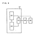
- FIG. 9 shows a fuel cell comprising switching means capable of switching the connection of a plurality of cell blocks each containing a single or plurality of the electrolyte membrane-electrode assemblies described above, in series or parallel.
- a substrate 41 is provided with two sets of cell blocks 40 each containing a single or plurality of electrolyte membrane-electrode assemblies.
- each cell block comprises a plurality of electrolyte membrane-electrode assemblies connected in series or parallel; however, it may also comprise a single electrolyte membrane-electrode assembly.
- the two sets of the cell blocks and switching means 43 for switching the connection thereof constitute a power source unit.
- voltage detecting means 48 and controlling means 49 are connected to the power source unit.
- the controlling means 49 controls the switching means 43 to connect the cell blocks 40 in series when a voltage detected by the voltage detecting means 48 is lower than a predetermined value, and to connect the cell blocks in parallel when the detected voltage is higher than a predetermined value.
- the output of the cell may sometimes be input to the device through a DC-DC converter, in order to supply stable voltage and output to the device. This is the case particularly for many of electronic devices capable of being driven by portable power sources. For this reason, these devices are designed to tolerate some variation in input voltage. However, when the output voltage of the cell is outside the input voltage range of the DC-DC converter, the conversion efficiency of the DC-DC converter is significantly reduced, or furthermore, it becomes impossible to drive the device.
- the connection of the cells in the power source unit is switched from parallel to series, or from series to parallel, to temporarily raise or lower the output voltage of the power source unit, thereby making it possible to drive the device.
- the present invention provides a fuel cell capable of driving a device even at low output, for example, immediately after start-up.
- the controlling means 49 operates the switching means 43 to switch the connection of the cell blocks 40 from parallel to series when a voltage detected by the voltage detecting means 48 is lower than a preset value V 1 .
- a reference voltage value with which a voltage detected by the voltage detecting means 48 is compared, is preferably in the vicinity of the input voltage of the device to be driven or that of the lower-limit input value of the DC-DC converter included with the device to be driven.
- the controlling means 49 determines that the voltage is higher than a preset value V 2 . Accordingly, the controlling means operates the switching means 43 to connect the cell blocks in parallel, returning to normal operation.
- Another reference voltage value used as a criterion in the controlling means 49 is a voltage capable of driving the device even in parallel connection, that is, a value obtained by multiplying the number of switchable connections by V 1 .
- the output voltage to be supplied to the load is increased when the output of the fuel cell is decreased as compared with that in normal operation
- the opposite is also possible. More specifically, this is a case where the power consumption of the device is significantly decreased as compared with that in normal operation, in particular, a case where the output voltage of the fuel cell exceeds the upper-limit input voltage value of the DC-DC converter when the fuel cell is nearly in an open circuit condition. This can be avoided by switching the connection of the fuel cell from series to parallel to lower the output voltage of the fuel cell.
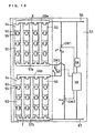
- FIG. 10 shows a more specific embodiment.
- a plurality of electrolyte membrane-electrode assemblies (MEAs) 50 is formed on a substrate 51 in the same manner as in Embodiment 1.
- cell blocks X and Y each containing a plurality of MEAs are formed.
- MEAs 50 are connected in series, and four sets of these are connected in parallel.
- a first catalyst electrode layer 52 serving as the anode of the MEA 50 is connected in series with a second catalyst electrode layer 54 serving as the cathode of the adjacent MEA, by a connector 55.
- the four cell rows thus connected in series are connected in parallel by connectors 56a and 57a or by connectors 56b and 57b.
- the positive and negative terminals of the cell blocks X and Y are connected to output terminals 56 and 57 by a connecting circuit including selector switches SW1, SW2 and SW3. Between the terminals 56 and 57, voltage detecting means 58 and controlling means 59 are connected.
- the controlling means 59 connects the selector switches SW1, SW2 and SW3 to the contact point "s" side when a voltage detected by the voltage detecting means 58 is less than a predetermined value, and to the contact point "p" side when the voltage is a predetermined value or higher. In this manner, the cell blocks A and B are connected in series or parallel.
- the output with respect to the initial output was improved to 70% by the acid solution treatment performed after 1000 hours of operation. This was presumably because impurity ions were removed from the polymer electrolyte membrane by the acid treatment.
- 0 hr 1000 hr 2000 hr Cell A 50 mW/cm 2 40 mW/cm 2 30 mW/cm 2 Cell B 50 mW/cm 2 40 mW/cm 2 36 mW/cm 2
- a power source unit in which the cell blocks X and Y were simply connected in parallel was operated first.
- a device having a voltage of 12 V and a power consumption of 6 mW was used as the device to be driven by this power source unit, and a DC-DC converter having an input of 3 V to 7 V and an output of 12 V was used.
- a humidified hydrogen gas and air were supplied as a fuel and an oxidant gas, respectively, to the power source unit; as a result, an open circuit voltage of 0.91 V was obtained at a cell temperature of 75°C.
- the device was driven when the power source unit was connected to the device and the DC-DC converter.
- the output of the fuel cell at this time was 6.4 mW (3.2 V-2.0 mA).
- the above-described fuel cell was allowed to stand for one week after power generation. Thereafter, when an attempt was made to drive the device at room temperature by supplying a humidified hydrogen gas and air as a fuel and an oxidant, respectively, the device was not driven.
- the output of the power source unit at this time was 6.4 mW (1.6 V-4.0 mA). It was considered that the device was not driven because the output voltage of the fuel cell was below the input voltage range of the DC-DC converter. However, the output gradually increased with time, and after about five minutes, the device became operable.
- the output at this time was 6.3 mW (3.0 V-2.1 mA). This was presumably either because the polymer electrolyte was gradually humidified by the continuous supply of a humidified hydrogen gas thereby to reduce the resistance in the electrolyte, or because the cell temperature increased.
- series-parallel switching was performed for two cell blocks; however, the number of cell blocks for which the switching is performed is not limited to two, and the switching may be performed for three or more plural cell blocks.
- the cell blocks were formed on a same substrate in this example, a similar result can be achieved when they are formed on different substrates.
- the present invention enables a very small fuel cell and the integration of the cells, by using a semiconductor process.
- the polymer electrolyte thin film fuel cell of the present invention has excellent hydrogen ion conductivity, because it employs a hydrogen ion conductive polymer electrolyte membrane having an extremely small thickness. Therefore, the present invention is also effective in that the characteristics of the fuel cell can be improved.
- it is possible to drive a device stably without a great influence by the operation environment such as a cell temperature, outside air temperature and humidity. In particular, a starting-time can be significantly shortened at the time of start-up.
- the impurities contained in the hydrogen ion conductive polymer electrolyte membrane can be removed by treatment with an acid such as nitric acid. Consequently, the fuel cell can be stably operated for a long time.
Landscapes
- Life Sciences & Earth Sciences (AREA)
- Engineering & Computer Science (AREA)
- Manufacturing & Machinery (AREA)
- Sustainable Development (AREA)
- Sustainable Energy (AREA)
- Chemical & Material Sciences (AREA)
- Chemical Kinetics & Catalysis (AREA)
- Electrochemistry (AREA)
- General Chemical & Material Sciences (AREA)
- Fuel Cell (AREA)
Abstract
Description
wherein the second substrate and the above-mentioned substrate are bonded together with back surfaces thereof facing each other, and
a gas flow channel linking the openings is formed between the both substrates.
the fuel cell comprises fuel supply means for supplying, through the openings of the substrate, a liquid organic fuel to the first electrode catalyst layer.
Further, the hydrogen ion conductive polymer electrolyte thin membrane was formed by spin coating in the example described above. However, the hydrogen ion conductive polymer electrolyte thin membrane can be formed by a plasma polymerization process or other production processes.
| 0 hr | 1000 hr | 2000 hr | |
| Cell A | 50 mW/cm2 | 40 mW/cm2 | 30 mW/cm2 |
| Cell B | 50 mW/cm2 | 40 mW/cm2 | 36 mW/cm2 |
| Cell A | Cell B | |
| Fe3+ | 0.8% | 0.1% |
| Ca2+ | 0.15% | 0.03% |
| Na+ | 0.11% | 0.02% |
Claims (13)
- A polymer electrolyte thin film fuel cell comprising:a substrate having a plurality of openings;an electrolyte membrane-electrode assembly formed on said substrate so as to cover each of said openings, said assembly comprising a first catalyst electrode layer, a hydrogen ion conductive polymer electrolyte membrane and a second catalyst electrode layer which are formed successively; andfuel and oxidant supply means for supplying a fuel or an oxidant gas to said first catalyst electrode layer through said openings, and an oxidant gas or a fuel to said second catalyst electrode layer.
- The polymer electrolyte fuel cell in accordance with claim 1,
wherein said electrolyte membrane-electrode assembly is connected in series or parallel. - The polymer electrolyte thin film fuel cell in accordance with claim 2, comprising a second substrate which comprises a plurality of openings and an electrolyte membrane-electrode assembly formed so as to cover each of said openings, said assembly comprising a first catalyst electrode layer, a hydrogen ion conductive polymer electrolyte membrane and a second catalyst electrode layer which are formed successively, said assembly being connected in series or parallel,
wherein said second substrate and said substrate are bonded together with back surfaces thereof facing each other, and
an oxidant gas or fuel gas flow channel linking said openings is formed between said substrates. - The polymer electrolyte thin film fuel cell in accordance with claim 1,
wherein said first catalyst electrode layer and second catalyst electrode layer are porous. - The polymer electrolyte thin film fuel cell in accordance with claim 1,
wherein a hydrogen selective permeable film is laminated on a surface of a catalyst electrode layer to which a fuel is supplied. - The polymer electrolyte thin film fuel cell in accordance with claim 1,
wherein said electrolyte membrane constituting said electrolyte membrane-electrode assembly comprises a laminate of a hydrogen ion conductive polymer electrolyte membrane and a water retaining material film. - The polymer electrolyte thin film fuel cell in accordance with claim 1,
wherein said electrolyte membrane constituting said electrolyte membrane-electrode assembly comprises a laminate of a hydrogen ion conductive polymer electrolyte membrane and an anti-crossover film. - The polymer electrolyte thin film fuel cell in accordance with claim 5,
wherein said electrolyte membrane constituting said electrolyte membrane-electrode assembly comprises a laminate of a hydrogen ion conductive polymer electrolyte membrane and a hydrogen selective permeable film, and
said fuel cell comprises fuel supply means for supplying, through said openings of said substrate, a liquid organic fuel to said first electrode catalyst layer. - The polymer electrolyte thin film fuel cell in accordance with claim 1, comprising:a plurality of cell blocks each containing a single or plurality of electrolyte membrane-electrode assemblies;connecting means for connecting said cell blocks in series or parallel; andcontrolling means for controlling said connecting means to switch said cell blocks from series to parallel, or from parallel to series.
- The polymer electrolyte thin film fuel cell in accordance with claim 1, comprising:at least two sets of cell blocks each containing a single or plurality of electrolyte membrane-electrode assemblies;connecting means for connecting said cell blocks in series or parallel;voltage detecting means for detecting an output voltage of said cell blocks; andcontrolling means for controlling said connecting means to connect said cell blocks in series when a voltage detected by said voltage detecting means is lower than a predetermined value and for controlling said connecting means to connect said cell blocks in parallel when said voltage is higher than a predetermined value.
- A method of manufacturing a polymer electrolyte thin film fuel cell, said method comprising the steps of:successively forming on a substrate, a first catalyst electrode layer, a hydrogen ion conductive polymer electrolyte membrane and a second catalyst electrode layer, thereby producing an electrolyte membrane-electrode assembly; andforming on a back surface of said substrate at a portion thereof corresponding to said electrolyte membrane-electrode assembly, an opening for exposing said first catalyst electrode layer.
- The method of manufacturing a polymer electrolyte thin film fuel cell in accordance with claim 11,
wherein said first or second catalyst electrode layer is formed from an alloy of a metal having catalytic action and a metal having no catalytic action, followed by removing said metal having no catalytic action from said first or second catalyst electrode layer in said step of forming said openings, thereby making said first or second catalyst electrode layer porous. - A method of operating a polymer electrolyte thin film fuel cell, comprising the step of filling an acid solution in a gas flow channel or liquid organic fuel channel to replace a cation impurity trapped in said hydrogen ion conductive polymer electrolyte membrane, after operating the polymer electrolyte fuel cell in accordance with claim 1 for a certain period of time or when a predetermined output decrease is observed in the fuel cell, thereby removing said impurity from the fuel cell.
Applications Claiming Priority (3)
| Application Number | Priority Date | Filing Date | Title |
|---|---|---|---|
| JP2001096953 | 2001-03-29 | ||
| JP2001096953 | 2001-03-29 | ||
| PCT/JP2002/002938 WO2002080299A1 (en) | 2001-03-29 | 2002-03-26 | High-polymer electrolyte type thin film fuel cell and its driving method |
Publications (3)
| Publication Number | Publication Date |
|---|---|
| EP1294039A1 true EP1294039A1 (en) | 2003-03-19 |
| EP1294039A4 EP1294039A4 (en) | 2008-04-30 |
| EP1294039B1 EP1294039B1 (en) | 2010-01-13 |
Family
ID=18950806
Family Applications (1)
| Application Number | Title | Priority Date | Filing Date |
|---|---|---|---|
| EP02707165A Expired - Lifetime EP1294039B1 (en) | 2001-03-29 | 2002-03-26 | Thin film polymer electrolyte fuel cell and method of operating the same |
Country Status (4)
| Country | Link |
|---|---|
| EP (1) | EP1294039B1 (en) |
| JP (1) | JP4196374B2 (en) |
| DE (1) | DE60235058D1 (en) |
| WO (1) | WO2002080299A1 (en) |
Cited By (14)
| Publication number | Priority date | Publication date | Assignee | Title |
|---|---|---|---|---|
| WO2004012289A2 (en) * | 2002-07-26 | 2004-02-05 | Motorola, Inc. | Low loss fuel cell configuration |
| DE10255736A1 (en) * | 2002-11-29 | 2004-06-17 | Micronas Gmbh | Fuel cell with fuel supply device and method for production |
| EP1521327A2 (en) * | 2003-09-29 | 2005-04-06 | Hewlett-Packard Development Company, L.P. | Fuel cell modulation and temperature control |
| DE102006026257A1 (en) * | 2006-06-02 | 2007-12-06 | Micronas Gmbh | Power supply by means of fuel cells |
| WO2009105896A1 (en) * | 2008-02-29 | 2009-09-03 | Angstrom Power Incorporated | Electrochemical cell and membranes related thereto |
| FR2936104A1 (en) * | 2008-09-12 | 2010-03-19 | Rech S De L Ecole Nationale Su | Process to conduct the operation of a fuel cell, comprises introducing a determined quantity of catalyst in a hydrogen stream or oxygen stream for the hydrolysis of sulfonic anhydrides formed during the functioning of the cell |
| WO2010086003A1 (en) | 2009-01-28 | 2010-08-05 | Micronas Gmbh | Fuel cell and method for producing the same |
| US8232025B2 (en) | 2004-05-04 | 2012-07-31 | SOCIéTé BIC | Electrochemical cells having current-carrying structures underlying electrochemical reaction layers |
| US8252479B2 (en) | 2003-06-26 | 2012-08-28 | Dai Nippon Printing Co., Ltd. | Solid oxide fuel cell |
| US8551637B2 (en) | 2004-05-04 | 2013-10-08 | Societe Bic | Membranes and electrochemical cells incorporating such membranes |
| US8790842B2 (en) | 2007-09-25 | 2014-07-29 | Societe Bic | Fuel cell systems including space-saving fluid plenum and related methods |
| WO2015086888A1 (en) * | 2013-12-12 | 2015-06-18 | Nokia Technologies Oy | Electronic apparatus and associated methods |
| CN113678293A (en) * | 2019-04-26 | 2021-11-19 | 株式会社日立高新技术 | Fuel cell unit, fuel cell system, and leak detection method |
| EP4057401A4 (en) * | 2019-11-07 | 2024-01-24 | Hitachi High Tech Corp | Fuel battery cell and method for manufacturing fuel battery cell |
Families Citing this family (21)
| Publication number | Priority date | Publication date | Assignee | Title |
|---|---|---|---|---|
| US7018734B2 (en) | 2001-07-27 | 2006-03-28 | Hewlett-Packard Development Company, L.P. | Multi-element thin-film fuel cell |
| US7112296B2 (en) | 2002-10-18 | 2006-09-26 | Hewlett-Packard Development Company, L.P. | Method for making thin fuel cell electrolyte |
| US7067215B2 (en) * | 2002-10-31 | 2006-06-27 | Hewlett-Packard Development Company, L.P. | Fuel cell and method of manufacturing same using chemical/mechanical planarization |
| US7517601B2 (en) * | 2002-12-09 | 2009-04-14 | Dai Nippon Printing Co., Ltd. | Solid oxide fuel cell |
| US7422814B2 (en) * | 2003-01-29 | 2008-09-09 | Honda Motor Co., Ltd. | Fuel cell system |
| JP4236156B2 (en) * | 2003-01-31 | 2009-03-11 | 日立マクセル株式会社 | Fuel cell |
| JP4123479B2 (en) * | 2003-03-06 | 2008-07-23 | 日産自動車株式会社 | Single cell for fuel cell, method for producing the same, and solid oxide fuel cell |
| JP3945440B2 (en) * | 2003-03-31 | 2007-07-18 | セイコーエプソン株式会社 | FUEL CELL, ITS MANUFACTURING METHOD, ELECTRONIC DEVICE, AND AUTOMOBILE |
| JP4583722B2 (en) * | 2003-04-25 | 2010-11-17 | パナソニック株式会社 | Method for detecting pinhole and method for producing membrane electrode assembly |
| US7049024B2 (en) | 2003-04-30 | 2006-05-23 | Hewlett-Packard Development Company, L.P. | Membrane electrode assemblies and method for manufacture |
| US7521145B2 (en) * | 2003-10-16 | 2009-04-21 | Wistron Corp. | Fuel cells for use in portable devices |
| JP3912384B2 (en) * | 2004-02-10 | 2007-05-09 | セイコーエプソン株式会社 | Manufacturing method of fuel cell |
| JP2005285356A (en) * | 2004-03-26 | 2005-10-13 | Mitsubishi Electric Corp | Membrane electrode assembly for fuel cell and its manufacturing method |
| JP2007103281A (en) * | 2005-10-07 | 2007-04-19 | Toyota Motor Corp | Fuel cell and its manufacturing method |
| EP2182572A4 (en) | 2007-08-02 | 2016-10-19 | Sharp Kk | Fuel cell stack and fuel cell system |
| JP5290402B2 (en) * | 2009-04-01 | 2013-09-18 | シャープ株式会社 | Fuel cell stack and electronic device including the same |
| JP2014123481A (en) * | 2012-12-21 | 2014-07-03 | Magunekusu Kk | Fuel battery cell, fuel cell stack, and methods of manufacturing the same |
| JP6638681B2 (en) | 2017-03-27 | 2020-01-29 | 株式会社豊田中央研究所 | Fuel cell |
| JP6457126B1 (en) * | 2018-02-15 | 2019-01-23 | カルソニックカンセイ株式会社 | Fuel cell and manufacturing method thereof |
| US20220384835A1 (en) * | 2019-11-07 | 2022-12-01 | Hitachi High-Tech Corporation | Fuel Cell Array and Fuel Cell Inspection Method |
| WO2021240722A1 (en) * | 2020-05-28 | 2021-12-02 | 株式会社日立ハイテク | Fuel battery module and fuel battery system |
Citations (2)
| Publication number | Priority date | Publication date | Assignee | Title |
|---|---|---|---|---|
| DE19914681A1 (en) * | 1999-03-31 | 2000-10-05 | Joerg Mueller | Miniature polymer electrolyte membrane fuel cell, used in microsystems, has a structure produced by a combination of thin film, microsystem etching and glass-silicon bonding technologies |
| WO2001037357A2 (en) * | 1999-11-17 | 2001-05-25 | Neah Power Systems, Inc. | Fuel cells having silicon substrates and/or sol-gel derived support structures |
Family Cites Families (5)
| Publication number | Priority date | Publication date | Assignee | Title |
|---|---|---|---|---|
| JPH0864216A (en) * | 1994-08-25 | 1996-03-08 | Tonen Corp | Oxygen ion conductor thin film and manufacture thereof |
| JP4296625B2 (en) * | 1999-03-15 | 2009-07-15 | ソニー株式会社 | Power generation device |
| JP3290169B2 (en) * | 2000-02-24 | 2002-06-10 | 雅則 奥山 | Micro fuel cell |
| JP4686819B2 (en) * | 2000-06-02 | 2011-05-25 | ソニー株式会社 | Fuel cell |
| JP2002015763A (en) * | 2000-06-30 | 2002-01-18 | Toshiba Corp | Fuel cell and its manufacturing method |
-
2002
- 2002-03-26 JP JP2002578596A patent/JP4196374B2/en not_active Expired - Fee Related
- 2002-03-26 EP EP02707165A patent/EP1294039B1/en not_active Expired - Lifetime
- 2002-03-26 DE DE60235058T patent/DE60235058D1/en not_active Expired - Lifetime
- 2002-03-26 WO PCT/JP2002/002938 patent/WO2002080299A1/en active Application Filing
Patent Citations (2)
| Publication number | Priority date | Publication date | Assignee | Title |
|---|---|---|---|---|
| DE19914681A1 (en) * | 1999-03-31 | 2000-10-05 | Joerg Mueller | Miniature polymer electrolyte membrane fuel cell, used in microsystems, has a structure produced by a combination of thin film, microsystem etching and glass-silicon bonding technologies |
| WO2001037357A2 (en) * | 1999-11-17 | 2001-05-25 | Neah Power Systems, Inc. | Fuel cells having silicon substrates and/or sol-gel derived support structures |
Non-Patent Citations (4)
| Title |
|---|
| KELLEY S C ET AL: "A MINIATURE METHANOL/AIR POLYMER ELECTROLYTE FUEL CELL" September 2000 (2000-09), ELECTROCHEMICAL AND SOLID-STATE LETTERS, IEEE SERVICE CENTER, PISCATAWAY, NJ, US, PAGE(S) 407-409 , XP001023907 ISSN: 1099-0062 Chapter: Experimental * page 407 - page 408; figure 2 * * |
| MORSE JEFFREY D ET AL: "Novel proton exchange membrane thin-film fuel cell for microscale energy conversion" JOURNAL OF VACUUM SCIENCE AND TECHNOLOGY A. VACUUM, SURFACES AND FILMS, AMERICAN INSTITUTE OF PHYSICS, NEW YORK, NY, US, vol. 18, no. 4, July 2000 (2000-07), pages 2003-2005, XP012005262 ISSN: 0734-2101 * |
| See also references of WO02080299A1 * |
| WOO YOUNG SIM ET AL: "Fabrication of micro power source [MPS] using a micro direct methanol fuel cell [/spl mu/DMFC] for the medical application" 21 January 2001 (2001-01-21), PROCEEDINGS OF THE IEEE 14TH. ANNUAL INTERNATIONAL CONFERENCE ON MICROELECTRO MECHANICAL SYSTEMS. MEMS 2001. INTERLAKEN, SWITZERLAND, JAN. 21 - 25, 2001, IEEE INTERNATIONAL MICRO ELECTRO MECHANICAL SYSTEMS CONFERENCE, NEW YORK, NY : IEEE, US, PAGE(S) , XP010534620 ISBN: 0-7803-5998-4 Chapters: Experimental, Design * page 343 - page 343; figure 5 * * |
Cited By (28)
| Publication number | Priority date | Publication date | Assignee | Title |
|---|---|---|---|---|
| WO2004012289A3 (en) * | 2002-07-26 | 2004-12-16 | Motorola Inc | Low loss fuel cell configuration |
| WO2004012289A2 (en) * | 2002-07-26 | 2004-02-05 | Motorola, Inc. | Low loss fuel cell configuration |
| DE10255736B4 (en) * | 2002-11-29 | 2009-03-19 | Micronas Gmbh | Fuel cell and method of manufacture |
| DE10255736A1 (en) * | 2002-11-29 | 2004-06-17 | Micronas Gmbh | Fuel cell with fuel supply device and method for production |
| US8741499B2 (en) | 2003-06-26 | 2014-06-03 | Dai Nippon Printing Co., Ltd. | Solid oxide fuel cell |
| US8252479B2 (en) | 2003-06-26 | 2012-08-28 | Dai Nippon Printing Co., Ltd. | Solid oxide fuel cell |
| EP1521327A3 (en) * | 2003-09-29 | 2005-07-13 | Hewlett-Packard Development Company, L.P. | Fuel cell modulation and temperature control |
| EP1521327A2 (en) * | 2003-09-29 | 2005-04-06 | Hewlett-Packard Development Company, L.P. | Fuel cell modulation and temperature control |
| US9017892B2 (en) | 2004-05-04 | 2015-04-28 | Societe Bic | Electrochemical cells having current-carrying structures underlying electrochemical reaction layers |
| US8628890B2 (en) | 2004-05-04 | 2014-01-14 | Societe Bic | Electrochemical cells having current-carrying structures underlying electrochemical reaction layers |
| US8551637B2 (en) | 2004-05-04 | 2013-10-08 | Societe Bic | Membranes and electrochemical cells incorporating such membranes |
| US8232025B2 (en) | 2004-05-04 | 2012-07-31 | SOCIéTé BIC | Electrochemical cells having current-carrying structures underlying electrochemical reaction layers |
| DE102006026257A1 (en) * | 2006-06-02 | 2007-12-06 | Micronas Gmbh | Power supply by means of fuel cells |
| US9673476B2 (en) | 2007-09-25 | 2017-06-06 | Intelligent Energy Limited | Fuel cell systems including space-saving fluid plenum and related methods |
| US8790842B2 (en) | 2007-09-25 | 2014-07-29 | Societe Bic | Fuel cell systems including space-saving fluid plenum and related methods |
| US9472817B2 (en) | 2008-02-29 | 2016-10-18 | Intelligent Energy Limited | Electrochemical cell and membranes related thereto |
| WO2009105896A1 (en) * | 2008-02-29 | 2009-09-03 | Angstrom Power Incorporated | Electrochemical cell and membranes related thereto |
| FR2936103A1 (en) * | 2008-09-12 | 2010-03-19 | Rech S De L Ecole Nationale Su | PROCESS FOR THE REJUVENATION OF A POLYMER COMPRISING PENDING CHAINS COMPLETE BY SULFONIC ACID GROUPS METHOD FOR OPERATING THE OPERATION OF A COMBUSTION CELL APPLYING |
| FR2936104A1 (en) * | 2008-09-12 | 2010-03-19 | Rech S De L Ecole Nationale Su | Process to conduct the operation of a fuel cell, comprises introducing a determined quantity of catalyst in a hydrogen stream or oxygen stream for the hydrolysis of sulfonic anhydrides formed during the functioning of the cell |
| WO2010086003A1 (en) | 2009-01-28 | 2010-08-05 | Micronas Gmbh | Fuel cell and method for producing the same |
| EP2216846A1 (en) * | 2009-01-28 | 2010-08-11 | Micronas GmbH | Fuel cells and method for producing same |
| WO2015086888A1 (en) * | 2013-12-12 | 2015-06-18 | Nokia Technologies Oy | Electronic apparatus and associated methods |
| EP3080597A4 (en) * | 2013-12-12 | 2017-06-14 | Nokia Technologies OY | Electronic apparatus and associated methods |
| US9859570B2 (en) | 2013-12-12 | 2018-01-02 | Nokia Technologies Oy | Electronic apparatus and associated methods |
| CN113678293A (en) * | 2019-04-26 | 2021-11-19 | 株式会社日立高新技术 | Fuel cell unit, fuel cell system, and leak detection method |
| US20220181658A1 (en) * | 2019-04-26 | 2022-06-09 | Hitachi High-Tech Corporation | Fuel battery cell, fuel battery system, leak detection method |
| US11855318B2 (en) * | 2019-04-26 | 2023-12-26 | Hitachi High-Tech Corporation | Fuel battery cell, fuel battery system, leak detection method |
| EP4057401A4 (en) * | 2019-11-07 | 2024-01-24 | Hitachi High Tech Corp | Fuel battery cell and method for manufacturing fuel battery cell |
Also Published As
| Publication number | Publication date |
|---|---|
| EP1294039B1 (en) | 2010-01-13 |
| JPWO2002080299A1 (en) | 2004-07-22 |
| WO2002080299A1 (en) | 2002-10-10 |
| JP4196374B2 (en) | 2008-12-17 |
| EP1294039A4 (en) | 2008-04-30 |
| DE60235058D1 (en) | 2010-03-04 |
Similar Documents
| Publication | Publication Date | Title |
|---|---|---|
| US7081317B2 (en) | Polymer electrolyte thin film fuel cell and method of operating the same | |
| EP1294039B1 (en) | Thin film polymer electrolyte fuel cell and method of operating the same | |
| EP1517392B1 (en) | Solid high polymer type cell assembly | |
| JP4284068B2 (en) | Direct methanol fuel cell system with built-in flow field | |
| US7691507B2 (en) | Combination fuel cell and ion pump, and methods and infrastructure systems employing same | |
| EP1859498B1 (en) | Method and device to improve operation of a fuel cell | |
| US6740444B2 (en) | PEM fuel cell with alternating ribbed anodes and cathodes | |
| JP2005527063A (en) | Direct methanol fuel cell with water recovery | |
| US20060105223A1 (en) | Bipolar plate and direct liquid feed fuel cell stack | |
| WO2007062368A2 (en) | Regenerative fuel cell/electrolyzer stack | |
| JP2002270196A (en) | High molecular electrolyte type fuel cell and operating method thereof | |
| JP3358222B2 (en) | Activation method of polymer electrolyte fuel cell | |
| US20090068519A1 (en) | Fuel cell and method of manufacturing the same | |
| JP2000260439A (en) | Stainless steel separator for solid polymer fuel cell, spacer, polymer film, and solid polymer fuel cell | |
| US7521147B2 (en) | Fuel cell comprising current collectors integrated in the electrode-membrane-electrode stack | |
| JP2003282089A (en) | Micro fuel cell | |
| JP2004134130A (en) | Fuel cell stack | |
| KR20060096610A (en) | Membrane electrode assembly for fuel cell, and stack for fuel cell and full cell system comprising the same | |
| KR20070024124A (en) | Separator for fuel cell, method of preparing same and fuel cell system comprising same | |
| KR100612235B1 (en) | A membrane for fuel cell and a fuel cell comprising the same | |
| JP2002141090A (en) | Operation method of solid polymer fuel cell system | |
| JP2002198072A (en) | Solid polymer fuel cell | |
| JP2005141994A (en) | Polyelectrolyte fuel cell | |
| KR100616678B1 (en) | Micro fuel cell and method for manufacturing the same | |
| JP7331825B2 (en) | fuel cell system |
Legal Events
| Date | Code | Title | Description |
|---|---|---|---|
| PUAI | Public reference made under article 153(3) epc to a published international application that has entered the european phase |
Free format text: ORIGINAL CODE: 0009012 |
|
| 17P | Request for examination filed |
Effective date: 20030113 |
|
| AK | Designated contracting states |
Kind code of ref document: A1 Designated state(s): AT BE CH CY DE DK ES FI FR GB GR IE IT LI LU MC NL PT SE TR |
|
| AX | Request for extension of the european patent |
Extension state: AL LT LV MK RO SI |
|
| RIN1 | Information on inventor provided before grant (corrected) |
Inventor name: TANAKA, AOI Inventor name: HOJO, NOBUHIKO Inventor name: FUJII, SATORU Inventor name: OKADA, YUKIHIRO Inventor name: HOSAKA, MASATO Inventor name: NOGUCHI, YASUTAKA Inventor name: YUASA, KOHJI Inventor name: SHIBUTANI, SATOSHI Inventor name: HATOH, KAZUHITO |
|
| A4 | Supplementary search report drawn up and despatched |
Effective date: 20080401 |
|
| RAP1 | Party data changed (applicant data changed or rights of an application transferred) |
Owner name: PANASONIC CORPORATION |
|
| GRAP | Despatch of communication of intention to grant a patent |
Free format text: ORIGINAL CODE: EPIDOSNIGR1 |
|
| 17Q | First examination report despatched |
Effective date: 20090202 |
|
| RTI1 | Title (correction) |
Free format text: THIN FILM POLYMER ELECTROLYTE FUEL CELL AND METHOD OF OPERATING THE SAME |
|
| GRAS | Grant fee paid |
Free format text: ORIGINAL CODE: EPIDOSNIGR3 |
|
| GRAA | (expected) grant |
Free format text: ORIGINAL CODE: 0009210 |
|
| AK | Designated contracting states |
Kind code of ref document: B1 Designated state(s): DE FR GB |
|
| REG | Reference to a national code |
Ref country code: GB Ref legal event code: FG4D |
|
| REF | Corresponds to: |
Ref document number: 60235058 Country of ref document: DE Date of ref document: 20100304 Kind code of ref document: P |
|
| PLBE | No opposition filed within time limit |
Free format text: ORIGINAL CODE: 0009261 |
|
| STAA | Information on the status of an ep patent application or granted ep patent |
Free format text: STATUS: NO OPPOSITION FILED WITHIN TIME LIMIT |
|
| 26N | No opposition filed |
Effective date: 20101014 |
|
| REG | Reference to a national code |
Ref country code: FR Ref legal event code: ST Effective date: 20101130 |
|
| GBPC | Gb: european patent ceased through non-payment of renewal fee |
Effective date: 20100413 |
|
| PG25 | Lapsed in a contracting state [announced via postgrant information from national office to epo] |
Ref country code: FR Free format text: LAPSE BECAUSE OF NON-PAYMENT OF DUE FEES Effective date: 20100331 |
|
| PG25 | Lapsed in a contracting state [announced via postgrant information from national office to epo] |
Ref country code: GB Free format text: LAPSE BECAUSE OF NON-PAYMENT OF DUE FEES Effective date: 20100413 |
|
| PGFP | Annual fee paid to national office [announced via postgrant information from national office to epo] |
Ref country code: DE Payment date: 20170321 Year of fee payment: 16 |
|
| REG | Reference to a national code |
Ref country code: DE Ref legal event code: R119 Ref document number: 60235058 Country of ref document: DE |
|
| PG25 | Lapsed in a contracting state [announced via postgrant information from national office to epo] |
Ref country code: DE Free format text: LAPSE BECAUSE OF NON-PAYMENT OF DUE FEES Effective date: 20181002 |