EP1293677A2 - Pumpe im Ventilgehäuse - Google Patents
Pumpe im Ventilgehäuse Download PDFInfo
- Publication number
- EP1293677A2 EP1293677A2 EP02018432A EP02018432A EP1293677A2 EP 1293677 A2 EP1293677 A2 EP 1293677A2 EP 02018432 A EP02018432 A EP 02018432A EP 02018432 A EP02018432 A EP 02018432A EP 1293677 A2 EP1293677 A2 EP 1293677A2
- Authority
- EP
- European Patent Office
- Prior art keywords
- pump
- impeller
- valve
- valve housing
- pump according
- Prior art date
- Legal status (The legal status is an assumption and is not a legal conclusion. Google has not performed a legal analysis and makes no representation as to the accuracy of the status listed.)
- Granted
Links
Images

Classifications
-
- F—MECHANICAL ENGINEERING; LIGHTING; HEATING; WEAPONS; BLASTING
- F04—POSITIVE - DISPLACEMENT MACHINES FOR LIQUIDS; PUMPS FOR LIQUIDS OR ELASTIC FLUIDS
- F04D—NON-POSITIVE-DISPLACEMENT PUMPS
- F04D13/00—Pumping installations or systems
- F04D13/02—Units comprising pumps and their driving means
- F04D13/06—Units comprising pumps and their driving means the pump being electrically driven
-
- F—MECHANICAL ENGINEERING; LIGHTING; HEATING; WEAPONS; BLASTING
- F04—POSITIVE - DISPLACEMENT MACHINES FOR LIQUIDS; PUMPS FOR LIQUIDS OR ELASTIC FLUIDS
- F04D—NON-POSITIVE-DISPLACEMENT PUMPS
- F04D29/00—Details, component parts, or accessories
- F04D29/04—Shafts or bearings, or assemblies thereof
- F04D29/042—Axially shiftable rotors
-
- F—MECHANICAL ENGINEERING; LIGHTING; HEATING; WEAPONS; BLASTING
- F04—POSITIVE - DISPLACEMENT MACHINES FOR LIQUIDS; PUMPS FOR LIQUIDS OR ELASTIC FLUIDS
- F04D—NON-POSITIVE-DISPLACEMENT PUMPS
- F04D29/00—Details, component parts, or accessories
- F04D29/40—Casings; Connections of working fluid
- F04D29/42—Casings; Connections of working fluid for radial or helico-centrifugal pumps
- F04D29/426—Casings; Connections of working fluid for radial or helico-centrifugal pumps especially adapted for liquid pumps
- F04D29/4293—Details of fluid inlet or outlet
-
- F—MECHANICAL ENGINEERING; LIGHTING; HEATING; WEAPONS; BLASTING
- F04—POSITIVE - DISPLACEMENT MACHINES FOR LIQUIDS; PUMPS FOR LIQUIDS OR ELASTIC FLUIDS
- F04D—NON-POSITIVE-DISPLACEMENT PUMPS
- F04D29/00—Details, component parts, or accessories
- F04D29/60—Mounting; Assembling; Disassembling
- F04D29/605—Mounting; Assembling; Disassembling specially adapted for liquid pumps
Definitions
- Such decentrally arranged pumps have been known for a short time. she replace the previously common central pump, which is located near a boiler is arranged and mostly supplies the heating system of a building alone.
- the decentralized pumps attached to the radiator in particular have the Advantage that their performance can be adapted to the needs of the radiator and make an energy-saving, needs-based supply possible.
- disadvantage of the pumps known to date is that special adapters are required for their assembly are that have to be integrated into the piping system as separate components. Retrofitting existing heating systems with the pumps mentioned is therefore comparatively complex.
- the pump according to the invention ultimately takes on the same function as that Thermostatic valve, namely the hot water flow through the radiator
- the Operation of the pump is similar to the operation of the thermostatic valve, so that the user is unable to determine any significant difference.
- the electric motor can be handled by a rotatably mounted Ring, which is equipped with a scale like an adjustment knob and when it is rotated, a control variable relevant for motor control, for example, a target temperature is changed. So for the user is a greatest possible ease of use with an appealing design of the pump given.
- the pump is hidden inconspicuously in the guise of the user Thermostatic valve.
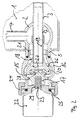
- FIG 1 the "simple" form of the centrifugal pump according to the invention in installed condition shown.
- the corner of a radiator 1 as shown is shown is well known.
- the flow line supplying the radiator points a knee with a flange, which is intended for the installation of a corner valve.
- This forms a spherical valve housing 2 into which an inlet line 3 protrudes with its nozzle 7 and into which a drain line 4 opens.
- the valve housing 2 arranged within the facing 6 of the radiator 1 also has a suitable for connecting a thermostatic valve Connection piece 5 with end flange, which protrudes from the facing 6, the connecting piece 5 is welded to the facing 6.
- the pump itself has a drive on its electrical side Electric motor 8 and on the hydraulic side a held on the shaft 9 Impeller 10 on.
- the impeller 10 sits with its central suction mouth 11 directly on the nozzle 7 of the inlet line 3 and thus takes the position and in a way in the valve housing 2 the function of a valve member in covering state, wherein the valve housing 2 which the impeller 10th surrounding impeller chamber forms.
- On the hydraulic side of the pump is in End shield 13 an external thread 12 is provided, which forms a closure means and by means of which the pump can be screwed onto the valve housing 2.
- To the Screwing in the connecting piece 5 has a corresponding internal thread.
- the seal between the pump and the connector 5 is done by means of an O-ring 14.
- the dimensions of the screw-in pump are adapted according to the existing circumstances.
- Figure 2 also shows the corner of a radiator 1 with one in it located spherical valve housing 2.
- the pump by means of an adapter forming an impeller chamber 15 16 screwed to the connecting piece 5, the adapter 16 the Inlet line 3 to the suction mouth 11 of the impeller 17 with an attachment 18 extended.
- the attachment 18 has a pipe section 19 which is connected to the connector 7 is attached.
- the attachment 18 has a hydraulic insert 20 which with its hole forms the inlet to the suction mouth and the one with its hydrodynamically designed surface forms an outlet channel and Defines the geometry of the impeller chamber 15. The outlet of the impeller chamber Ultimately opens axially in the valve housing 2 and thus in the drain line 4.
Landscapes
- Engineering & Computer Science (AREA)
- Mechanical Engineering (AREA)
- General Engineering & Computer Science (AREA)
- Structures Of Non-Positive Displacement Pumps (AREA)
- Steam Or Hot-Water Central Heating Systems (AREA)
Abstract
Description
- Figur 1
- eine in ein Ventilgehäuse hineinragende Pumpe und
- Figur 2
- eine vermittels eines Adapters an ein Ventilgehäuse angebrachte Pumpe.
Claims (10)
- Kreiselpumpe zur dezentralen Versorgung eines mehrere Heizkörper aufweisenden Heizkreislaufes eines Gebäudes mit einem auf der elektrischen Seite angeordneten und die Pumpe antreibenden Elektromotor und mit einem auf der hydraulischen Seite befindlichen Laufrad, das einen zentralen Saugmund aufweist, wobei die Kreiselpumpe an einem Heizkkörper oder in unmittelbarer Nähe eines Heizkkörpers in dessen Vor- oder Rücklauf angeordnet ist,
gekennzeichnet durch
ein auf der hydraulischen Seite befindliches Verschlußmittel, insbesondere ein Gewinde (12), mit dem die Pumpe derart an einem eine Zulaufleitung (3) und eine Ablaufleitung (4) aufweisenden Ventilgehäuse (2) anbringbar ist, daß der Saugmund (11) die Zulaufleitung (3) umgibt und das Laufrad (3) die Funktion des die Zulaufleitung (3) bedeckenden Ventilgliedes einnimmt. - Pumpe nach Anspruch 1,
dadurch gekennzeichnet, daß bei montierter Pumpe das Laufrad (10) die Position des Ventilgliedes im Ventilgehäuse (2) einnimmt und mit seinem Saugmund (11) direkt auf den Stutzen (7) der Zulaufleitung (3) aufgesetzt ist, wobei das Ventilgehäuse (2) selber eine Laufradkammer bildet. - Pumpe nach Anspruch 1,
gekennzeichnet durcheinen eine Laufradkammer (15) ausbildenden Adapter (16), der die Zulaufleitung (3) zum Saugmund (11) des Laufrades (20) hin verlängert, wobei ein Auslaß (10) der Laufradkammer (15) in die Ablaufleitung (4) mündet. - Pumpe nach einem der vorherigen Ansprüche,
dadurch gekennzeichnet, daß das Verschlußmittel ein koaxial zum Saugmund angeordnetes Außengewinde (12, 21) ist. - Pumpe nach einem der vorherigen Ansprüche,
dadurch gekennzeichnet, daß der Elektromotor von einem drehbar gelagerten Ring umgeben ist, bei dessen Verdrehung eine für die Motorregelung relevante Regelgröße verändert wird. - Pumpe nach einem der vorherigen Ansprüche,
dadurch gekennzeichnet, daß das Verschlußmittel an einem die elektrische Seite von der hydraulischen Seite trennenden Lagerschild (13) angebracht ist. - Pumpe nach einem der vorherigen Ansprüche,
dadurch gekennzeichnet, daß das Verschlußmittel von einem Dichtring (14) umgeben ist, der die Pumpe gegen das Ventilgehäuse (2) abdichtet. - Pumpe nach einem der vorherigen Ansprüche,
gekennzeichnet durch ein Ventil, das von Außen schaltbar ist und das im geschlossenen Zustand den Leckstrom durch das stehende Laufrad verhindert. - Verwendung einer für den Einbau eines Ventiles, insbesondere eines Thermostatventiles, vorgesehenen Aufnahme im Vor- oder Rücklauf eines Heiz- oder Kühlkörpers zum Einbau einer Pumpe nach einem der vorherigen Ansprüche.
- Heiz- oder Kühlkörper mit einem in der Vor- oder Rücklaufleitung angeordneten Anschlußmittel, insbesondere einem Ventilgehäuse, zum Anschluß eines Hydraulikelementes, wobei das Anschlußmittel einen Raum aufweist, in dem eine Zulaufleitung und eine Ablaufleitung münden,
dadurch gekennzeichnet, daß
am Anschlußmittel eine Kreiselpumpe als Hydraulikelement lösbar befestigt ist, die das flüssige Heiz- oder Kühlmedium aus der Zulaufleitung ansaugt und in die Ablaufleitung pumpt.
Applications Claiming Priority (2)
| Application Number | Priority Date | Filing Date | Title |
|---|---|---|---|
| DE10145410A DE10145410A1 (de) | 2001-09-14 | 2001-09-14 | Pumpe im Ventilgehäuse |
| DE10145410 | 2001-09-14 |
Publications (3)
| Publication Number | Publication Date |
|---|---|
| EP1293677A2 true EP1293677A2 (de) | 2003-03-19 |
| EP1293677A3 EP1293677A3 (de) | 2004-01-14 |
| EP1293677B1 EP1293677B1 (de) | 2009-01-21 |
Family
ID=7699077
Family Applications (1)
| Application Number | Title | Priority Date | Filing Date |
|---|---|---|---|
| EP02018432A Expired - Lifetime EP1293677B1 (de) | 2001-09-14 | 2002-08-16 | Heiz- oder Kühlkörper |
Country Status (2)
| Country | Link |
|---|---|
| EP (1) | EP1293677B1 (de) |
| DE (2) | DE10145410A1 (de) |
Cited By (1)
| Publication number | Priority date | Publication date | Assignee | Title |
|---|---|---|---|---|
| FR2974866A1 (fr) * | 2011-05-03 | 2012-11-09 | Francois Gerlier | Pompe de circulation d'electrolyte pour engin marin |
Families Citing this family (1)
| Publication number | Priority date | Publication date | Assignee | Title |
|---|---|---|---|---|
| DE102004021988A1 (de) * | 2004-05-04 | 2005-11-24 | Wilo Ag | Verfahren zum Entlüften einer Kreiselpumpe |
Family Cites Families (10)
| Publication number | Priority date | Publication date | Assignee | Title |
|---|---|---|---|---|
| SE316376B (de) * | 1966-11-04 | 1969-10-20 | Svenska Maskinverken Ab | |
| US3664760A (en) * | 1970-09-02 | 1972-05-23 | Coleco Ind Inc | Centrifugal pump |
| CH558475A (de) * | 1972-09-05 | 1975-01-31 | Saurer Ag Adolph | Anordnung zum messen der temperatur einer von einer pumpe gefoerderten fluessigkeit. |
| DE2510787A1 (de) * | 1975-03-08 | 1976-09-16 | Vaillant Joh Kg | Pumpe |
| DE4031164A1 (de) * | 1990-10-03 | 1992-04-09 | Oplaender Wilo Werk Gmbh | Adapter fuer pumpen |
| DE4407447C2 (de) * | 1994-03-07 | 1999-04-29 | Oventrop Sohn Kg F W | Voreinstellbares Regulierventil |
| DE29704753U1 (de) * | 1997-03-15 | 1997-05-15 | Grundfos A/S, Bjerringbro | Gießbares Pumpengehäuse für ein Motorpumpenaggregat zur Montage an einer ebenen Wandfläche einer Vorrichtung |
| DE19711178A1 (de) * | 1997-03-18 | 1998-09-24 | Wilo Gmbh | Pumpe im Warmwasserkreislauf einer Zentralheizung |
| DE19743159C2 (de) * | 1997-09-30 | 2000-08-31 | Berg Hans Gmbh & Co Kg | Ventilheizkörper |
| DE19842174A1 (de) * | 1998-09-15 | 2000-03-16 | Wilo Gmbh | Pumpenregelung |
-
2001
- 2001-09-14 DE DE10145410A patent/DE10145410A1/de not_active Withdrawn
-
2002
- 2002-08-16 DE DE50213231T patent/DE50213231D1/de not_active Expired - Lifetime
- 2002-08-16 EP EP02018432A patent/EP1293677B1/de not_active Expired - Lifetime
Cited By (1)
| Publication number | Priority date | Publication date | Assignee | Title |
|---|---|---|---|---|
| FR2974866A1 (fr) * | 2011-05-03 | 2012-11-09 | Francois Gerlier | Pompe de circulation d'electrolyte pour engin marin |
Also Published As
| Publication number | Publication date |
|---|---|
| EP1293677A3 (de) | 2004-01-14 |
| EP1293677B1 (de) | 2009-01-21 |
| DE50213231D1 (de) | 2009-03-12 |
| DE10145410A1 (de) | 2003-04-03 |
Similar Documents
| Publication | Publication Date | Title |
|---|---|---|
| DE102013018205B3 (de) | Regelbare Kühlmittelpumpe | |
| DE3839689C2 (de) | Baukastenartig aufbaubares, elektromotorisch angetriebenes hydraulisches Pumpenaggregat | |
| DE112013001963B4 (de) | Schmiermittelentlüftungsventil mit Schrittmotor-Antrieb | |
| DE3831457A1 (de) | Elektromotorisch angetriebene fluessigkeitspumpe | |
| DE9113745U1 (de) | Thermostatisch regelbarer Heizkörperventil - Umbausatz | |
| EP3140530B1 (de) | Agbasturbolader mit einem waste-gate-ventil | |
| DE19711178A1 (de) | Pumpe im Warmwasserkreislauf einer Zentralheizung | |
| EP0918197B2 (de) | Baueinheit für eine Kompaktheizungsanlage | |
| EP0529353A1 (de) | Gastherme | |
| EP1293677B1 (de) | Heiz- oder Kühlkörper | |
| EP3516230A1 (de) | Schraubenkompressorsystem für ein nutzfahrzeug | |
| DE10222758A1 (de) | Kühlmittelpumpe für einen Kühlkreislauf einer Brennkraftmaschine und Drehschieberventil | |
| EP1343645B1 (de) | Fahrzeugheizgerät mit integrierter wärmeträger-umwälzpumpe | |
| DE10035458C2 (de) | Kombi-Meßfühler | |
| EP3559471A1 (de) | Pumpenanordnung und nuklearreaktor mit einer solchen pumpenanordnung | |
| DE102006034275B4 (de) | Warmwasserbereiter | |
| DE19854848B4 (de) | Anschlusseinrichtung für Heizkörper | |
| EP1504514A1 (de) | Elektromotor zur verwendung als pumpenmotor und pumpe | |
| EP1033495B1 (de) | Serviceadapter für ein Heizungs-oder Kühlsystem | |
| EP1328356A1 (de) | Hochdruckreinigungsgerät | |
| DE102005007141A1 (de) | Ventil | |
| DE102022213733A1 (de) | Zentrifugalpumpenanordnung | |
| DE102013101792B4 (de) | Wärmepumpe | |
| EP2944825B1 (de) | Pumpengehäuse mit drei Stutzen | |
| DE602004005297T2 (de) | Kreiselpumpe für Waschmaschinen |
Legal Events
| Date | Code | Title | Description |
|---|---|---|---|
| PUAI | Public reference made under article 153(3) epc to a published international application that has entered the european phase |
Free format text: ORIGINAL CODE: 0009012 |
|
| AK | Designated contracting states |
Kind code of ref document: A2 Designated state(s): AT BE BG CH CY CZ DE DK EE ES FI FR GB GR IE IT LI LU MC NL PT SE SK TR |
|
| AX | Request for extension of the european patent |
Extension state: AL LT LV MK RO SI |
|
| PUAL | Search report despatched |
Free format text: ORIGINAL CODE: 0009013 |
|
| AK | Designated contracting states |
Kind code of ref document: A3 Designated state(s): AT BE BG CH CY CZ DE DK EE ES FI FR GB GR IE IT LI LU MC NL PT SE SK TR |
|
| AX | Request for extension of the european patent |
Extension state: AL LT LV MK RO SI |
|
| RIC1 | Information provided on ipc code assigned before grant |
Ipc: 7F 04D 13/06 A Ipc: 7F 04D 29/60 B Ipc: 7F 04D 29/42 B |
|
| 17P | Request for examination filed |
Effective date: 20040225 |
|
| AKX | Designation fees paid |
Designated state(s): DE FR GB IT |
|
| 17Q | First examination report despatched |
Effective date: 20070829 |
|
| RTI1 | Title (correction) |
Free format text: HEATING OR COOLING RADIATOR |
|
| GRAP | Despatch of communication of intention to grant a patent |
Free format text: ORIGINAL CODE: EPIDOSNIGR1 |
|
| GRAS | Grant fee paid |
Free format text: ORIGINAL CODE: EPIDOSNIGR3 |
|
| RAP1 | Party data changed (applicant data changed or rights of an application transferred) |
Owner name: WILO SE |
|
| GRAA | (expected) grant |
Free format text: ORIGINAL CODE: 0009210 |
|
| AK | Designated contracting states |
Kind code of ref document: B1 Designated state(s): DE FR GB IT |
|
| REG | Reference to a national code |
Ref country code: GB Ref legal event code: FG4D Free format text: NOT ENGLISH |
|
| REF | Corresponds to: |
Ref document number: 50213231 Country of ref document: DE Date of ref document: 20090312 Kind code of ref document: P |
|
| PLBE | No opposition filed within time limit |
Free format text: ORIGINAL CODE: 0009261 |
|
| STAA | Information on the status of an ep patent application or granted ep patent |
Free format text: STATUS: NO OPPOSITION FILED WITHIN TIME LIMIT |
|
| 26N | No opposition filed |
Effective date: 20091022 |
|
| PGFP | Annual fee paid to national office [announced via postgrant information from national office to epo] |
Ref country code: GB Payment date: 20140813 Year of fee payment: 13 |
|
| REG | Reference to a national code |
Ref country code: FR Ref legal event code: PLFP Year of fee payment: 14 |
|
| PGFP | Annual fee paid to national office [announced via postgrant information from national office to epo] |
Ref country code: DE Payment date: 20150902 Year of fee payment: 14 |
|
| PGFP | Annual fee paid to national office [announced via postgrant information from national office to epo] |
Ref country code: FR Payment date: 20150828 Year of fee payment: 14 |
|
| PGFP | Annual fee paid to national office [announced via postgrant information from national office to epo] |
Ref country code: IT Payment date: 20150831 Year of fee payment: 14 |
|
| GBPC | Gb: european patent ceased through non-payment of renewal fee |
Effective date: 20150816 |
|
| PG25 | Lapsed in a contracting state [announced via postgrant information from national office to epo] |
Ref country code: GB Free format text: LAPSE BECAUSE OF NON-PAYMENT OF DUE FEES Effective date: 20150816 |
|
| REG | Reference to a national code |
Ref country code: DE Ref legal event code: R119 Ref document number: 50213231 Country of ref document: DE |
|
| REG | Reference to a national code |
Ref country code: FR Ref legal event code: ST Effective date: 20170428 |
|
| PG25 | Lapsed in a contracting state [announced via postgrant information from national office to epo] |
Ref country code: DE Free format text: LAPSE BECAUSE OF NON-PAYMENT OF DUE FEES Effective date: 20170301 Ref country code: FR Free format text: LAPSE BECAUSE OF NON-PAYMENT OF DUE FEES Effective date: 20160831 |
|
| PG25 | Lapsed in a contracting state [announced via postgrant information from national office to epo] |
Ref country code: IT Free format text: LAPSE BECAUSE OF NON-PAYMENT OF DUE FEES Effective date: 20160816 |