EP1292736B1 - Einlaufgarnitur für einen spülkasten - Google Patents
Einlaufgarnitur für einen spülkasten Download PDFInfo
- Publication number
- EP1292736B1 EP1292736B1 EP20010935905 EP01935905A EP1292736B1 EP 1292736 B1 EP1292736 B1 EP 1292736B1 EP 20010935905 EP20010935905 EP 20010935905 EP 01935905 A EP01935905 A EP 01935905A EP 1292736 B1 EP1292736 B1 EP 1292736B1
- Authority
- EP
- European Patent Office
- Prior art keywords
- inlet fitting
- fitting according
- water
- insert
- membrane
- Prior art date
- Legal status (The legal status is an assumption and is not a legal conclusion. Google has not performed a legal analysis and makes no representation as to the accuracy of the status listed.)
- Expired - Lifetime
Links
Images

Classifications
-
- F—MECHANICAL ENGINEERING; LIGHTING; HEATING; WEAPONS; BLASTING
- F16—ENGINEERING ELEMENTS AND UNITS; GENERAL MEASURES FOR PRODUCING AND MAINTAINING EFFECTIVE FUNCTIONING OF MACHINES OR INSTALLATIONS; THERMAL INSULATION IN GENERAL
- F16K—VALVES; TAPS; COCKS; ACTUATING-FLOATS; DEVICES FOR VENTING OR AERATING
- F16K47/00—Means in valves for absorbing fluid energy
- F16K47/02—Means in valves for absorbing fluid energy for preventing water-hammer or noise
-
- E—FIXED CONSTRUCTIONS
- E03—WATER SUPPLY; SEWERAGE
- E03D—WATER-CLOSETS OR URINALS WITH FLUSHING DEVICES; FLUSHING VALVES THEREFOR
- E03D1/00—Water flushing devices with cisterns ; Setting up a range of flushing devices or water-closets; Combinations of several flushing devices
- E03D1/30—Valves for high or low level cisterns; Their arrangement ; Flushing mechanisms in the cistern, optionally with provisions for a pre-or a post- flushing and for cutting off the flushing mechanism in case of leakage
- E03D1/32—Arrangement of inlet valves
-
- F—MECHANICAL ENGINEERING; LIGHTING; HEATING; WEAPONS; BLASTING
- F16—ENGINEERING ELEMENTS AND UNITS; GENERAL MEASURES FOR PRODUCING AND MAINTAINING EFFECTIVE FUNCTIONING OF MACHINES OR INSTALLATIONS; THERMAL INSULATION IN GENERAL
- F16K—VALVES; TAPS; COCKS; ACTUATING-FLOATS; DEVICES FOR VENTING OR AERATING
- F16K21/00—Fluid-delivery valves, e.g. self-closing valves
- F16K21/04—Self-closing valves, i.e. closing automatically after operation
- F16K21/06—Self-closing valves, i.e. closing automatically after operation in which the closing movement, either retarded or not, starts immediately after opening
- F16K21/12—Self-closing valves, i.e. closing automatically after operation in which the closing movement, either retarded or not, starts immediately after opening with hydraulically-operated opening means; with arrangements for pressure relief before opening
-
- F—MECHANICAL ENGINEERING; LIGHTING; HEATING; WEAPONS; BLASTING
- F16—ENGINEERING ELEMENTS AND UNITS; GENERAL MEASURES FOR PRODUCING AND MAINTAINING EFFECTIVE FUNCTIONING OF MACHINES OR INSTALLATIONS; THERMAL INSULATION IN GENERAL
- F16K—VALVES; TAPS; COCKS; ACTUATING-FLOATS; DEVICES FOR VENTING OR AERATING
- F16K21/00—Fluid-delivery valves, e.g. self-closing valves
- F16K21/04—Self-closing valves, i.e. closing automatically after operation
- F16K21/18—Self-closing valves, i.e. closing automatically after operation closed when a rising liquid reaches a predetermined level
Definitions
- the invention relates to an inlet fitting for a cistern, with a valve housing that has a water duct has that of a to be connected to a water supply line Inlet to a float controlled diaphragm valve leads to a passage for pressure equalization in the membrane between a space in front of the membrane and a space behind has the membrane and with one arranged after the membrane Ring channel into which the water flows tangentially when the valve is open and in which the water rotates around the axis of a drain pipe of the inlet fitting, the flow cross-section reduced after this annulus is.
- An inlet fitting of this type is known from the prior art CH-A-661 080 of the applicant. Flows with this with the valve open, the water tangentially into one after the valve seat arranged ring channel of the housing. In this ring channel the water rotates around the axis of the drain pipe and flows into the interior of the drain pipe and finally in the cistern. The flow cross-section in the direction of the axis of the drain pipe is reduced in size in the upper area of the drain pipe. It is essential that the water in the ring channel is forced to rotate becomes and flows in a spiral with a swirl in the Drain pipe down into the cistern. The spiral course of the water results in a comparatively quiet inlet.
- An inlet fitting has become known from EP-A-731 230, a spiral at the top of the drain pipe Has passage with several screw threads. When open Valve flows the water axially into this passage and becomes set in rotation by the jet-shaped course. The water flows like a spiral in the same way as with the inlet fitting mentioned above down in the drain pipe.
- the spiral channel becomes by a truncated cone-shaped body as well as one Formed part of the housing. The manufacture of this case and the use is comparatively complex.
- An inlet fitting has become known from WO 00/15991, in which a part is placed on the upper end of the drain pipe is that inserted into a cylindrical part of the housing and also forms a spiral channel, in which the water rotates around the axis of the drain pipe. Also a comparatively low-noise enema is sought here.
- the comparatively complex production is also disadvantageous here of the spiral part with comparatively complicated Injection molded parts.
- EP-A-470 642 shows an inlet fitting in FIGS. 1 and 2, in which, with the valve open, the water after the valve seat into a first annular chamber 24 and from this axially in a second annular chamber 26 flows.
- This second chamber 26 is partially underside by an annular approach Inlet pipe 3 closed, which in the drain pipe 4th is used.
- the underside partial completion of the second Annular chamber also has a noise-reducing effect, but causes the Use of a pipe inserted in the drain pipe.
- the invention is based, an inlet set the task of the type mentioned to create the simpler and cheaper producible and yet comparatively quiet, and the flow rate is not reduced.
- the task is therefore with a generic inlet set solved that a disc-shaped inserted in the housing Insert a lower wall of the ring channel that forms with Except for a passage opening, the ring channel closes at the bottom.
- this is Water with the valve open as before in a ring channel tangential inflow set in rotation.
- this ring channel is used downwards partially closed and thus forms a flow resistance. The consequence of this is that the ring channel mentioned builds up a back pressure and enters the drain pipe when it emerges Aeration is created, which has a noise-reducing effect.
- the use is between arranged the drain pipe and the valve housing. This makes possible a structurally simple attachment of the insert, but none special fasteners are required. This arrangement of use between the drain pipe and valve housing is also technically advantageous.
- the use can be very simple and cheap in the injection molding process getting produced. Inward protrusions on the valve body can be avoided.
- the passage opening of the insert channel with one in the circumferential direction of the insert and sloping guide surface for the flowing through Water. This ensures that the swirl generated in the ring channel by the tangential inflow is retained and the water in the drainage channel at the Wall flows downwards in a spiral.
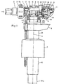
- the waste set 1 shown in Fig. 1 is not in one here used cistern and serves this after a Fill the rinse again with rinse water.
- On a connection nipple 2 the inlet valve to a supply line, not shown here connected.
- This inlet nipple 2 is with a nut 3 attached to a housing 4.
- the plastic one Housing 4 produced by injection molding has one Water channel 14 on that of the connecting nipple 2 to one Membrane valve 26 leads.
- the diaphragm valve 26 When the diaphragm valve 26 is open, it flows the water tangentially into a through a nozzle-shaped extension 15 Ring channel 10 and through a passage opening 22 (Fig. 2nd and 4) into a drain pipe 29. The water enters at the lower end 29a and flows into the cistern, not shown here.
- the diaphragm valve 26 is designed as known per se. It has a membrane 27 made of rubber-elastic material on, which connects the water duct 14 with a chamber 25.
- the chamber 25 has a passage 12 with a Closure body 11 of an actuating lever 5 can be closed is. If the passage 12 shown in Fig. 1 is open, the Pressure in the chamber 25 is significantly lower than that in the water guide channel 14. The membrane 27 is due to this pressure difference lifted off the valve seat 28 and the water can flow into the annular channel 10 from the water channel 14.
- the ring channel 10 is excepted by the disc-shaped insert 17 a passage opening 22 closed.
- This insert is 17 2 and 4 shown in detail.
- This insert is 17 a separately manufactured injection molded part and according to FIG. 1 a radially projecting collar 20 between the upper end 29b and a shoulder 4a of the valve housing 1 clamped. 2 to 4 show, is on the top 24 of the insert 17 a non-circular and approximately kidney-shaped extension 18 is formed, the one corresponding and somewhat eccentrically arranged Passage 19 forms.
- This approach 18 is tubular Approach 16 of the housing 4 used and forms tubular with this Approach 16 a passage 9 that the interior 29c of the Drain pipe 29 connects to the ambient atmosphere.
- insert 17 is positioned so that the passage opening 22 with respect to the tangential inflow direction (Arrow 33) is arranged.
- the edge 20 is on one horizontally extending wall 31 formed, according to 4 to form the passage opening 22 in the form of a ring section is excluded.
- the passage opening 22 extends as can be seen only over a range of the scope, namely how visible by less than 180 ° and a little more than 90 °.
- the Recess, which forms the passage opening 22, can be seen open to the outside.
- the passage opening 22 is dimensioned so that in the Ring channel 10 forms a certain backwater. This has the effect that with the diaphragm valve 26 open, in the passage channel 15 forms a pressure reduction and an air seal. This dampens the noise when the water flows into the Ring channel 10. Since the rotary or spiral movement of the Water is generated in the ring channel 10, there is the function of Insert 17 now only in the throttling of the outlet and in the formation of a back pressure in the annular chamber 10 at the valve outlet. On a comparatively complex multi-course and spiral channel can be dispensed with.
Landscapes
- Engineering & Computer Science (AREA)
- General Engineering & Computer Science (AREA)
- Mechanical Engineering (AREA)
- Public Health (AREA)
- Life Sciences & Earth Sciences (AREA)
- Hydrology & Water Resources (AREA)
- Health & Medical Sciences (AREA)
- Water Supply & Treatment (AREA)
- Details Of Valves (AREA)
- Self-Closing Valves And Venting Or Aerating Valves (AREA)
- Float Valves (AREA)
- Sanitary Device For Flush Toilet (AREA)
- Steam Or Hot-Water Central Heating Systems (AREA)
Description
- Fig. 1
- eine teilweise geschnittene Ansicht einer erfindungsgemässen Einlaufgarnitur,
- Fig. 2
- eine Ansicht eines Einsatzes,
- Fig. 3
- ein Schnitt durch den Einsatz gemäss der Linie III-III der Fig. 4 und
- Fig. 4
- eine Draufsicht auf den Einsatz.
Claims (11)
- Einlaufgarnitur für einen Spülkasten, mit einem Ventilgehäuse (4), das einen Wasserführungskanal (14) aufweist, der von einem an eine Wasserversorgungsleitung anzuschliessenden Einlass (2) zu einem schwimmergesteuerten Membranventil (26) führt, das in einer Membran (27) einen Durchgang (36) für den Druckausgleich zwischen einem Raum (14) vor der Membran (27) und einem Raum (25) nach der Membran (27) aufweist und mit einem nach der Membran (27) angeordneten Ringkanal (10), in den das Wasser bei Gebrauch bei offenem Membranventil (26) tangential einströmt und in dem das Wasser um die Achse (A) eines Ablaufrohres (29) der Einlaufgarnitur rotiert, wobei der Strömungsquerschnitt nach diesem Ringkanal(10) vermindert ist, dadurch gekennzeichnet, dass ein scheibenförmiger in das Ventilgehause (4) eingelegter Einsatz (17) eine untere Wandung des Ringkanals (10) bildet, die mit Ausnahme einer Durchtrittsöffnung (22) den Ringkanal (10) unten abschliesst, derart, dass das im Ringkanal (10) bei gebrauch in Rotation versetzte Wasser durch die Durchtrittsöffnung (22) in das Ablaufrohr (29) strömt, wobei der Einsatz (17) einen Strömungswiderstand bildet, der zu einem geräuschmindernden Luftabschluss führt.
- Einlaufgarnitur nach Anspruch 1, dadurch gekennzeichnet, dass der Einsatz (17) zwischen dem oberen Ende (29b) des Ablaufrohres (29) und dem Ventilgehäuse (4) angeordnet ist.
- Einlaufgarnitur nach Anspruch 1 oder 2, dadurch gekennzeichnet, dass der Einsatz (17) konzentrisch auf das obere Ende (29b) des Ablaufrohres (29) aufgesetzt ist.
- Einlaufgarnitur nach einem der Ansprüche 1 bis 3, dadurch gekennzeichnet, dass der Einsatz (17) einen wenigstens, teilweise umlaufenden und radial vorstehenden Kragen (20) aufweist und dass er an diesem Kragen (20) zwischen dem Ablaufrohr (29) und dem Ventilgehäuse (4) festgeklemmt und positioniert ist.
- Einlaufgarnitur nach einem der Ansprüche 1 bis 4, dadurch gekennzeichnet, dass die Durchtrittsöffnung (22) parallel zur Einströmrichtung angeordnet ist.
- Einlaufgarnitur nach Anspruch 5, dadurch gekennzeichnet, dass die Durchtrittsöffnung (22) etwa nierenförmig ausgebildet ist und sich um weniger als die Hälfte des Umfangs erstreckt.
- Einlaufgarnitur nach einem der Ansprüche 1 bis 6, dadurch gekennzeichnet, dass die Durchtrittsöffnung (22) wenigstens eine sich in Umfangsrichtung erstreckende und schräg nach unten gerichtete Leitfläche (23, 32) aufweist.
- Einlaufgarnitur nach Anspruch 7, dadurch gekennzeichnet, dass sich wenigstens eine Leitfläche (23, 32) um weniger als die Hälfte und vorzugsweise um etwa einen Viertel des Umfanges des Einsatzes (17) erstreckt.
- Einlaufgarnitur nach einem der Ansprüche 1 bis 8, dadurch gekennzeichnet, dass die Durchtrittsöffnung (22) so bemessen ist, dass im Ringkanal (10) bei durchströmendem Wasser ein Rückstau gebildet wird.
- Einlaufgarnitur nach einem der Ansprüche 1 bis 9, dadurch gekennzeichnet, dass der Einsatz (17) eine Entlüftungsöffnung (19) aufweist.
- Einlaufgarnitur nach Anspruch 10, dadurch gekennzeichnet, dass die Entlüftungsöffnung (19) oberhalb einer oberen Fläche (24) einen rohrförmigen unrunden Ansatz (18) aufweist, der von unten in einen rohrförmigen Ansatz (16) des Ventilgehäuses (4) eingreift und dass die beiden genannten rohrförmigen Ansätze (18, 16) einen Verbindungskanal (9) zwischen dem Innenraum (29c) des Ablaufrohres (29) und der Umgebungsatmosphäre bilden.
Applications Claiming Priority (3)
| Application Number | Priority Date | Filing Date | Title |
|---|---|---|---|
| CH123600 | 2000-06-22 | ||
| CH12362000 | 2000-06-22 | ||
| PCT/CH2001/000359 WO2001098592A1 (de) | 2000-06-22 | 2001-06-08 | Einlaufgarnitur für einen spülkasten |
Publications (2)
| Publication Number | Publication Date |
|---|---|
| EP1292736A1 EP1292736A1 (de) | 2003-03-19 |
| EP1292736B1 true EP1292736B1 (de) | 2004-10-27 |
Family
ID=4564425
Family Applications (1)
| Application Number | Title | Priority Date | Filing Date |
|---|---|---|---|
| EP20010935905 Expired - Lifetime EP1292736B1 (de) | 2000-06-22 | 2001-06-08 | Einlaufgarnitur für einen spülkasten |
Country Status (8)
| Country | Link |
|---|---|
| EP (1) | EP1292736B1 (de) |
| AT (2) | AT5284U1 (de) |
| AU (1) | AU6199501A (de) |
| DE (2) | DE20104731U1 (de) |
| DK (1) | DK1292736T3 (de) |
| ES (1) | ES2231496T3 (de) |
| PT (1) | PT1292736E (de) |
| WO (1) | WO2001098592A1 (de) |
Families Citing this family (11)
| Publication number | Priority date | Publication date | Assignee | Title |
|---|---|---|---|---|
| US6755209B2 (en) * | 2002-06-13 | 2004-06-29 | Geberit Technik Ag | Fill valve assembly for a flush tank |
| RU2280804C2 (ru) * | 2004-11-18 | 2006-07-27 | Закрытое акционерное общество "УКЛАД" (ЗАО "УКЛАД") | Наполнительный клапан |
| RU2280803C2 (ru) * | 2004-11-18 | 2006-07-27 | Закрытое акционерное общество "УКЛАД" (ЗАО "УКЛАД") | Клапан |
| CN102345315B (zh) * | 2011-07-15 | 2014-04-30 | 厦门立业卫浴工业有限公司 | 一种多功能进水阀 |
| ES2436649B1 (es) * | 2012-06-28 | 2014-08-07 | Roca Sanitario, S. A. | Dispositivo de carga y descarga para inodoros |
| RU2557817C1 (ru) * | 2014-10-21 | 2015-07-27 | Общество с ограниченной ответственностью "ИнкоЭр" | Поплавковый наполнительный клапан |
| RU2606002C1 (ru) * | 2015-09-18 | 2017-01-10 | Общество с ограниченной ответственностью "ИнкоЭр" | Поплавковый наполнительный клапан |
| EP3263781B1 (de) | 2016-07-01 | 2020-09-23 | Geberit International AG | Einlaufgarnitur |
| IT201900015869A1 (it) | 2019-09-09 | 2019-12-09 | Fazio Vincenzo De | Sistema per la trasmissione del moto in sistemi di carico di liquidi in contenitori |
| FR3141707B1 (fr) * | 2022-11-04 | 2024-10-25 | Siamp Cedap Reunies | Système d’amenée d’eau dans un réservoir de chasse d’eau |
| EP4698728A1 (de) | 2023-04-17 | 2026-02-25 | Geberit International AG | Fitting |
Family Cites Families (8)
| Publication number | Priority date | Publication date | Assignee | Title |
|---|---|---|---|---|
| US3211172A (en) * | 1959-07-27 | 1965-10-12 | American Radiator & Standard | Closet tank fittings |
| CH408804A (de) * | 1963-04-24 | 1966-02-28 | Karl Schwab Gmbh | Spülkasten |
| CH649336A5 (de) * | 1980-10-27 | 1985-05-15 | Geberit Ag | Schwimmerventil zur steuerung des wassereinlaufs in einen toiletten-spuelkasten. |
| US4338964A (en) * | 1980-12-29 | 1982-07-13 | Adolf Schoepe | Side inlet ballcock having flow and structural improvements |
| CH661080A5 (de) | 1983-09-29 | 1987-06-30 | Geberit Ag | Einlaufventil fuer einen toiletten-spuelkasten. |
| NZ239324A (en) | 1990-08-09 | 1993-03-26 | Caroma Ind Ltd | Hydraulically assisted inlet valve for flushing cistern |
| DE19508258A1 (de) | 1995-03-08 | 1996-09-12 | Rost & Co Gmbh | WC-Spülkasten-Füllventil |
| US6354326B1 (en) | 1998-09-14 | 2002-03-12 | Fluidmaster, Inc. | Toilet fill valve with improved noise abatement |
-
2001
- 2001-03-20 DE DE20104731U patent/DE20104731U1/de not_active Expired - Lifetime
- 2001-04-04 AT AT0026301U patent/AT5284U1/de not_active IP Right Cessation
- 2001-06-08 ES ES01935905T patent/ES2231496T3/es not_active Expired - Lifetime
- 2001-06-08 EP EP20010935905 patent/EP1292736B1/de not_active Expired - Lifetime
- 2001-06-08 AU AU61995/01A patent/AU6199501A/en not_active Abandoned
- 2001-06-08 DE DE50104305T patent/DE50104305D1/de not_active Expired - Fee Related
- 2001-06-08 AT AT01935905T patent/ATE280868T1/de not_active IP Right Cessation
- 2001-06-08 WO PCT/CH2001/000359 patent/WO2001098592A1/de not_active Ceased
- 2001-06-08 DK DK01935905T patent/DK1292736T3/da active
- 2001-06-08 PT PT01935905T patent/PT1292736E/pt unknown
Also Published As
| Publication number | Publication date |
|---|---|
| WO2001098592A1 (de) | 2001-12-27 |
| PT1292736E (pt) | 2005-03-31 |
| EP1292736A1 (de) | 2003-03-19 |
| DE50104305D1 (de) | 2004-12-02 |
| DE20104731U1 (de) | 2001-06-21 |
| DK1292736T3 (da) | 2005-02-14 |
| ES2231496T3 (es) | 2005-05-16 |
| AU6199501A (en) | 2002-01-02 |
| AT5284U1 (de) | 2002-05-27 |
| ATE280868T1 (de) | 2004-11-15 |
Similar Documents
| Publication | Publication Date | Title |
|---|---|---|
| EP0731230B1 (de) | WC-Spülkasten-Füllventil | |
| DE2150825C3 (de) | Geräuscharmer Wasserhahn | |
| DE3150100C2 (de) | Schwimmergesteuertes Wasserzulaufventil | |
| EP1292736B1 (de) | Einlaufgarnitur für einen spülkasten | |
| EP2453065B1 (de) | Ablaufgarnitur mit verdeckt positionierbarem Überlauf | |
| EP1371787B1 (de) | Einlaufgarnitur für einen Spülkasten | |
| EP3276095B1 (de) | Vorrichtung zum drosseln des spülstroms aus einem sanitären spülkasten, ablaufventil und sanitärer spülkasten mit einer solchen vorrichtung | |
| DE102015016737A1 (de) | Ablaufgarnitur für einen Spülkasten | |
| DE3201040A1 (de) | Einlassventil fuer einen klosettspuelkasten o.dgl. fluessigkeitsreservoir | |
| DE68916913T2 (de) | Füllventil für einen Toiletten-Spülkasten. | |
| EP3344820A1 (de) | Ablaufventil für wc-spüleinheit, drossel für ablaufventil, spülkasten mit ablaufventil und verfahren zu dessen montage | |
| DE202017104365U1 (de) | Druckminderer-Filter-Anordnung | |
| DE3639285C2 (de) | Bodenablauf | |
| DE2227715C3 (de) | Geräuscharmer Wasserhahn | |
| DE69914626T2 (de) | Ventil | |
| DE2241763A1 (de) | Einlaufgarnitur fuer spuelkaesten | |
| DE20007839U1 (de) | Einlaufgarnitur für einen Spülkasten | |
| DE102007025823B4 (de) | Einbauventil, insbesondere für einen Gliederheizkörper, und Gliederheizkörper | |
| EP3945177B1 (de) | Wasserablauf-einrichtung | |
| DE2522426C3 (de) | Rückstau-Doppelverschluli | |
| EP0962600A2 (de) | Ablaufgarnitur für einen Spülkasten | |
| EP0757135A1 (de) | Spülkasten | |
| EP1066481A1 (de) | Schwimmerventil zum befüllen eines spülkastens | |
| DE3400552C2 (de) | ||
| EP2105540B1 (de) | Servogesteuertes Wasserventil |
Legal Events
| Date | Code | Title | Description |
|---|---|---|---|
| PUAI | Public reference made under article 153(3) epc to a published international application that has entered the european phase |
Free format text: ORIGINAL CODE: 0009012 |
|
| 17P | Request for examination filed |
Effective date: 20020214 |
|
| AK | Designated contracting states |
Kind code of ref document: A1 Designated state(s): AT BE CH CY DE DK ES FI FR GB GR IE IT LI LU MC NL PT SE TR |
|
| AX | Request for extension of the european patent |
Extension state: AL LT LV MK RO SI |
|
| GRAP | Despatch of communication of intention to grant a patent |
Free format text: ORIGINAL CODE: EPIDOSNIGR1 |
|
| GRAS | Grant fee paid |
Free format text: ORIGINAL CODE: EPIDOSNIGR3 |
|
| GRAA | (expected) grant |
Free format text: ORIGINAL CODE: 0009210 |
|
| AK | Designated contracting states |
Kind code of ref document: B1 Designated state(s): AT BE CH CY DE DK ES FI FR GB GR IE IT LI LU MC NL PT SE TR |
|
| PG25 | Lapsed in a contracting state [announced via postgrant information from national office to epo] |
Ref country code: TR Free format text: LAPSE BECAUSE OF FAILURE TO SUBMIT A TRANSLATION OF THE DESCRIPTION OR TO PAY THE FEE WITHIN THE PRESCRIBED TIME-LIMIT Effective date: 20041027 Ref country code: FI Free format text: LAPSE BECAUSE OF FAILURE TO SUBMIT A TRANSLATION OF THE DESCRIPTION OR TO PAY THE FEE WITHIN THE PRESCRIBED TIME-LIMIT Effective date: 20041027 Ref country code: IE Free format text: LAPSE BECAUSE OF FAILURE TO SUBMIT A TRANSLATION OF THE DESCRIPTION OR TO PAY THE FEE WITHIN THE PRESCRIBED TIME-LIMIT Effective date: 20041027 |
|
| REG | Reference to a national code |
Ref country code: GB Ref legal event code: FG4D Free format text: NOT ENGLISH |
|
| REG | Reference to a national code |
Ref country code: CH Ref legal event code: NV Representative=s name: ISLER & PEDRAZZINI AG Ref country code: CH Ref legal event code: EP |
|
| REG | Reference to a national code |
Ref country code: IE Ref legal event code: FG4D Free format text: GERMAN |
|
| REF | Corresponds to: |
Ref document number: 50104305 Country of ref document: DE Date of ref document: 20041202 Kind code of ref document: P |
|
| PG25 | Lapsed in a contracting state [announced via postgrant information from national office to epo] |
Ref country code: SE Free format text: LAPSE BECAUSE OF FAILURE TO SUBMIT A TRANSLATION OF THE DESCRIPTION OR TO PAY THE FEE WITHIN THE PRESCRIBED TIME-LIMIT Effective date: 20050127 Ref country code: GR Free format text: LAPSE BECAUSE OF FAILURE TO SUBMIT A TRANSLATION OF THE DESCRIPTION OR TO PAY THE FEE WITHIN THE PRESCRIBED TIME-LIMIT Effective date: 20050127 |
|
| GBT | Gb: translation of ep patent filed (gb section 77(6)(a)/1977) |
Effective date: 20050117 |
|
| REG | Reference to a national code |
Ref country code: DK Ref legal event code: T3 |
|
| REG | Reference to a national code |
Ref country code: PT Ref legal event code: SC4A Free format text: AVAILABILITY OF NATIONAL TRANSLATION Effective date: 20050125 |
|
| LTIE | Lt: invalidation of european patent or patent extension |
Effective date: 20041027 |
|
| REG | Reference to a national code |
Ref country code: ES Ref legal event code: FG2A Ref document number: 2231496 Country of ref document: ES Kind code of ref document: T3 |
|
| REG | Reference to a national code |
Ref country code: IE Ref legal event code: FD4D |
|
| PG25 | Lapsed in a contracting state [announced via postgrant information from national office to epo] |
Ref country code: LU Free format text: LAPSE BECAUSE OF NON-PAYMENT OF DUE FEES Effective date: 20050608 Ref country code: CY Free format text: LAPSE BECAUSE OF FAILURE TO SUBMIT A TRANSLATION OF THE DESCRIPTION OR TO PAY THE FEE WITHIN THE PRESCRIBED TIME-LIMIT Effective date: 20050608 |
|
| PG25 | Lapsed in a contracting state [announced via postgrant information from national office to epo] |
Ref country code: MC Free format text: LAPSE BECAUSE OF NON-PAYMENT OF DUE FEES Effective date: 20050630 |
|
| PLBE | No opposition filed within time limit |
Free format text: ORIGINAL CODE: 0009261 |
|
| STAA | Information on the status of an ep patent application or granted ep patent |
Free format text: STATUS: NO OPPOSITION FILED WITHIN TIME LIMIT |
|
| 26N | No opposition filed |
Effective date: 20050728 |
|
| ET | Fr: translation filed | ||
| REG | Reference to a national code |
Ref country code: CH Ref legal event code: PCAR Free format text: ISLER & PEDRAZZINI AG;POSTFACH 1772;8027 ZUERICH (CH) |
|
| PGFP | Annual fee paid to national office [announced via postgrant information from national office to epo] |
Ref country code: DK Payment date: 20090611 Year of fee payment: 9 Ref country code: ES Payment date: 20090624 Year of fee payment: 9 Ref country code: NL Payment date: 20090616 Year of fee payment: 9 |
|
| PGFP | Annual fee paid to national office [announced via postgrant information from national office to epo] |
Ref country code: AT Payment date: 20090615 Year of fee payment: 9 Ref country code: FR Payment date: 20090615 Year of fee payment: 9 Ref country code: IT Payment date: 20090626 Year of fee payment: 9 Ref country code: PT Payment date: 20090601 Year of fee payment: 9 |
|
| PGFP | Annual fee paid to national office [announced via postgrant information from national office to epo] |
Ref country code: CH Payment date: 20090420 Year of fee payment: 9 |
|
| PGFP | Annual fee paid to national office [announced via postgrant information from national office to epo] |
Ref country code: DE Payment date: 20090622 Year of fee payment: 9 Ref country code: GB Payment date: 20090618 Year of fee payment: 9 |
|
| PGFP | Annual fee paid to national office [announced via postgrant information from national office to epo] |
Ref country code: BE Payment date: 20090715 Year of fee payment: 9 |
|
| REG | Reference to a national code |
Ref country code: PT Ref legal event code: MM4A Free format text: LAPSE DUE TO NON-PAYMENT OF FEES Effective date: 20101209 |
|
| BERE | Be: lapsed |
Owner name: *GEBERIT TECHNIK A.G. Effective date: 20100630 |
|
| REG | Reference to a national code |
Ref country code: NL Ref legal event code: V1 Effective date: 20110101 |
|
| REG | Reference to a national code |
Ref country code: CH Ref legal event code: PL Ref country code: DK Ref legal event code: EBP |
|
| GBPC | Gb: european patent ceased through non-payment of renewal fee |
Effective date: 20100608 |
|
| PG25 | Lapsed in a contracting state [announced via postgrant information from national office to epo] |
Ref country code: PT Free format text: LAPSE BECAUSE OF NON-PAYMENT OF DUE FEES Effective date: 20101209 |
|
| REG | Reference to a national code |
Ref country code: FR Ref legal event code: ST Effective date: 20110228 |
|
| PG25 | Lapsed in a contracting state [announced via postgrant information from national office to epo] |
Ref country code: IT Free format text: LAPSE BECAUSE OF NON-PAYMENT OF DUE FEES Effective date: 20100608 |
|
| PG25 | Lapsed in a contracting state [announced via postgrant information from national office to epo] |
Ref country code: DE Free format text: LAPSE BECAUSE OF NON-PAYMENT OF DUE FEES Effective date: 20110101 Ref country code: LI Free format text: LAPSE BECAUSE OF NON-PAYMENT OF DUE FEES Effective date: 20100630 Ref country code: CH Free format text: LAPSE BECAUSE OF NON-PAYMENT OF DUE FEES Effective date: 20100630 |
|
| PG25 | Lapsed in a contracting state [announced via postgrant information from national office to epo] |
Ref country code: AT Free format text: LAPSE BECAUSE OF NON-PAYMENT OF DUE FEES Effective date: 20100608 Ref country code: NL Free format text: LAPSE BECAUSE OF NON-PAYMENT OF DUE FEES Effective date: 20110101 Ref country code: FR Free format text: LAPSE BECAUSE OF NON-PAYMENT OF DUE FEES Effective date: 20100630 |
|
| PG25 | Lapsed in a contracting state [announced via postgrant information from national office to epo] |
Ref country code: BE Free format text: LAPSE BECAUSE OF NON-PAYMENT OF DUE FEES Effective date: 20100630 |
|
| REG | Reference to a national code |
Ref country code: ES Ref legal event code: FD2A Effective date: 20110714 |
|
| PG25 | Lapsed in a contracting state [announced via postgrant information from national office to epo] |
Ref country code: GB Free format text: LAPSE BECAUSE OF NON-PAYMENT OF DUE FEES Effective date: 20100608 Ref country code: ES Free format text: LAPSE BECAUSE OF NON-PAYMENT OF DUE FEES Effective date: 20110704 |
|
| PG25 | Lapsed in a contracting state [announced via postgrant information from national office to epo] |
Ref country code: DK Free format text: LAPSE BECAUSE OF NON-PAYMENT OF DUE FEES Effective date: 20100630 |
|
| PG25 | Lapsed in a contracting state [announced via postgrant information from national office to epo] |
Ref country code: ES Free format text: LAPSE BECAUSE OF NON-PAYMENT OF DUE FEES Effective date: 20100609 |