EP1291472A1 - Im Falzraum einer Fassade oder eines Lichtdaches festlegbare Haltevorrichtung - Google Patents
Im Falzraum einer Fassade oder eines Lichtdaches festlegbare Haltevorrichtung Download PDFInfo
- Publication number
- EP1291472A1 EP1291472A1 EP02018478A EP02018478A EP1291472A1 EP 1291472 A1 EP1291472 A1 EP 1291472A1 EP 02018478 A EP02018478 A EP 02018478A EP 02018478 A EP02018478 A EP 02018478A EP 1291472 A1 EP1291472 A1 EP 1291472A1
- Authority
- EP
- European Patent Office
- Prior art keywords
- holding device
- holding
- legs
- profile
- profile strip
- Prior art date
- Legal status (The legal status is an assumption and is not a legal conclusion. Google has not performed a legal analysis and makes no representation as to the accuracy of the status listed.)
- Granted
Links
- 239000011521 glass Substances 0.000 claims description 19
- 229910001220 stainless steel Inorganic materials 0.000 claims description 2
- 239000010935 stainless steel Substances 0.000 claims description 2
- 239000000945 filler Substances 0.000 claims 1
- 239000012212 insulator Substances 0.000 description 2
- 208000027418 Wounds and injury Diseases 0.000 description 1
- 238000004873 anchoring Methods 0.000 description 1
- 238000005452 bending Methods 0.000 description 1
- 230000005540 biological transmission Effects 0.000 description 1
- 238000010276 construction Methods 0.000 description 1
- 230000006378 damage Effects 0.000 description 1
- 208000014674 injury Diseases 0.000 description 1
- 238000003780 insertion Methods 0.000 description 1
- 230000037431 insertion Effects 0.000 description 1
- 239000002184 metal Substances 0.000 description 1
- 238000000034 method Methods 0.000 description 1
- 230000003014 reinforcing effect Effects 0.000 description 1
Images

Classifications
-
- E—FIXED CONSTRUCTIONS
- E04—BUILDING
- E04B—GENERAL BUILDING CONSTRUCTIONS; WALLS, e.g. PARTITIONS; ROOFS; FLOORS; CEILINGS; INSULATION OR OTHER PROTECTION OF BUILDINGS
- E04B2/00—Walls, e.g. partitions, for buildings; Wall construction with regard to insulation; Connections specially adapted to walls
- E04B2/88—Curtain walls
- E04B2/96—Curtain walls comprising panels attached to the structure through mullions or transoms
- E04B2/967—Details of the cross-section of the mullions or transoms
-
- E—FIXED CONSTRUCTIONS
- E04—BUILDING
- E04D—ROOF COVERINGS; SKY-LIGHTS; GUTTERS; ROOF-WORKING TOOLS
- E04D3/00—Roof covering by making use of flat or curved slabs or stiff sheets
- E04D3/02—Roof covering by making use of flat or curved slabs or stiff sheets of plane slabs, slates, or sheets, or in which the cross-section is unimportant
- E04D3/06—Roof covering by making use of flat or curved slabs or stiff sheets of plane slabs, slates, or sheets, or in which the cross-section is unimportant of glass or other translucent material; Fixing means therefor
- E04D3/08—Roof covering by making use of flat or curved slabs or stiff sheets of plane slabs, slates, or sheets, or in which the cross-section is unimportant of glass or other translucent material; Fixing means therefor with metal glazing bars
-
- E—FIXED CONSTRUCTIONS
- E04—BUILDING
- E04D—ROOF COVERINGS; SKY-LIGHTS; GUTTERS; ROOF-WORKING TOOLS
- E04D3/00—Roof covering by making use of flat or curved slabs or stiff sheets
- E04D3/02—Roof covering by making use of flat or curved slabs or stiff sheets of plane slabs, slates, or sheets, or in which the cross-section is unimportant
- E04D3/06—Roof covering by making use of flat or curved slabs or stiff sheets of plane slabs, slates, or sheets, or in which the cross-section is unimportant of glass or other translucent material; Fixing means therefor
- E04D3/08—Roof covering by making use of flat or curved slabs or stiff sheets of plane slabs, slates, or sheets, or in which the cross-section is unimportant of glass or other translucent material; Fixing means therefor with metal glazing bars
- E04D2003/0843—Clamping of the sheets or glass panes to the glazing bars by means of covering strips
Definitions
- the present invention relates to a in the rebate of a facade or one Canopy fixable fixture as pre-assembly element for glass panes or infill panels, the side edges of which on seals of mullion and transom profiles abut, the mullion and transom profiles extending into the rebate have single or multi-part profile strips, which in the area of the outer Free longitudinal edge are provided with a groove open to the outside and the profile bar fixable holding device has at least one holding leg, which supports an outer surface of the glass pane or filling plate.
- DE 200 15 646 describes a holding device for a transom-and-facade known in which an adapter element on the profile bar of a mullion or transom profile is mounted. Retaining clips made of metal with a are on the adapter element first leg lockable with a second leg on a glass pane or fill plate and lay it on a post or transom.
- the disadvantage of this holding device is that it consists of at least two components, namely the adapter and the bracket clip.
- a retaining clip for glass panes or Filling plates which can be inserted into an outwardly open groove of a profile strip is.
- the bracket has an opening and can therefore be on the profile bar be screwed to the mullion or transom profile.
- After inserting the Holding clips grip the anchoring webs for pre-fixing in the undercut Groove the profile bar.
- the disadvantage here is that the grooves of profile strips for not always have corresponding undercuts and thus the retaining clip is not mountable on every profile strip, and partly also very small grooves are provided so that the insertion of the retaining clip itself difficult designed.
- one in the rebate space of a facade or a light roof fixable holding device of the type mentioned create that in a simple way with a certain tolerance compensation on one Profile bar of a transom-post construction can be pre-fixed.
- the holding device has legs that by means of clamping forces on the Profile bar can be determined, the holding device can easily on the Profile bar can be pre-assembled without a separate for the pre-assembly Tool is required. Furthermore, the holding device can be used flexibly since the Legs for applying the clamping forces have an elasticity and thus the Shape of the profile bar can vary within a certain tolerance range. The Legs can be inside the profile bar as well as outside on the profile bar attack.
- the holding device can be plugged onto the profile strip and can therefore be installed particularly quickly.
- the legs grip the profile strip in a U-shape, so that the Groove of the profile bar can be used for other purposes.
- the legs can protrude outwards Have end sections so that the end sections do not get caught on the profile strip and the legs spread apart when attached to the profile strip can be.
- the legs preferably extend outside the end sections facing each other, so that the holding device is already relatively thin Profile strips is mountable.
- tolerances of the profile strips can be special be well balanced.
- the holding device preferably comprises a central opening for passage a screw in the groove of the profile strip. So that the holding device can be easily be securely attached to the transom or post profile.
- the at least one holding leg is inclined from the outside inwards runs to the glass pane or filling plate and an outwardly bent end section is provided, on the one hand, tolerances due to different thicknesses Glass or infill panels are balanced and still the necessary Holding forces are applied. Through the end sections bent outwards it is ensured that not a sharp end edge to rest on the Glass pane or filling plate comes.
- a screw head is preferably accommodated between two holding legs, which are molded onto a central part.
- the screw head is not inferior outside, which reduces the risk of injury and looks more appealing.
- the holding device has only a small height and can be easily be covered by a strip attached above the rebate area.
- an edge between the middle part and Retaining leg transverse embossments may be provided.
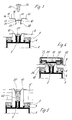
- a holding device punched out of a stainless steel sheet and manufactured using the bending process 10 comprises a rectangular central part 11, which is at least attached to Connect holding leg 12 on one side. If only one holding leg 12 is provided is, the holding device is used to attach glass panes or panels on the end of facades or skylights. In the present case two holding legs 12 are provided, and the holding device 10 is one Center plane formed symmetrically.
- An upstanding section 13 of the holding leg extends from the middle part 11 upwards and is then in a substantially horizontal section 14 bent.
- This section 14 is closed at an angle downwards extending portion 15, which in turn to an upwardly bent end portion 16 adjacent.
- the terms "above” and “below” refer to the in Fig. 3 shown assembled state and can also be interchanged depending on the position of the profile become.
- legs 20 which run obliquely inwards in a section 21 and at an end section 22 protrude outwards.
- recesses 23 are formed on the central part 11, the direct power transmission between the legs 20 and the holding legs Avoid 12.
- a holding device 10 is before assembly and on a locking profile 1 shown.
- the locking profile 1 comprises a profile strip 2, on the an outwardly open groove 3 is provided. Both sides of the profile bar 2 are Grooves 4 are formed on the locking profile 1, into which seals 5 are drawn. A glass pane 6 bears against these seals 5.
- the holding device 10 is first plugged onto the profile bar 2, wherein the legs 20 are clamped against the profile bar 2. Through the Legs 20 running obliquely inwards can have profile strips of different thicknesses 2 between the elastic legs 20 are added.
- a screw 25 screwed through the opening 17 into the groove 3 of the profile strip 2.
- the holding legs 12 using a certain elasticity against the glass panes 6 pressed and fix them via the seals 5 on the transom profile 1.
- the Screw 25 is received with its head 26 between the holding legs 12 and does not protrude beyond them.
- the holding device 10 needs due to the flat Training for final assembly can no longer be removed.
- a holding profile 30 via screws 31 fixed to the profile bar 2 the holding profile 30 via seals 32 abuts the glass pane 6.
- the seal presses in the area of the holding leg 12 32 on the holding leg 12 and encloses this due to its elasticity.
- a cover profile 33 is then attached for a closed appearance the holding profile 30 locked.
- the holding device 10 is attached to an insulator 40 which in a Groove 3 of a profile strip 2 of the locking profile 1 is fixed. Through the isolator 40 the distance of the holding device 10 to the locking profile 1 increases, and it thicker panels, such as insulating glass panes 6 ', are used.
- the holding device 10 can on a longer screw 25 'on the groove 3 or directly the insulator 40 can be set. In this case, the profile strip is made up of several parts.
Landscapes
- Engineering & Computer Science (AREA)
- Architecture (AREA)
- Civil Engineering (AREA)
- Structural Engineering (AREA)
- Physics & Mathematics (AREA)
- Electromagnetism (AREA)
- Securing Of Glass Panes Or The Like (AREA)
- Load-Bearing And Curtain Walls (AREA)
- Joining Of Building Structures In Genera (AREA)
- Clamps And Clips (AREA)
Abstract
Description
- Fig. 1
- eine perspektivische Ansicht eines Ausführungsbeispieles einer erfindungsgemäßen Haltevorrichtung;
- Fig. 2
- eine perspektivische Ansicht der Haltevorrichtung bei der Montage;
- Fig. 3
- eine Seitenansicht der Haltevorrichtung der Fig. 1 bei der Montage;
- Fig. 4
- eine Seitenansicht der Haltevorrichtung der Fig. 1 im montierten Zustand, und
- Fig. 5
- eine Seitenansicht einer Haltevorrichtung an einer leicht modifizierten Profilleiste.
Claims (11)
- Im Falzraum einer Fassade oder eines Lichtdaches festlegbare Haltevorrichtung (10) als Vormontageelement für Glasscheiben (6, 6') oder Füllungsplatten, deren Seitenränder an Dichtungen (5) von Pfosten- und Riegelprofilen (1) anliegen, wobei die Pfosten- und Riegelprofile (1) sich in den Falzraum erstreckende ein- oder mehrteilige Profilleisten (2) aufweisen, die im Bereich des äußeren freien Längsrandes mit einer nach außen geöffneten Nut (3) versehen sind und die an der Profilleiste (2) festlegbare Haltevorrichtung (10) mindestens einen Halteschenkel (12) aufweist, der eine Außenfläche der Glasscheibe (6) oder Füllungsplatte abstützt, dadurch gekennzeichnet, dass die Haltevorrichtung (10) Schenkel (20) aufweist, die mittels Klemmkräften an der Profilleiste (2) festlegbar sind.
- Haltevorrichtung nach Anspruch 1, dadurch gekennzeichnet, dass die Haltevorrichtung (10) auf die Profilleiste (2) aufsteckbar ist.
- Haltevorrichtung nach Anspruch 1 oder 2, dadurch gekennzeichnet, dass die Schenkel (20) die Profilleisten (2) U-förmig umgreifen.
- Haltevorrichtung nach Anspruch 3, dadurch gekennzeichnet, dass die Schenkel (20) nach außen abstehende Endabschnitte (22) aufweisen.
- Haltevorrichtung nach Anspruch 3 oder 4, dadurch gekennzeichnet, dass die Schenkel (20) zueinander gerichtet verlaufen.
- Haltevorrichtung nach einem der Ansprüche 1 bis 5, dadurch gekennzeichnet, dass die Haltevorrichtung (10) eine mittige Öffnung (17) zur Durchführung einer Schraube (25) in die Nut (3) der Profilleiste (2) aufweist.
- Haltevorrichtung nach einem der Ansprüche 1 bis 6, dadurch gekennzeichnet, dass der mindestens eine Halteschenkel (12) von einer Außenseite schräg nach innen zu der Glasscheibe (6, 6') oder Füllungsplatte verläuft und ein nach außen gebogener Endabschnitt (16) vorgesehen ist.
- Haltevorrichtung nach einem der Ansprüche 1 bis 7, dadurch gekennzeichnet, dass die Haltevorrichtung (10) einen Mittelteil (11) aufweist, von dem sich zwei Halteschenkel (12) zunächst nach außen und dann zu der Glasscheibe (6) oder Füllungsplatte erstrecken und ein Schraubkopf (26) zwischen den Halteschenkeln (12) aufgenommen ist.
- Haltevorrichtung nach einem der Ansprüche 1 bis 8, dadurch gekennzeichnet, dass an einer Kante (18) zwischen Mittelteil (11) und Halteschenkel (12) Querprägungen (19) vorgesehen sind.
- Haltevorrichtung nach einem der Ansprüche 1 bis 9, dadurch gekennzeichnet, dass das Mittelteil (11) der Haltevorrichtung (10) die Nut (3) der Profilleiste (2) abdeckt, in einem mittleren Bereich die Halteschenkel (12) und endseitig jeweils die an der Profilleiste (2) festlegbaren Schenkel (20) vorgesehen sind.
- Haltevorrichtung nach einem der Ansprüche 1 bis 10, dadurch gekennzeichnet, dass die Haltevorrichtung (10) aus einem gestanzten und gebogenen Edelstahlblech hergestellt ist.
Applications Claiming Priority (2)
| Application Number | Priority Date | Filing Date | Title |
|---|---|---|---|
| DE20114225U | 2001-08-29 | ||
| DE20114225U DE20114225U1 (de) | 2001-08-29 | 2001-08-29 | Im Falzraum einer Fassade oder eines Lichtdaches festlegbare Haltevorrichtung |
Publications (2)
| Publication Number | Publication Date |
|---|---|
| EP1291472A1 true EP1291472A1 (de) | 2003-03-12 |
| EP1291472B1 EP1291472B1 (de) | 2007-10-03 |
Family
ID=7961050
Family Applications (1)
| Application Number | Title | Priority Date | Filing Date |
|---|---|---|---|
| EP02018478A Expired - Lifetime EP1291472B1 (de) | 2001-08-29 | 2002-08-16 | Im Falzraum einer Fassade oder eines Lichtdaches festlegbare Haltevorrichtung |
Country Status (3)
| Country | Link |
|---|---|
| EP (1) | EP1291472B1 (de) |
| AT (1) | ATE374873T1 (de) |
| DE (2) | DE20114225U1 (de) |
Cited By (1)
| Publication number | Priority date | Publication date | Assignee | Title |
|---|---|---|---|---|
| CN112031224A (zh) * | 2020-09-10 | 2020-12-04 | 广东省第一建筑工程有限公司 | 一种幕墙、具有该幕墙的墙体及一种幕墙的安装方法 |
Families Citing this family (1)
| Publication number | Priority date | Publication date | Assignee | Title |
|---|---|---|---|---|
| US8919070B2 (en) | 2012-08-30 | 2014-12-30 | Technoform Holding GmbH | Spacer for retaining cladding element on structural building element |
Citations (5)
| Publication number | Priority date | Publication date | Assignee | Title |
|---|---|---|---|---|
| EP0385218A1 (de) * | 1989-02-27 | 1990-09-05 | Herbert Lacker | Rahmenkonstruktion |
| CH675743A5 (en) * | 1988-01-15 | 1990-10-31 | Arnold Eggenberger Metallbaupl | Cladding profile for facade or roof - has mounting portion fixed in holder, in turn, secured to support tube |
| GB2307263A (en) * | 1995-11-15 | 1997-05-21 | Peter Anthony Boyce | Panel sealing structure |
| DE19922239A1 (de) * | 1999-05-14 | 2000-11-16 | Schueco Int Kg | Halteklammer für Glasscheiben oder Füllungsplatten einer Fassade oder eines Lichtdaches |
| DE20015646U1 (de) * | 2000-09-09 | 2000-11-30 | Schüco International KG, 33609 Bielefeld | Haltevorrichtung für eine Riegel-Pfosten-Fassade |
-
2001
- 2001-08-29 DE DE20114225U patent/DE20114225U1/de not_active Expired - Lifetime
-
2002
- 2002-08-16 AT AT02018478T patent/ATE374873T1/de active
- 2002-08-16 EP EP02018478A patent/EP1291472B1/de not_active Expired - Lifetime
- 2002-08-16 DE DE50211001T patent/DE50211001D1/de not_active Expired - Lifetime
Patent Citations (5)
| Publication number | Priority date | Publication date | Assignee | Title |
|---|---|---|---|---|
| CH675743A5 (en) * | 1988-01-15 | 1990-10-31 | Arnold Eggenberger Metallbaupl | Cladding profile for facade or roof - has mounting portion fixed in holder, in turn, secured to support tube |
| EP0385218A1 (de) * | 1989-02-27 | 1990-09-05 | Herbert Lacker | Rahmenkonstruktion |
| GB2307263A (en) * | 1995-11-15 | 1997-05-21 | Peter Anthony Boyce | Panel sealing structure |
| DE19922239A1 (de) * | 1999-05-14 | 2000-11-16 | Schueco Int Kg | Halteklammer für Glasscheiben oder Füllungsplatten einer Fassade oder eines Lichtdaches |
| DE20015646U1 (de) * | 2000-09-09 | 2000-11-30 | Schüco International KG, 33609 Bielefeld | Haltevorrichtung für eine Riegel-Pfosten-Fassade |
Cited By (2)
| Publication number | Priority date | Publication date | Assignee | Title |
|---|---|---|---|---|
| CN112031224A (zh) * | 2020-09-10 | 2020-12-04 | 广东省第一建筑工程有限公司 | 一种幕墙、具有该幕墙的墙体及一种幕墙的安装方法 |
| CN112031224B (zh) * | 2020-09-10 | 2022-07-19 | 广东省第一建筑工程有限公司 | 一种幕墙、具有该幕墙的墙体及一种幕墙的安装方法 |
Also Published As
| Publication number | Publication date |
|---|---|
| DE20114225U1 (de) | 2001-10-31 |
| EP1291472B1 (de) | 2007-10-03 |
| DE50211001D1 (de) | 2007-11-15 |
| ATE374873T1 (de) | 2007-10-15 |
Similar Documents
| Publication | Publication Date | Title |
|---|---|---|
| EP0501994B1 (de) | Verbindungsformstück für bauprofile | |
| EP3477012B1 (de) | Haltevorrichtung zur befestigung einer brüstungs- oder geländerplatte | |
| DE20100747U1 (de) | Riegel/Pfosten-Konstruktion | |
| DE202017104559U1 (de) | Mechanisch gesichertes Frontprofil für einen französischen Balkon | |
| DE19707564B4 (de) | Montagesystem zur Halterung von Verkleidungselementen an Bauwerken | |
| EP1580344B1 (de) | Stossverbinder zum winkeligen Verbinden von Hohlprofilen, insbesondere für Fenster, Türen und dergleichen | |
| DE2443098A1 (de) | Anordnung zur befestigung eines verkleidungsprofiles | |
| DE19758464C2 (de) | Isolierelement aus wenigstens zwei Glas- oder Kunststoffscheiben und mit Profilschienen oder -teilen zur Montage in einem Rahmen | |
| EP0067970B1 (de) | Befestigungsvorrichtung für Fassadenelemente an einer Gebäudeaussenwand | |
| EP1291472B1 (de) | Im Falzraum einer Fassade oder eines Lichtdaches festlegbare Haltevorrichtung | |
| DE19808847C2 (de) | Tür- oder Fensterbeschlag | |
| EP0524631B1 (de) | Halteglied für Isolierglasscheiben | |
| AT407418B (de) | Verkleidung für fenster und türen | |
| EP2060728A2 (de) | Glashalteleiste, Rahmenkonstruktion sowie Verfahren zur Montage einer Glashalteleiste | |
| EP1262625A2 (de) | Thermisch getrennte Regenschutzschiene oder Bodenschwelle | |
| DE2334802A1 (de) | Halteeinrichtung fuer die scheiben bei druckverglasung an fenstern oder tueren aus metall, holz oder kunststoff | |
| DE4027335C2 (de) | ||
| DE10154058A1 (de) | Holz-Alu-Fenster | |
| EP0722033B1 (de) | Eckpfosten für eine Wandverkleidung aus mit einem Kunststoffrahmen versehenen Verkleidungselementen | |
| DE202007019257U1 (de) | Glashalteleiste, Rahmenkonstruktion | |
| DE69002041T2 (de) | Montagesystem und montageelemente für trennwände in bürogebäuden und dergleichen. | |
| DE19742744C1 (de) | Holzrahmen für eine Tür oder ein Fenster mit integrierter Glasscheibe | |
| DE4438026C1 (de) | Trennwand für Duschen | |
| DE202019003306U1 (de) | Halteprofil und System zur Halterung | |
| EP3859096B1 (de) | Befestigungsprofil und installationsanordnung zum festlegen eines brüstungselements |
Legal Events
| Date | Code | Title | Description |
|---|---|---|---|
| PUAI | Public reference made under article 153(3) epc to a published international application that has entered the european phase |
Free format text: ORIGINAL CODE: 0009012 |
|
| AK | Designated contracting states |
Kind code of ref document: A1 Designated state(s): AT BE BG CH CY CZ DE DK EE ES FI FR GB GR IE IT LI LU MC NL PT SE SK TR |
|
| AX | Request for extension of the european patent |
Extension state: AL LT LV MK RO SI |
|
| 17P | Request for examination filed |
Effective date: 20030819 |
|
| AKX | Designation fees paid |
Designated state(s): AT BE BG CH CY CZ DE DK EE ES FI FR GB GR IE IT LI LU MC NL PT SE SK TR |
|
| GRAP | Despatch of communication of intention to grant a patent |
Free format text: ORIGINAL CODE: EPIDOSNIGR1 |
|
| GRAS | Grant fee paid |
Free format text: ORIGINAL CODE: EPIDOSNIGR3 |
|
| GRAA | (expected) grant |
Free format text: ORIGINAL CODE: 0009210 |
|
| AK | Designated contracting states |
Kind code of ref document: B1 Designated state(s): AT BE BG CH CY CZ DE DK EE ES FI FR GB GR IE IT LI LU MC NL PT SE SK TR |
|
| REG | Reference to a national code |
Ref country code: GB Ref legal event code: FG4D Free format text: NOT ENGLISH |
|
| REG | Reference to a national code |
Ref country code: CH Ref legal event code: EP |
|
| REG | Reference to a national code |
Ref country code: IE Ref legal event code: FG4D Free format text: LANGUAGE OF EP DOCUMENT: GERMAN |
|
| REF | Corresponds to: |
Ref document number: 50211001 Country of ref document: DE Date of ref document: 20071115 Kind code of ref document: P |
|
| REG | Reference to a national code |
Ref country code: CH Ref legal event code: NV Representative=s name: KATZAROV S.A. |
|
| GBV | Gb: ep patent (uk) treated as always having been void in accordance with gb section 77(7)/1977 [no translation filed] | ||
| PG25 | Lapsed in a contracting state [announced via postgrant information from national office to epo] |
Ref country code: ES Free format text: LAPSE BECAUSE OF FAILURE TO SUBMIT A TRANSLATION OF THE DESCRIPTION OR TO PAY THE FEE WITHIN THE PRESCRIBED TIME-LIMIT Effective date: 20080114 Ref country code: SE Free format text: LAPSE BECAUSE OF FAILURE TO SUBMIT A TRANSLATION OF THE DESCRIPTION OR TO PAY THE FEE WITHIN THE PRESCRIBED TIME-LIMIT Effective date: 20080103 |
|
| PG25 | Lapsed in a contracting state [announced via postgrant information from national office to epo] |
Ref country code: PT Free format text: LAPSE BECAUSE OF FAILURE TO SUBMIT A TRANSLATION OF THE DESCRIPTION OR TO PAY THE FEE WITHIN THE PRESCRIBED TIME-LIMIT Effective date: 20080303 Ref country code: BG Free format text: LAPSE BECAUSE OF FAILURE TO SUBMIT A TRANSLATION OF THE DESCRIPTION OR TO PAY THE FEE WITHIN THE PRESCRIBED TIME-LIMIT Effective date: 20080103 |
|
| REG | Reference to a national code |
Ref country code: IE Ref legal event code: FD4D |
|
| EN | Fr: translation not filed | ||
| PG25 | Lapsed in a contracting state [announced via postgrant information from national office to epo] |
Ref country code: CZ Free format text: LAPSE BECAUSE OF FAILURE TO SUBMIT A TRANSLATION OF THE DESCRIPTION OR TO PAY THE FEE WITHIN THE PRESCRIBED TIME-LIMIT Effective date: 20071003 Ref country code: DK Free format text: LAPSE BECAUSE OF FAILURE TO SUBMIT A TRANSLATION OF THE DESCRIPTION OR TO PAY THE FEE WITHIN THE PRESCRIBED TIME-LIMIT Effective date: 20071003 |
|
| PLBE | No opposition filed within time limit |
Free format text: ORIGINAL CODE: 0009261 |
|
| STAA | Information on the status of an ep patent application or granted ep patent |
Free format text: STATUS: NO OPPOSITION FILED WITHIN TIME LIMIT |
|
| PG25 | Lapsed in a contracting state [announced via postgrant information from national office to epo] |
Ref country code: SK Free format text: LAPSE BECAUSE OF FAILURE TO SUBMIT A TRANSLATION OF THE DESCRIPTION OR TO PAY THE FEE WITHIN THE PRESCRIBED TIME-LIMIT Effective date: 20071003 |
|
| 26N | No opposition filed |
Effective date: 20080704 |
|
| PG25 | Lapsed in a contracting state [announced via postgrant information from national office to epo] |
Ref country code: IE Free format text: LAPSE BECAUSE OF FAILURE TO SUBMIT A TRANSLATION OF THE DESCRIPTION OR TO PAY THE FEE WITHIN THE PRESCRIBED TIME-LIMIT Effective date: 20071003 Ref country code: FR Free format text: LAPSE BECAUSE OF FAILURE TO SUBMIT A TRANSLATION OF THE DESCRIPTION OR TO PAY THE FEE WITHIN THE PRESCRIBED TIME-LIMIT Effective date: 20080704 |
|
| PGFP | Annual fee paid to national office [announced via postgrant information from national office to epo] |
Ref country code: LU Payment date: 20080826 Year of fee payment: 7 |
|
| PG25 | Lapsed in a contracting state [announced via postgrant information from national office to epo] |
Ref country code: GB Free format text: LAPSE BECAUSE OF FAILURE TO SUBMIT A TRANSLATION OF THE DESCRIPTION OR TO PAY THE FEE WITHIN THE PRESCRIBED TIME-LIMIT Effective date: 20071003 |
|
| PG25 | Lapsed in a contracting state [announced via postgrant information from national office to epo] |
Ref country code: GR Free format text: LAPSE BECAUSE OF FAILURE TO SUBMIT A TRANSLATION OF THE DESCRIPTION OR TO PAY THE FEE WITHIN THE PRESCRIBED TIME-LIMIT Effective date: 20080104 |
|
| PG25 | Lapsed in a contracting state [announced via postgrant information from national office to epo] |
Ref country code: MC Free format text: LAPSE BECAUSE OF NON-PAYMENT OF DUE FEES Effective date: 20080831 |
|
| PG25 | Lapsed in a contracting state [announced via postgrant information from national office to epo] |
Ref country code: EE Free format text: LAPSE BECAUSE OF FAILURE TO SUBMIT A TRANSLATION OF THE DESCRIPTION OR TO PAY THE FEE WITHIN THE PRESCRIBED TIME-LIMIT Effective date: 20071003 |
|
| PG25 | Lapsed in a contracting state [announced via postgrant information from national office to epo] |
Ref country code: CY Free format text: LAPSE BECAUSE OF FAILURE TO SUBMIT A TRANSLATION OF THE DESCRIPTION OR TO PAY THE FEE WITHIN THE PRESCRIBED TIME-LIMIT Effective date: 20071003 |
|
| PGFP | Annual fee paid to national office [announced via postgrant information from national office to epo] |
Ref country code: NL Payment date: 20090820 Year of fee payment: 8 |
|
| PG25 | Lapsed in a contracting state [announced via postgrant information from national office to epo] |
Ref country code: FI Free format text: LAPSE BECAUSE OF FAILURE TO SUBMIT A TRANSLATION OF THE DESCRIPTION OR TO PAY THE FEE WITHIN THE PRESCRIBED TIME-LIMIT Effective date: 20071003 |
|
| PGFP | Annual fee paid to national office [announced via postgrant information from national office to epo] |
Ref country code: BE Payment date: 20090821 Year of fee payment: 8 |
|
| PG25 | Lapsed in a contracting state [announced via postgrant information from national office to epo] |
Ref country code: TR Free format text: LAPSE BECAUSE OF FAILURE TO SUBMIT A TRANSLATION OF THE DESCRIPTION OR TO PAY THE FEE WITHIN THE PRESCRIBED TIME-LIMIT Effective date: 20071003 |
|
| PGFP | Annual fee paid to national office [announced via postgrant information from national office to epo] |
Ref country code: CH Payment date: 20100825 Year of fee payment: 9 |
|
| PGFP | Annual fee paid to national office [announced via postgrant information from national office to epo] |
Ref country code: AT Payment date: 20100820 Year of fee payment: 9 |
|
| BERE | Be: lapsed |
Owner name: SCHUCO INTERNATIONAL K.G. Effective date: 20100831 |
|
| PG25 | Lapsed in a contracting state [announced via postgrant information from national office to epo] |
Ref country code: IT Free format text: LAPSE BECAUSE OF NON-PAYMENT OF DUE FEES Effective date: 20080831 |
|
| REG | Reference to a national code |
Ref country code: NL Ref legal event code: V1 Effective date: 20110301 |
|
| PG25 | Lapsed in a contracting state [announced via postgrant information from national office to epo] |
Ref country code: LU Free format text: LAPSE BECAUSE OF NON-PAYMENT OF DUE FEES Effective date: 20090816 |
|
| PG25 | Lapsed in a contracting state [announced via postgrant information from national office to epo] |
Ref country code: NL Free format text: LAPSE BECAUSE OF NON-PAYMENT OF DUE FEES Effective date: 20110301 |
|
| PG25 | Lapsed in a contracting state [announced via postgrant information from national office to epo] |
Ref country code: BE Free format text: LAPSE BECAUSE OF NON-PAYMENT OF DUE FEES Effective date: 20100831 |
|
| REG | Reference to a national code |
Ref country code: CH Ref legal event code: PL |
|
| PG25 | Lapsed in a contracting state [announced via postgrant information from national office to epo] |
Ref country code: LI Free format text: LAPSE BECAUSE OF NON-PAYMENT OF DUE FEES Effective date: 20110831 Ref country code: CH Free format text: LAPSE BECAUSE OF NON-PAYMENT OF DUE FEES Effective date: 20110831 |
|
| REG | Reference to a national code |
Ref country code: AT Ref legal event code: MM01 Ref document number: 374873 Country of ref document: AT Kind code of ref document: T Effective date: 20110816 |
|
| PG25 | Lapsed in a contracting state [announced via postgrant information from national office to epo] |
Ref country code: AT Free format text: LAPSE BECAUSE OF NON-PAYMENT OF DUE FEES Effective date: 20110816 |
|
| PGFP | Annual fee paid to national office [announced via postgrant information from national office to epo] |
Ref country code: DE Payment date: 20160819 Year of fee payment: 15 |
|
| REG | Reference to a national code |
Ref country code: DE Ref legal event code: R119 Ref document number: 50211001 Country of ref document: DE |
|
| PG25 | Lapsed in a contracting state [announced via postgrant information from national office to epo] |
Ref country code: DE Free format text: LAPSE BECAUSE OF NON-PAYMENT OF DUE FEES Effective date: 20180301 |