EP1291214A2 - Rahmen für ein Fahrzeug-Schiebedach oder-Schiebehebedach - Google Patents
Rahmen für ein Fahrzeug-Schiebedach oder-Schiebehebedach Download PDFInfo
- Publication number
- EP1291214A2 EP1291214A2 EP02014384A EP02014384A EP1291214A2 EP 1291214 A2 EP1291214 A2 EP 1291214A2 EP 02014384 A EP02014384 A EP 02014384A EP 02014384 A EP02014384 A EP 02014384A EP 1291214 A2 EP1291214 A2 EP 1291214A2
- Authority
- EP
- European Patent Office
- Prior art keywords
- front part
- holding plate
- motor holding
- frame according
- channels
- Prior art date
- Legal status (The legal status is an assumption and is not a legal conclusion. Google has not performed a legal analysis and makes no representation as to the accuracy of the status listed.)
- Granted
Links
- 239000002991 molded plastic Substances 0.000 claims abstract description 5
- 239000004033 plastic Substances 0.000 claims description 16
- 229920003023 plastic Polymers 0.000 claims description 16
- 238000002347 injection Methods 0.000 claims description 11
- 239000007924 injection Substances 0.000 claims description 11
- 238000007789 sealing Methods 0.000 claims description 10
- 239000000565 sealant Substances 0.000 claims description 6
- 230000007704 transition Effects 0.000 claims description 5
- 229920000049 Carbon (fiber) Polymers 0.000 claims description 2
- 238000005299 abrasion Methods 0.000 claims description 2
- 239000004917 carbon fiber Substances 0.000 claims description 2
- 230000007423 decrease Effects 0.000 claims 1
- 238000005553 drilling Methods 0.000 description 6
- XLYOFNOQVPJJNP-UHFFFAOYSA-N water Substances O XLYOFNOQVPJJNP-UHFFFAOYSA-N 0.000 description 3
- 239000003292 glue Substances 0.000 description 2
- 238000009434 installation Methods 0.000 description 2
- 238000004519 manufacturing process Methods 0.000 description 2
- 229910000838 Al alloy Inorganic materials 0.000 description 1
- 239000000853 adhesive Substances 0.000 description 1
- 230000001070 adhesive effect Effects 0.000 description 1
- XAGFODPZIPBFFR-UHFFFAOYSA-N aluminium Chemical compound [Al] XAGFODPZIPBFFR-UHFFFAOYSA-N 0.000 description 1
- 229910052782 aluminium Inorganic materials 0.000 description 1
- 239000002131 composite material Substances 0.000 description 1
- 238000010276 construction Methods 0.000 description 1
- 230000003247 decreasing effect Effects 0.000 description 1
- 238000006073 displacement reaction Methods 0.000 description 1
- 238000004049 embossing Methods 0.000 description 1
- 238000003780 insertion Methods 0.000 description 1
- 230000037431 insertion Effects 0.000 description 1
- 239000007788 liquid Substances 0.000 description 1
- VNWKTOKETHGBQD-UHFFFAOYSA-N methane Chemical compound C VNWKTOKETHGBQD-UHFFFAOYSA-N 0.000 description 1
- 238000000465 moulding Methods 0.000 description 1
- 238000003825 pressing Methods 0.000 description 1
- 238000007493 shaping process Methods 0.000 description 1
- 230000001629 suppression Effects 0.000 description 1
- 238000010792 warming Methods 0.000 description 1
Images




Classifications
-
- B—PERFORMING OPERATIONS; TRANSPORTING
- B60—VEHICLES IN GENERAL
- B60J—WINDOWS, WINDSCREENS, NON-FIXED ROOFS, DOORS, OR SIMILAR DEVICES FOR VEHICLES; REMOVABLE EXTERNAL PROTECTIVE COVERINGS SPECIALLY ADAPTED FOR VEHICLES
- B60J7/00—Non-fixed roofs; Roofs with movable panels, e.g. rotary sunroofs
- B60J7/02—Non-fixed roofs; Roofs with movable panels, e.g. rotary sunroofs of sliding type, e.g. comprising guide shoes
- B60J7/022—Sliding roof trays or assemblies
Definitions
- the invention relates to one of several parts composite frame for a vehicle sunroof or Sliding roof, according to the preamble of the claim 1.
- the invention has for its object a framework provide training specified at the outset, which is inexpensive and manufacture and assemble from a few parts leaves.
- Different frames require the standard motor mounting plate only one also standardized Recess.
- the shaping of the open cable ducts enables an easier insertion of the drive cables in the front part and the waiver of additional items to be manufactured and attached Guide tubes.
- the cover elements for the cable ducts are also inexpensive plastic injection molded parts to be produced. They form according to theirs Installation on the front part with its inner surfaces, contact and guide surfaces for the drive cables inserted in the cable ducts.
- the feedthrough channels are preferably in the motor holding plate here designed as stated in claim 3, i.e. have their narrowest cross-section at the point of attack between the drive cables and the drive pinion.
- the suppression of noise during drive movements the drive cable also serve the specified in claim 3 Transitional chamfers or roundings.
- the motor mounting plate and the front part can be made accordingly Claim 5 with locking elements for pre-locking during assembly the frame and the engine.
- the cover elements can be on the front part of the frame accordingly Claim 8 by a combination of clip elements and screw connections. This opens up the advantageous Possibility of the cover elements when installing the First clip the frame with the front part before the a fixed connection is made.
- Here can be inserted through openings in the cover elements Screw directly into the plastic of the front part and / or screwed threaded bushings injected into the front part become.
- connection of the side parts with the front part to the frame in a mutually exactly positioned position and the attachment these parts of the frame to each other is useful by the measures specified in claims 9 and 10 achieved, without embossing the side parts.
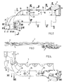
- Fig. 1 The individual parts of the frame are shown in Fig. 1. shown are the broken drawn front part 1 with the in the direction of travel on the left-hand corner area 2 (the right-hand side Corner area is mirrored, e.g. from Fig. 8 emerges), the broken area superimposed on the corner area 2 left side part 3 (the right side part is a mirror image), the left cover element 4 (the approximately mirror-image right cover element 5 goes out Fig. 7), the motor holding plate 6 and the electric gear motor 7th
- the front part 1, the cover elements 4, 5 and the engine mounting plate 6 are injection molded from suitable plastics, whereby for the individual parts depending on the stress different plastics can be used. So can the motor mounting plate 6 made of a plastic with a higher Strength, especially a higher abrasion resistance than the other parts.
- the one for the engine mounting plate 6 plastic used can also be carbon fiber be armored.
- the plastic injection molded parts in a suitable manner for Increased stiffness can be ribbed, which also makes it proportionate small wall thicknesses are made possible.
- the motor holding plate 6 has two spaced apart Axially parallel bushings 12, of which in Fig. 17th only one is shown and that in FIG visible channel openings are indicated. After installation the motor holding plate 6 in the recess 10 of the front part 1 the feed-through channels 12 are continuously aligned the cable ducts 11. Starting from a central recess 13 in the motor holding plate 6 for the schematic in Fig. 16 Drive pinions 14 shown are opposite passage openings (not shown) in the wall areas the motor holding plate 6 between the feedthrough channels 12 and the central recess 13 provided for the permanent Engagement of the drive pinion 14 with the drive cables are used. The drive cables stand with the movable cover of the roof structure in drive connection.
- the drive pinion 14 has an external toothing with which it is connected to the two drive cables stands in a rack-like tooth mesh.
- the motor 7 can drive the pinion 14 optionally in one or drive the other direction of rotation, whereby each opposite Sliding movements of the two drive cables caused become.
- the feed-through channels 12 one from the channel ends to the point of engagement with the Drive pinion 14 steadily decreasing circular cross-section on at its narrowest point only by a play greater than is the outer diameter of the drive cable. This will ensured that the drive cable under the influence of the Tooth pressure can not avoid the pinion, but from the relevant wall areas of the feed-through channels 12 be supported.
- the feed-through channels 12 are in each case provide transition bevels or roundings at both ends, as indicated in Fig. 17. Similar transition phases or - Roundings are at the adjacent entrances or exits of the cable ducts 11 and also on the adjacent edges of the Cover elements 4.5 are provided.
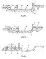
- the motor mounting plate 6 and the front part 1 are in the area the recess 10 for the motor mounting plate 6 with locking elements 18 for pre-locking the motor mounting plate 6 on the front part 1 equipped, as Fig. 16 illustrates.
- Fig. 16 illustrates.
- the motor 7 with the Front part 1 with the interposition of the motor holding plate 6 on several Places screwed like the example of one of these places 16 is shown in FIG.
- the cover elements 4.5 are on the front part 1 by a Combination of spaced-apart clip elements and Screws attached.
- the clip elements include protrusions 22 and associated receiving slots 23, such as. B. from Fig. 2 emerges in connection with Fig. 15.
- the screw connection points 24 can be seen, for example, from FIGS. 2 and 4.
- the side parts 3 are from above on the corner regions 2 of the front part 1 placed, with molded on the front part 1 positioning projections 25 with attached in the side parts 3 Positioning openings 26 engage to the exact desired Relative position of side parts 3 and front part 1, as can be seen from FIGS. 2 and 10.
- fastener ensure a firm connection of these parts 1, 3.
- fasteners are screws in the example shown (not shown) through holes 27 in the side parts 3 screwed into the front part 1 or its corner areas 2 are (Fig. 2, 14), and on the other hand through holes 28 of the side parts 3 thermoniet protrusions 29 the corner areas 2 (Fig. 2, 10) are provided.
- By warming and Applying pressure to the thermal rivet projections 29 deforms them and riveted in the holes 28.
- Both the front part 1 and the side parts 3 are in the in such a frame usual way with open to the top communicating water channels 30 and 31, as can be seen, for example, from FIGS. 11 and 13.
- the water that accumulates in the water channels 30, 31 becomes Via pipe sockets 32 (e.g. Fig. 1) dissipated.
- pipe sockets 32 e.g. Fig. 1
- a sealing channel 33 is formed in each front part / corner region is, as is apparent from Fig. 8 in connection with Fig. 13.
- These sealing channels 33 are initially liquid Sealant or glue can be filled.
- the sealant / glue can through holes 34 in the side parts 3 through the sealing channels 33 are supplied, as shown in FIG. 13.
- the sealant or adhesive completely fills the sealing channels and lies close to all of the sealing channels delimiting wall surfaces.
- a frame for vehicle roofs of all usual is proposed Types such as sunroofs, sunroofs and top-first sunroofs (Spoiler roofs), with preferred motor drive for those using a cable drive system relative to one Roof opening movable cover.
- the only composed of a few parts Frame includes an injection molded plastic Front part with cable ducts open at the bottom and molded on Corner areas for the fixed attachment of the lid on guide rails leading frame side parts, which are preferred are cut to length from extruded aluminum profiles.
- the cable ducts open at the bottom, into which the drive cables can be easily inserted by at least a cover element also injection molded from plastic is closed.
- a motor mounting plate is made of plastic injection molded part is provided so that it consists of a other plastic specially adapted to the drive requirements can be shaped with high dimensional accuracy.
- the frame can be produced inexpensively and by molding Assemble assembly and positioning aids quickly and easily. By standardizing its few parts, in particular the motor mounting plate, the frame can be different vehicle-specific requirements can be adapted inexpensively.
Landscapes
- Engineering & Computer Science (AREA)
- Mechanical Engineering (AREA)
- Injection Moulding Of Plastics Or The Like (AREA)
- Vehicle Interior And Exterior Ornaments, Soundproofing, And Insulation (AREA)
- Power-Operated Mechanisms For Wings (AREA)
- Body Structure For Vehicles (AREA)
- Seal Device For Vehicle (AREA)
Abstract
Description
- Fig. 1
- eine explosionsbildartige perspektivische Darstellung der in Fahrtrichtung vorderen linken Ecke des Rahmens, mit abgebrochen gezeigtem Vorderteil und linksseitigem Seitenteil,
- Fig. 2
- die Draufsicht auf die in Fahrtrichtung vordere linke Ecke des abgebrochen gezeigten fertig montierten Rahmens,
- Fig. 3
- die Ansicht des Rahmens von hinten,
- Fig. 4
- die Unteransicht der in Fig. 2 gezeigten Rahmenecke,
- Fig. 5
- die Unteransicht des Vorderteils mit montierten Abdeckelementen, vorverrasteter Motorhalteplatte, noch ohne Motor, und in Fahrtrichtung linksseitigem, abgebrochen dargestelltem Seitenteil,
- Fig. 6
- die Draufsicht auf die in Fig. 6 gezeigte Anordnung,
- Fig. 7
- die Unteransicht des Vorderteils ohne Abdeckelemente und ohne Motorplatte,
- Fig. 8
- die Draufsicht auf das Vorderteil gemäß Fig. 7,
- Fig. 9
- den Schnitt entsprechend der Schnittverlaufslinie IX-IX in Fig. 2,
- Fig. 10
- den Schnitt entsprechend der Schnittverlaufslinie X-X in Fig. 2,
- Fig. 11
- den Schnitt entsprechend der Schnittverlaufslinie XI-XI in Fig. 2,
- Fig. 12
- den Schnitt entsprechend der Schnittverlaufslinie XII-XII in Fig. 2,
- Fig. 13
- den Schnitt entsprechend der Schnittverlaufslinie XIII-XIII in Fig. 2,
- Fig. 14
- den Schnitt entsprechend der Schnittverlaufslinie XIV-XIV in Fig. 2,
- Fig. 15
- den Schnitt entsprechend der Schnittverlaufslinie XV-XV in Fig. 2,
- Fig. 16
- den abgebrochenen Schnitt entlang der Linie XVI-XVI in Fig. 4 und
- Fig. 17
- den abgebrochenen Schnitt entlang der Linie XVII-XVII in Fig. 4.
- 1
- Vorderteil
- 2
- Eckbereich
- 3
- Seitenteil
- 4
- linkes Abdeckelement
- 5
- rechtes Abdeckelement
- 6
- Motorhalteplatte
- 7
- Elektrogetriebemotor
- 8
- Führungsschienen
- 9
- Kabelführungskanäle
- 10
- Ausnehmung
- 11
- Kabelkanäle
- 12
- Durchführungskanäle
- 13
- Zentrale Aussparung
- 14
- Antriebsritzel
- 15
- Positioniervorsprünge
- 16
- Positionieröffnungen
- 17
- Auflageflächen
- 18
- Rastelemente
- 19
- Bohrung
- 20
- Bohrung
- 21
- Bohrung
- 22
- Vorsprünge
- 23
- Aufnahmeschlitze
- 24
- Verschraubungsstellen
- 25
- Positioniervorsprünge
- 26
- Positionieröffnungen
- 27
- Bohrungen
- 28
- Bohrungen
- 29
- Thermonietvorsprünge
- 30
- Wasserkanal
- 31
- Wasserkanal
- 32
- Rohrstutzen
- 33
- Abdichtkanal
- 34
- Bohrungen
Claims (12)
- Aus mehreren Teilen zusammengesetzter Rahmen für ein Fahrzeug-Schiebedach oder -Schiebehebedach zur Führung und Halterung eines einer entsprechenden Dachöffnung zugeordneten bewegbaren Deckels, mit einem als Kunststoffspritzteil ausgebildeten Vorderteil (1) und zwei parallel zueinander angeordneten, Führungsschienen (8) für den Deckel aufweisenden Seitenteilen (3), die mit dem Vorderteil (1) über an dieses angeformte Eckbereiche (2) fest verbindbar sind, wobei am Vorderteil (1), den Eckbereichen (2) und den Seitenteilen (3) Antriebskabel für die Bewegung des Deckels drucksteif verschiebbar geführt sind, die mit einer am Vorderteil (1) über eine Motorhalteplatte (6) angeordneten Antriebsvorrichtung im Antriebseingriff stehen, dadurch gekennzeichnet, daß in das Vorderteil (1) zu beiden Seiten einer für die Aufnahme der als getrenntes Kunststoffspritzteil hergestellten Motorhalteplatte (6) eingeformten Ausnehmung (10) nach unten offene Kabelkanäle (11) für die Antriebskabel eingeformt sind, die durch ebenfalls als Kunststoffspritzteile ausgebildete und am Vorderteil positioniert zu befestigende Abdeckelemente (4, 5) verschließbar sind.
- Rahmen nach Anspruch 1, dadurch gekennzeichnet, daß die Motorhalteplatte (6) zwei voneinander beabstandete parallele Durchführungskanäle (12) für die Antriebskabel aufweist, die nach Anbringung der Motorhalteplatte (6) in der Ausnehmung (10) des Vorderteils (1) mit den Kabelkanälen (11) stufenlos fluchten, und die ausgehend von einer zentralen Aussparung (13) in der Motorhalteplatte (6) für das Antriebsritzel (14) mit gegenüberliegenden Durchtrittsöffnungen für den Eingriff des Antriebsritzels (14) mit beiden Antriebskabeln versehen ist.
- Rahmen nach Anspruch 2, dadurch gekennzeichnet, daß die Durchführungskanäle (12) einen von den Kanalenden her bis zur Eingriffsstelle mit dem Antriebsritzel (14) stetig abnehmenden Kreisquerschnitt aufweisen, und daß die Durchführungskanäle (12) an jeweils beiden Enden mit Übergangsfasen oder -abrundungen versehen sind, denen ähnliche Übergangsfasen oder - abrundungen an den benachbarten Eingängen der Kabelkanäle (11) und an den Abdeckelementen (4, 5) entsprechen.
- Rahmen nach einem der Ansprüche 1 bis 3, dadurch gekennzeichnet, daß die Ausnehmung (10) für die Aufnahme der Motorhalteplatte (6) und die Motorhalteplatte (6) selbst zur genauen Ausrichtung der Durchführungskanäle (12) in der Motorhalteplatte (6) zu den anschließenden Kabelkanälen (11) in dem Vorderteil (1) mit paarweise angeordneten Positioniervorsprüngen (15) und -öffnungen (16) und die Ausnehmung (10) mit mehreren voneinander beabstandeten vorspringenden Auflageflächen (17) für die Motorhalteplatte (6) versehen sind.
- Rahmen nach einem der Ansprüche 1 bis 4, dadurch gekennzeichnet, daß die Motorhalteplatte (6) und das Vorderteil (1) im Bereich der Ausnehmung (10) für die Motorhalteplatte (6) mit Rastelementen (18) für die Vorverrastung der Motorhalteplatte (6) am Vorderteil (1) ausgerüstet sind.
- Rahmen nach einem der Ansprüche 1 bis 5, dadurch gekennzeichnet, daß das Vorderteil (1) und die Motorhalteplatte (6) aus unterschiedlichen Kunststoffen spritzgeformt sind, wobei der für die Motorhalteplatte (6) verwendete Kunststoff vergleichsweise eine höhere Festigkeit, insbesondere eine höhere Abriebfestigkeit aufweist und/oder durch Kohlefasern armiert ist.
- Rahmen nach einem der Ansprüche 1 bis 6, dadurch gekennzeichnet, daß der Motor (7) mit dem Vorderteil (1) unter Zwischenlage der Motorhalteplatte (6) verschraubt ist.
- Rahmen nach einem der Ansprüche 1 bis 7, dadurch gekennzeichnet, daß die Abdeckelemente (4, 5) an dem Vorderteil (1) durch eine Kombination von voneinander beabstandeten Klipselementen (22, 23) und Verschraubungen (24) befestigt sind.
- Rahmen nach einem der Ansprüche 1 bis 8, dadurch gekennzeichnet, daß die Seitenteile (3) auf die Eckbereiche (2) des Vorderteils (1) von oben unter Vermittlung des Eingriffs von an das Vorderteil (1) angeformten Positioniervorsprüngen (25) mit in den Seitenteilen (3) angebrachten entsprechenden Positionieröffnungen (26) positioniert aufgelegt und durch Befestigungsmittel fest miteinander vereinigt sind.
- Rahmen nach Anspruch 9, dadurch gekennzeichnet, daß die Befestigungsmittel durch Bohrungen (27) in den Seitenteilen (3) hindurchgeführte und in das Vorderteil (1) eingeschraubte Schrauben und/oder an das Vorderteil angeformte und durch Bohrungen (28) der Seitenteile (3) geführte Thermonietvorsprünge (29) sind.
- Rahmen nach Anspruch 9 oder 10, dadurch gekennzeichnet, daß in den Auflagebereichen der Seitenteile (3) auf das Vorderteil (1) im Vorderteil jeweils ein Abdichtkanal (33) eingeformt ist, der zur Abdichtung der Seitenteile (3) gegenüber dem Vorderteil (1) in den Auflagebereichen mit einem Dichtmittel befüllbar ist.
- Rahmen nach Anspruch 11, dadurch gekennzeichnet, daß das Dichtmittel durch Bohrungen (34) in den Seitenteilen (3) hindurch den Abdichtkanälen (33) zuführbar ist.
Applications Claiming Priority (2)
| Application Number | Priority Date | Filing Date | Title |
|---|---|---|---|
| DE10144738A DE10144738B4 (de) | 2001-09-11 | 2001-09-11 | Rahmen für ein Fahrzeug-Schiebedach oder -Schiebehebedach |
| DE10144738 | 2001-09-11 |
Publications (3)
| Publication Number | Publication Date |
|---|---|
| EP1291214A2 true EP1291214A2 (de) | 2003-03-12 |
| EP1291214A3 EP1291214A3 (de) | 2004-01-14 |
| EP1291214B1 EP1291214B1 (de) | 2006-09-06 |
Family
ID=7698638
Family Applications (1)
| Application Number | Title | Priority Date | Filing Date |
|---|---|---|---|
| EP02014384A Expired - Lifetime EP1291214B1 (de) | 2001-09-11 | 2002-06-28 | Rahmen für ein Fahrzeug-Schiebedach oder-Schiebehebedach |
Country Status (5)
| Country | Link |
|---|---|
| US (1) | US6663172B2 (de) |
| EP (1) | EP1291214B1 (de) |
| AT (1) | ATE338649T1 (de) |
| DE (2) | DE10144738B4 (de) |
| MX (1) | MXPA02008718A (de) |
Cited By (2)
| Publication number | Priority date | Publication date | Assignee | Title |
|---|---|---|---|---|
| CN110316108A (zh) * | 2018-03-29 | 2019-10-11 | 克龙贝格和舒伯特两合有限公司 | 振动解耦的电缆导引装置 |
| DE102018116227A1 (de) | 2018-07-04 | 2020-01-09 | Roof Systems Germany Gmbh | Mehrteiliger Rahmen für ein Fahrzeug-Schiebedach oder Fahrzeug-Schiebehebedach und Verfahren zur Montage eines mehrteiligen Rahmens |
Families Citing this family (12)
| Publication number | Priority date | Publication date | Assignee | Title |
|---|---|---|---|---|
| DE102005047390B4 (de) * | 2005-10-04 | 2008-01-17 | Webasto Ag | Trägerrahmen, insbesondere für Dachsysteme im Kraftfahrzeugbereich |
| FR2892977A1 (fr) † | 2005-11-07 | 2007-05-11 | Wagon Sas | Cadre d'occultation pour pavillon vitre d'un vehicule automobile, et vehicule correspondant |
| DE102006002006B4 (de) * | 2006-01-16 | 2009-09-10 | Webasto Ag | Antriebsträger für ein öffnungsfähiges Fahrzeugdach |
| DE102006002005B4 (de) * | 2006-01-16 | 2009-12-03 | Webasto Ag | Antriebsträgervorrichtung für ein öffnungsfähiges Fahrzeugdach |
| DE102009052110A1 (de) * | 2009-11-05 | 2011-05-12 | Faurecia Innenraum Systeme Gmbh | Kraftfahrzeug-Frontend |
| US8814259B2 (en) * | 2012-02-20 | 2014-08-26 | Inalfa Roof Systems Group B.V. | Frame for open roof construction |
| DE102013006131A1 (de) * | 2013-04-10 | 2014-10-16 | Webasto SE | Dachrahmenbauteil eines Dachöffnungssystems eines Fahrzeugs |
| US10857860B2 (en) | 2015-12-08 | 2020-12-08 | Steven J Janssen | Sliding roof assembly for sport vehicle |
| DE102016213823A1 (de) * | 2016-07-27 | 2018-02-01 | Bos Gmbh & Co. Kg | Schiebedachsystem eines Kraftfahrzeugs und Führungsschienenprofil hierfür |
| CN107599803A (zh) * | 2017-09-15 | 2018-01-19 | 安徽省地坤汽车天窗科技有限公司 | 一种后置电机的天窗 |
| DE102020133010B4 (de) | 2020-12-10 | 2025-02-06 | Roof Systems Germany Gmbh | Baugruppe eines Dachsystems |
| DE102021114517A1 (de) | 2021-06-07 | 2022-12-08 | Webasto SE | Fahrzeugdach mit einer Rahmenvorrichtung |
Citations (2)
| Publication number | Priority date | Publication date | Assignee | Title |
|---|---|---|---|---|
| DE4014487C1 (de) | 1990-05-07 | 1991-08-14 | Webasto Ag Fahrzeugtechnik, 8035 Stockdorf, De | |
| DE19746545A1 (de) | 1997-10-22 | 1999-05-06 | Webasto Karosseriesysteme | Rahmen für ein Fahrzeugschiebedach |
Family Cites Families (11)
| Publication number | Priority date | Publication date | Assignee | Title |
|---|---|---|---|---|
| DE2836801A1 (de) * | 1978-08-23 | 1980-03-06 | Volkswagenwerk Ag | Verfahren zum zusammenbau eines stahlkurbeldaches fuer ein fahrzeug |
| DE2856015C2 (de) * | 1978-12-23 | 1986-12-04 | Webasto-Werk W. Baier GmbH & Co, 8035 Gauting | Fahrzeugdach |
| US4422687A (en) * | 1980-10-14 | 1983-12-27 | American Sunroof Corporation | Sliding roof panel assembly |
| DE3532104A1 (de) * | 1985-09-09 | 1987-04-23 | Webasto Werk Baier Kg W | Vormontierte einbaueinheit fuer schiebehebedaecher von fahrzeugen |
| USRE34098E (en) * | 1987-08-20 | 1992-10-13 | Webasto Ag Fahrzeugtechnik | Frame arrangement for a vehicle roof |
| NL9101111A (nl) * | 1991-06-27 | 1993-01-18 | Vermeulen Hollandia Octrooien | Open-dakconstructie voor een voertuig. |
| US5612600A (en) * | 1995-10-17 | 1997-03-18 | Webasto Sunroofs Inc. | Position encoder system for a movable panel |
| DE19732700B4 (de) * | 1997-07-30 | 2005-07-14 | Webasto Ag | Rahmenanordnung für ein Deckelteil eines Fahrzeugdaches |
| FR2771970B1 (fr) * | 1997-12-10 | 2000-02-04 | Webasto Systemes Carrosserie | Traverse avant de cadre de toit ouvrant |
| US6065801A (en) * | 1998-05-19 | 2000-05-23 | Yachiyo Kogyo Kabushiki Kaisha | Rear drain channel arrangement for an automotive sunroof |
| US6431644B1 (en) * | 1999-10-29 | 2002-08-13 | Aisin Seiki Kabushiki Kaisha | Sliding roof device |
-
2001
- 2001-09-11 DE DE10144738A patent/DE10144738B4/de not_active Expired - Fee Related
-
2002
- 2002-06-28 AT AT02014384T patent/ATE338649T1/de not_active IP Right Cessation
- 2002-06-28 DE DE50208057T patent/DE50208057D1/de not_active Expired - Lifetime
- 2002-06-28 EP EP02014384A patent/EP1291214B1/de not_active Expired - Lifetime
- 2002-09-06 MX MXPA02008718A patent/MXPA02008718A/es active IP Right Grant
- 2002-09-10 US US10/238,417 patent/US6663172B2/en not_active Expired - Fee Related
Patent Citations (2)
| Publication number | Priority date | Publication date | Assignee | Title |
|---|---|---|---|---|
| DE4014487C1 (de) | 1990-05-07 | 1991-08-14 | Webasto Ag Fahrzeugtechnik, 8035 Stockdorf, De | |
| DE19746545A1 (de) | 1997-10-22 | 1999-05-06 | Webasto Karosseriesysteme | Rahmen für ein Fahrzeugschiebedach |
Cited By (6)
| Publication number | Priority date | Publication date | Assignee | Title |
|---|---|---|---|---|
| CN110316108A (zh) * | 2018-03-29 | 2019-10-11 | 克龙贝格和舒伯特两合有限公司 | 振动解耦的电缆导引装置 |
| CN110316108B (zh) * | 2018-03-29 | 2022-11-25 | 克龙贝格和舒伯特两合有限公司 | 振动解耦的电缆导引装置 |
| DE102018116227A1 (de) | 2018-07-04 | 2020-01-09 | Roof Systems Germany Gmbh | Mehrteiliger Rahmen für ein Fahrzeug-Schiebedach oder Fahrzeug-Schiebehebedach und Verfahren zur Montage eines mehrteiligen Rahmens |
| FR3083485A1 (fr) | 2018-07-04 | 2020-01-10 | Roof Systems Germany Gmbh | Cadre en plusieurs pièces pour un toit coulissant de véhicule ou un toit coulissant/basculant de véhicule et procédé de montage d’un cadre en plusieurs pièces |
| DE102018116227B4 (de) | 2018-07-04 | 2022-12-22 | Roof Systems Germany Gmbh | Mehrteiliger Rahmen für ein Fahrzeug-Schiebedach oder Fahrzeug-Schiebehebedach und Verfahren zur Montage eines mehrteiligen Rahmens |
| US11584204B2 (en) | 2018-07-04 | 2023-02-21 | Roof Systems Germany Gmbh | Multi-part frame for a vehicle sliding sunroof or vehicle sliding and tilting roof and method for assembling a multi-part frame |
Also Published As
| Publication number | Publication date |
|---|---|
| MXPA02008718A (es) | 2004-03-09 |
| DE10144738B4 (de) | 2005-08-11 |
| DE50208057D1 (de) | 2006-10-19 |
| US20030047969A1 (en) | 2003-03-13 |
| DE10144738A1 (de) | 2003-03-27 |
| ATE338649T1 (de) | 2006-09-15 |
| US6663172B2 (en) | 2003-12-16 |
| EP1291214A3 (de) | 2004-01-14 |
| EP1291214B1 (de) | 2006-09-06 |
Similar Documents
| Publication | Publication Date | Title |
|---|---|---|
| DE19838347C2 (de) | Führungsschiene und Verfahren zur Herstellung einer Führungsschiene für einen Seil- oder Bowdenrohr-Fensterheber | |
| EP0455975B1 (de) | Rahmen für ein Fahrzeug-Schiebedach oder -Schiebehebedach | |
| EP0936092B1 (de) | Kraftfahrzeugtür | |
| EP1291214B1 (de) | Rahmen für ein Fahrzeug-Schiebedach oder-Schiebehebedach | |
| EP0214139A1 (de) | Tür aus kunststoff für kraftfahrzeuge. | |
| EP3912864B1 (de) | Vehicle trim strp device and vehicle with such a trim strip device | |
| DE10144742C2 (de) | Rahmen für ein Fahrzeug-Schiebedach oder -Schiebehebedach | |
| EP1522442B1 (de) | Fahrzeugfestes Führungssytem und Verfahren zum Herstellen eines fahrzeugfesten Führungssystems | |
| DE102005033115A1 (de) | Aggregateträger für eine Kraftfahrzeugtür | |
| DE19727010B4 (de) | Fensterrahmenmodul zur Herstellung von Kraftfahrzeugtüren | |
| EP3638524B1 (de) | Dichtungsanordnung zur führung und abdichtung einer vertikal bewegbaren fahrzeugfensterscheibe | |
| EP0888918A2 (de) | Betätigungsanordnung für den Deckel eines Kraftfahrzeugschiebedachs | |
| DE102019213161A1 (de) | Rahmenelement für eine Fensterscheibe, Fensterscheibenanordnung und Fahrzeug | |
| EP1669245A1 (de) | Dachmodul für ein Fahrzeug | |
| DE10116593B4 (de) | Fahrzeugdach | |
| DE29722214U1 (de) | Abdeckkappe für ein Airbagmodul | |
| DE19732700B4 (de) | Rahmenanordnung für ein Deckelteil eines Fahrzeugdaches | |
| EP0593909B1 (de) | Kunststoff-Halteclip für Schutz-, Zierleisten oder dergleichen, insbesondere an Kraftfahrzeugen | |
| DE102021131727A1 (de) | Fahrzeugscheibenanordnung | |
| DE10205118A1 (de) | Führungsanordnung für ein verstellbares Dachelement | |
| DE102004017569A1 (de) | Fahrzeugbauteil mit einer Führungsschienenstruktur | |
| WO1995001492A1 (de) | Seilzug-fensterheber | |
| DE102006014402B4 (de) | Trennwand für eine Kraftwagenkarosserie | |
| EP1827882B1 (de) | Spiegelmodul, insbesondere für ein fahrzeug, komponente, die das spiegelmodul aufweist, komponente, insbesondere sonnenblende und insbesondere für ein fahrzeug, verfahren zur montage des spiegelmoduls, verfahren zur montage der komponente und verwendung der komponente als sonnenblende eines kraftfahrzeugs | |
| DE10340745B3 (de) | Kraftfahrzeug-Dachmodul mit integrierter Befestigungseinrichtung |
Legal Events
| Date | Code | Title | Description |
|---|---|---|---|
| PUAI | Public reference made under article 153(3) epc to a published international application that has entered the european phase |
Free format text: ORIGINAL CODE: 0009012 |
|
| AK | Designated contracting states |
Kind code of ref document: A2 Designated state(s): AT BE CH CY DE DK ES FI FR GB GR IE IT LI LU MC NL PT SE TR Designated state(s): AT BE CH CY DE DK ES FI FR GB GR IE IT LI LU MC NL PT SE TR |
|
| AX | Request for extension of the european patent |
Extension state: AL LT LV MK RO SI |
|
| PUAL | Search report despatched |
Free format text: ORIGINAL CODE: 0009013 |
|
| AK | Designated contracting states |
Kind code of ref document: A3 Designated state(s): AT BE CH CY DE DK ES FI FR GB GR IE IT LI LU MC NL PT SE TR |
|
| AX | Request for extension of the european patent |
Extension state: AL LT LV MK RO SI |
|
| RIC1 | Information provided on ipc code assigned before grant |
Ipc: 7B 60J 7/057 B Ipc: 7B 60J 7/02 A |
|
| 17P | Request for examination filed |
Effective date: 20040131 |
|
| AKX | Designation fees paid |
Designated state(s): AT BE CH CY DE DK ES FI FR GB GR IE IT LI LU MC NL PT SE TR |
|
| GRAP | Despatch of communication of intention to grant a patent |
Free format text: ORIGINAL CODE: EPIDOSNIGR1 |
|
| GRAS | Grant fee paid |
Free format text: ORIGINAL CODE: EPIDOSNIGR3 |
|
| GRAA | (expected) grant |
Free format text: ORIGINAL CODE: 0009210 |
|
| AK | Designated contracting states |
Kind code of ref document: B1 Designated state(s): AT BE CH CY DE DK ES FI FR GB GR IE IT LI LU MC NL PT SE TR |
|
| PG25 | Lapsed in a contracting state [announced via postgrant information from national office to epo] |
Ref country code: IT Free format text: LAPSE BECAUSE OF FAILURE TO SUBMIT A TRANSLATION OF THE DESCRIPTION OR TO PAY THE FEE WITHIN THE PRESCRIBED TIME-LIMIT;WARNING: LAPSES OF ITALIAN PATENTS WITH EFFECTIVE DATE BEFORE 2007 MAY HAVE OCCURRED AT ANY TIME BEFORE 2007. THE CORRECT EFFECTIVE DATE MAY BE DIFFERENT FROM THE ONE RECORDED. Effective date: 20060906 Ref country code: IE Free format text: LAPSE BECAUSE OF FAILURE TO SUBMIT A TRANSLATION OF THE DESCRIPTION OR TO PAY THE FEE WITHIN THE PRESCRIBED TIME-LIMIT Effective date: 20060906 Ref country code: GB Free format text: LAPSE BECAUSE OF FAILURE TO SUBMIT A TRANSLATION OF THE DESCRIPTION OR TO PAY THE FEE WITHIN THE PRESCRIBED TIME-LIMIT Effective date: 20060906 Ref country code: FI Free format text: LAPSE BECAUSE OF FAILURE TO SUBMIT A TRANSLATION OF THE DESCRIPTION OR TO PAY THE FEE WITHIN THE PRESCRIBED TIME-LIMIT Effective date: 20060906 |
|
| REG | Reference to a national code |
Ref country code: GB Ref legal event code: FG4D Free format text: NOT ENGLISH |
|
| REG | Reference to a national code |
Ref country code: CH Ref legal event code: EP |
|
| REG | Reference to a national code |
Ref country code: IE Ref legal event code: FG4D Free format text: LANGUAGE OF EP DOCUMENT: GERMAN |
|
| REF | Corresponds to: |
Ref document number: 50208057 Country of ref document: DE Date of ref document: 20061019 Kind code of ref document: P |
|
| PG25 | Lapsed in a contracting state [announced via postgrant information from national office to epo] |
Ref country code: SE Free format text: LAPSE BECAUSE OF FAILURE TO SUBMIT A TRANSLATION OF THE DESCRIPTION OR TO PAY THE FEE WITHIN THE PRESCRIBED TIME-LIMIT Effective date: 20061206 Ref country code: DK Free format text: LAPSE BECAUSE OF FAILURE TO SUBMIT A TRANSLATION OF THE DESCRIPTION OR TO PAY THE FEE WITHIN THE PRESCRIBED TIME-LIMIT Effective date: 20061206 |
|
| PG25 | Lapsed in a contracting state [announced via postgrant information from national office to epo] |
Ref country code: ES Free format text: LAPSE BECAUSE OF FAILURE TO SUBMIT A TRANSLATION OF THE DESCRIPTION OR TO PAY THE FEE WITHIN THE PRESCRIBED TIME-LIMIT Effective date: 20061217 |
|
| PG25 | Lapsed in a contracting state [announced via postgrant information from national office to epo] |
Ref country code: PT Free format text: LAPSE BECAUSE OF FAILURE TO SUBMIT A TRANSLATION OF THE DESCRIPTION OR TO PAY THE FEE WITHIN THE PRESCRIBED TIME-LIMIT Effective date: 20070219 |
|
| GBV | Gb: ep patent (uk) treated as always having been void in accordance with gb section 77(7)/1977 [no translation filed] |
Effective date: 20060906 |
|
| ET | Fr: translation filed | ||
| REG | Reference to a national code |
Ref country code: IE Ref legal event code: FD4D |
|
| PLBI | Opposition filed |
Free format text: ORIGINAL CODE: 0009260 |
|
| PLAX | Notice of opposition and request to file observation + time limit sent |
Free format text: ORIGINAL CODE: EPIDOSNOBS2 |
|
| 26 | Opposition filed |
Opponent name: WEBASTO AG Effective date: 20070604 |
|
| NLR1 | Nl: opposition has been filed with the epo |
Opponent name: WEBASTO AG |
|
| PLAF | Information modified related to communication of a notice of opposition and request to file observations + time limit |
Free format text: ORIGINAL CODE: EPIDOSCOBS2 |
|
| BERE | Be: lapsed |
Owner name: ARVINMERITOR G.M.B.H. Effective date: 20070630 |
|
| PGFP | Annual fee paid to national office [announced via postgrant information from national office to epo] |
Ref country code: IT Payment date: 20070630 Year of fee payment: 6 |
|
| PG25 | Lapsed in a contracting state [announced via postgrant information from national office to epo] |
Ref country code: MC Free format text: LAPSE BECAUSE OF NON-PAYMENT OF DUE FEES Effective date: 20070630 |
|
| PLBB | Reply of patent proprietor to notice(s) of opposition received |
Free format text: ORIGINAL CODE: EPIDOSNOBS3 |
|
| REG | Reference to a national code |
Ref country code: CH Ref legal event code: PL |
|
| PG25 | Lapsed in a contracting state [announced via postgrant information from national office to epo] |
Ref country code: BE Free format text: LAPSE BECAUSE OF NON-PAYMENT OF DUE FEES Effective date: 20070630 |
|
| PG25 | Lapsed in a contracting state [announced via postgrant information from national office to epo] |
Ref country code: LI Free format text: LAPSE BECAUSE OF NON-PAYMENT OF DUE FEES Effective date: 20070630 Ref country code: GR Free format text: LAPSE BECAUSE OF FAILURE TO SUBMIT A TRANSLATION OF THE DESCRIPTION OR TO PAY THE FEE WITHIN THE PRESCRIBED TIME-LIMIT Effective date: 20061207 Ref country code: CH Free format text: LAPSE BECAUSE OF NON-PAYMENT OF DUE FEES Effective date: 20070630 |
|
| PG25 | Lapsed in a contracting state [announced via postgrant information from national office to epo] |
Ref country code: AT Free format text: LAPSE BECAUSE OF NON-PAYMENT OF DUE FEES Effective date: 20070628 |
|
| PLCK | Communication despatched that opposition was rejected |
Free format text: ORIGINAL CODE: EPIDOSNREJ1 |
|
| PLBN | Opposition rejected |
Free format text: ORIGINAL CODE: 0009273 |
|
| STAA | Information on the status of an ep patent application or granted ep patent |
Free format text: STATUS: OPPOSITION REJECTED |
|
| 27O | Opposition rejected |
Effective date: 20090210 |
|
| PG25 | Lapsed in a contracting state [announced via postgrant information from national office to epo] |
Ref country code: LU Free format text: LAPSE BECAUSE OF NON-PAYMENT OF DUE FEES Effective date: 20070628 Ref country code: IT Free format text: LAPSE BECAUSE OF NON-PAYMENT OF DUE FEES Effective date: 20080628 Ref country code: CY Free format text: LAPSE BECAUSE OF FAILURE TO SUBMIT A TRANSLATION OF THE DESCRIPTION OR TO PAY THE FEE WITHIN THE PRESCRIBED TIME-LIMIT Effective date: 20060906 |
|
| PG25 | Lapsed in a contracting state [announced via postgrant information from national office to epo] |
Ref country code: TR Free format text: LAPSE BECAUSE OF FAILURE TO SUBMIT A TRANSLATION OF THE DESCRIPTION OR TO PAY THE FEE WITHIN THE PRESCRIBED TIME-LIMIT Effective date: 20060906 |
|
| NLR2 | Nl: decision of opposition |
Effective date: 20090210 |
|
| REG | Reference to a national code |
Ref country code: NL Ref legal event code: SD Effective date: 20110106 |
|
| REG | Reference to a national code |
Ref country code: FR Ref legal event code: TP |
|
| REG | Reference to a national code |
Ref country code: DE Ref legal event code: R081 Ref document number: 50208057 Country of ref document: DE Owner name: ROOF SYSTEMS GERMANY GMBH, DE Free format text: FORMER OWNER: ARVINMERITOR GMBH, 63128 DIETZENBACH, DE Effective date: 20110504 |
|
| PGFP | Annual fee paid to national office [announced via postgrant information from national office to epo] |
Ref country code: NL Payment date: 20140626 Year of fee payment: 13 Ref country code: DE Payment date: 20140627 Year of fee payment: 13 |
|
| PGFP | Annual fee paid to national office [announced via postgrant information from national office to epo] |
Ref country code: FR Payment date: 20140617 Year of fee payment: 13 |
|
| REG | Reference to a national code |
Ref country code: DE Ref legal event code: R119 Ref document number: 50208057 Country of ref document: DE |
|
| REG | Reference to a national code |
Ref country code: NL Ref legal event code: MM Effective date: 20150701 |
|
| REG | Reference to a national code |
Ref country code: FR Ref legal event code: ST Effective date: 20160229 |
|
| PG25 | Lapsed in a contracting state [announced via postgrant information from national office to epo] |
Ref country code: DE Free format text: LAPSE BECAUSE OF NON-PAYMENT OF DUE FEES Effective date: 20160101 Ref country code: NL Free format text: LAPSE BECAUSE OF NON-PAYMENT OF DUE FEES Effective date: 20150701 |
|
| PG25 | Lapsed in a contracting state [announced via postgrant information from national office to epo] |
Ref country code: FR Free format text: LAPSE BECAUSE OF NON-PAYMENT OF DUE FEES Effective date: 20150630 |