EP1291094A1 - Vorrichtung und Verfahren zum Ziehbiegen - Google Patents
Vorrichtung und Verfahren zum Ziehbiegen Download PDFInfo
- Publication number
- EP1291094A1 EP1291094A1 EP01830619A EP01830619A EP1291094A1 EP 1291094 A1 EP1291094 A1 EP 1291094A1 EP 01830619 A EP01830619 A EP 01830619A EP 01830619 A EP01830619 A EP 01830619A EP 1291094 A1 EP1291094 A1 EP 1291094A1
- Authority
- EP
- European Patent Office
- Prior art keywords
- bending
- pipe
- axis
- draw
- support arm
- Prior art date
- Legal status (The legal status is an assumption and is not a legal conclusion. Google has not performed a legal analysis and makes no representation as to the accuracy of the status listed.)
- Granted
Links
Images


Classifications
-
- B—PERFORMING OPERATIONS; TRANSPORTING
- B21—MECHANICAL METAL-WORKING WITHOUT ESSENTIALLY REMOVING MATERIAL; PUNCHING METAL
- B21D—WORKING OR PROCESSING OF SHEET METAL OR METAL TUBES, RODS OR PROFILES WITHOUT ESSENTIALLY REMOVING MATERIAL; PUNCHING METAL
- B21D7/00—Bending rods, profiles, or tubes
- B21D7/12—Bending rods, profiles, or tubes with programme control
-
- B—PERFORMING OPERATIONS; TRANSPORTING
- B21—MECHANICAL METAL-WORKING WITHOUT ESSENTIALLY REMOVING MATERIAL; PUNCHING METAL
- B21D—WORKING OR PROCESSING OF SHEET METAL OR METAL TUBES, RODS OR PROFILES WITHOUT ESSENTIALLY REMOVING MATERIAL; PUNCHING METAL
- B21D7/00—Bending rods, profiles, or tubes
- B21D7/02—Bending rods, profiles, or tubes over a stationary forming member; by use of a swinging forming member or abutment
- B21D7/024—Bending rods, profiles, or tubes over a stationary forming member; by use of a swinging forming member or abutment by a swinging forming member
-
- B—PERFORMING OPERATIONS; TRANSPORTING
- B23—MACHINE TOOLS; METAL-WORKING NOT OTHERWISE PROVIDED FOR
- B23Q—DETAILS, COMPONENTS, OR ACCESSORIES FOR MACHINE TOOLS, e.g. ARRANGEMENTS FOR COPYING OR CONTROLLING; MACHINE TOOLS IN GENERAL CHARACTERISED BY THE CONSTRUCTION OF PARTICULAR DETAILS OR COMPONENTS; COMBINATIONS OR ASSOCIATIONS OF METAL-WORKING MACHINES, NOT DIRECTED TO A PARTICULAR RESULT
- B23Q7/00—Arrangements for handling work specially combined with or arranged in, or specially adapted for use in connection with, machine tools, e.g. for conveying, loading, positioning, discharging, sorting
- B23Q7/04—Arrangements for handling work specially combined with or arranged in, or specially adapted for use in connection with, machine tools, e.g. for conveying, loading, positioning, discharging, sorting by means of grippers
Definitions
- the present invention relates to a draw-bending machine.
- bent metal pipes are used in many application fields.
- pipes provided with a plurality of bends are used for making hydraulic and pneumatic circuits in cars and motorcycles.
- the braking and/or conditioning system or also for the cooling system of a motor.
- the resulting production cycle necessarily requires accumulation of the already bent metal portions waiting for being assembled, which may involve possible damage of said portions during transportation, storage or picking up of same from the magazine.
- the resulting production cycle necessarily requires accumulation of the already bent metal portions waiting for being assembled, which may involve possible damage of said portions during transportation, storage or picking up of same from the magazine.
- the semi-finished parts due to the necessary accumulation of the semi-finished parts, availability of important spaces to store them is required.
- Draw-bending machines are known that enable accomplishment of bends in distinct planes on pipes formed of a single rigid portion.
- They comprise pipe-locking and rotation means which is capable of causing forward movement of the pipe to be bent along a direction coincident with the longitudinal axis of the pipe and rotating the same around its own axis, and a bending head movable along two mutually perpendicular directions lying in a plane perpendicular to said advancing direction.
- the head comprises a bending die adapted to engage and disengage the pipe through combination of movements along the two perpendicular directions.
- the head After carrying out a first bend, the head is moved away from the pipe, the pipe is caused to move forward and rotate to change the bending plane and the die is approached again for execution of a second bend.
- It comprises a base structure on which the supporting, rotation and locking members of a pipe to be bent are mounted in cantilevered fashion.
- a bending head comprising a first slide movable on first horizontal sliding guides integral with the base structure and a second slide slidably in engagement with the first slide by means of vertical sliding guides integral with said first slide.
- Two bending dies disposed spaced apart from each other at a superposed position can be positioned on the second slide.
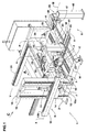
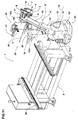
- It comprises a base frame 2 with which a bending head 3 is movably in engagement.
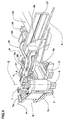
- the bending head 3 comprises at least one bending die 4 and one presser element 5 active on a pipe 6 to be bent against the action of said die 4 (Figs. 3 and 4). Said head 3 further comprises at least one locking jaw 7 to press and lock pipe 6 against die 4.
- the locking jaw 7 is rotatably movable relative to the presser element 5 together with die 4, at a bending axis Z.
- both the locking jaw 7 and presser element 5 are mounted on respective slides 7a, 5a enabling movement between first positions in which the jaw 7 and presser element 5 are spaced apart from die 4 and second positions in which the same are disposed close to die 4 to tighten the pipe 6 to be bent.
- the bending head 3 is provided with two dies 4 disposed spaced apart from each other along the bending axis Z and each provided with a presser element 5 and a locking jaw 7.
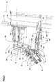
- the machine 1 further comprises a support and positioning device 9 for the head 3 which is linked to the base frame 2 (Figs. 1, 9, 11 and 13).
- the support and positioning device 9 is made up of a first support arm 10 movably in engagement with the base frame 2 by appropriate first 11 and second 12 actuating means.
- the first support arm 10 is moved by the first 11 and second 12 actuating means along a first translation direction X and a second translation direction Y perpendicular to the first one X, respectively.
- first support arm 10 is mounted on first sliding guides 13 oriented along the first translation direction X which is horizontal to the resting surface of the base frame 2, and formed on a first slide 14.
- the first slide 14 is in turn in engagement with second vertical sliding guides 15 oriented along the second translation direction Y and integral with a support body 16 mounted on the base frame 2.
- the first arm is therefore movable in a vertical plane defined by two translation directions X, Y along which the first 11 and second 12 actuating means are operatively active.
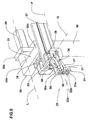
- the second arm 17 is driven by third actuating means 18 and can take a plurality of angular positions relative to the first support arm 10.
- the second arm 17 has a first end 17a connected to the first support arm 10 and a second end 17b rotatably linked to the bending head 3 at a second articulation axis K; the bending head 3 is therefore mounted in cantilevered fashion with respect to the support body 16.
- fourth actuating means 19 operatively active between the second arm 17 and bending head 3 enables relative positioning between the two elements.
- the first and second articulation axes J, K are parallel to each other and in addition they are perpendicular to both the first X and second Y translation directions.
- the bending axis Z is then perpendicular to both the articulation axes J, K and therefore said axis Z lies in a vertical plane parallel to the two translation directions X, Y, irrespective of the movements carried out by the support arms 10, 17 and the head 3 itself.
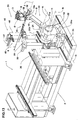
- the first support arm 10 is movable relative to the base frame 2 around a rotation axis I and in a translation direction U coincident with the longitudinal extension of the first support arm 10 and perpendicular to the rotation axis I itself.
- the first arm 10 is mounted on sliding guides, similar to those of the first embodiment and not shown, formed in a rotating plate 20.
- the rotating plate 20 is in turn hinged on the support body 16 mounted on the base frame 2.
- the first actuating means 11 is operatively active along a translation direction U to move the first support arm 10 on the sliding guides provided in plate 20, whereas the second actuating means 12 is operatively active around the rotation axis I, to rotate the rotating plate 20 together with the first arm 10.
- the rotation axis I is horizontal relative to the resting surface of the base frame 2, and consequently the first support arm 10 is movable in a vertical plane perpendicular to the rotation axis I itself.
- the second support arm 17 is rotatably connected to the first end 10a of the first arm 10 at the first articulation axis J that in the second embodiment shown is parallel to the rotation axis I.
- first and second articulation axes J, K are parallel to each other and in addition they are parallel to the rotation axis I.
- the bending axis Z is perpendicular to the rotation axis I and therefore said axis Z lies in a vertical plane perpendicular to the three axes I, J, K, irrespective of the movements carried out by the support arms 10, 17 and head 3.
- the first support arm 10 is mounted on an auxiliary arm 21 at a first end 21a of the auxiliary arm 21 itself; in turn, the auxiliary arm 21 is hinged at its second end 21b, opposite to the first one 21a, on a fixed base 22 placed close to the base frame 2.
- the auxiliary arm 21 together with the first and second support arms 10, 17, defines a multi-axis robot arm 23.
- the first arm 10 is movable relative to the auxiliary arm 21 around a first rotation axis A parallel to the first articulation axis J and the auxiliary arm 21 is hinged on the fixed base 22 at a second rotation axis B, parallel to the first articulation axis J as well.
- the first actuating means 11 is operatively active around the first rotation axis A, to rotate the first support arm 10 relative to the auxiliary arm 21, whereas the second actuating means 12 is operatively active around the second rotation axis B, to rotate the auxiliary arm 21 relative to the fixed base 22.
- the robot arm 23 is thus able to move axis Z of the bending head 3 in a vertical plane perpendicular to the two rotation axes A, B which are horizontal and parallel to each other and to the two articulation axes J, K, irrespective of the movements carried out by the support arms 10, 17, auxiliary arm 21 and head 3.
- the base 22 of the robot arm 23 as described in the third embodiment is slidably mounted on sliding guides 24 that, through an appropriate motor 24a, enable movement thereof along a translation direction C parallel to the ground and perpendicular to the two rotation axes A, B and the two articulation axes J, K.
- axis Z of the bending head 3 stays parallel to a vertical plane perpendicular to the four axes A, B, J, K, irrespective of the movements carried out by the support arms 10, 17, auxiliary arm 21, base 22 and head 3.
- the bending machine 1 further comprises (Figs. 5 and 6) a first gripping unit 25 for the pipe 6 to be bent which has a dual function, i.e. of picking up the pipe 6 from an appropriate feeding device 26 (Figs. 1, 9, 11 and 13) to bring it to an operating space that can be reached by the bending head 3, and of supporting the pipe during the bending operation.
- a first gripping unit 25 for the pipe 6 to be bent which has a dual function, i.e. of picking up the pipe 6 from an appropriate feeding device 26 (Figs. 1, 9, 11 and 13) to bring it to an operating space that can be reached by the bending head 3, and of supporting the pipe during the bending operation.
- the first gripping unit 25 is formed of two clamps 27, 28 disposed in such a manner as to hold the pipe 6 to be bent at two regions spaced apart from each other and with the longitudinal pipe axis disposed perpendicular to the bending axis Z, therefore in the right position for being engaged between the bending die 4 and locking jaw 7.
- first clamp 27 is aligned with the second clamp 28 along a first alignment direction P that, when clamps 27, 28 tighten pipe 6, is coincident with the longitudinal axis of the pipe itself.
- This first alignment direction P is perpendicular to the bending axis Z or, more specifically, to the plane in which the support and positioning device 9 shifts the bending axis Z.
- the second clamp 28 is movable along said first direction P, close to or away from the first clamp 27, through fifth actuating means 29 shown in Figs. 1 and 2, to enable gripping of pipe 6 at two positions disposed a varying axial distance from each other.
- Each clamp 27, 28 comprises two arms 30, 31 (Figs. 5 and 6), movable between a first position in which they are spaced apart from each other and a second position in which they are close to each other to tighten the interposed pipe 6.
- Each arm 30, 31 at an end 30a, 31a thereof has at least one gripping cavity 32 (Fig. 6) the shape of which matches that of the pipe 6 to be tighten.
- the mating cavities 32 form a passage for pipe 6.
- the first gripping unit 25 is therefore able to support a pipe 6 made up of two rigid portions connected by a median flexible stretch at appropriate connecting fittings.
- each clamp 27, 28 tightens one of the rigid portions close to its connection with the flexible stretch and the mutual distance of said clamps can be adjusted based on the length of the flexible stretch itself.
- arms 30, 31 in the first clamp 27 are provided with gripping ends 30a, 31a, each of which is provided with two cavities of different radius 32a, 32b so that pipe 6 can be clamped both on its nominal diameter and on the diameter of the connecting fitting.
- the first clamp 27 is also movable along a second alignment direction Q perpendicular to the first alignment direction P.
- the first clamp 27 is mounted on a first platform 33 movable on first rails 34 integral with a third support arm 35 and oriented along the second alignment direction Q.
- the second clamp 28 is mounted on a second platform 36 slidable on at least one second rail 37 integral with the third arm 35 and oriented along the first alignment direction P.
- the two clamps 27, 28 can be also used as a single clamp, since the second clamp 28, as clearly shown in Fig. 6, can be also positioned between the open ends 30a, 31a of the arms of the first clamp 27.
- the third support arm 35 has a first end 35a to which the first gripping unit 25 is fastened, and a second end 35b rotatably linked to the end 38a of a first support column 38 (Fig. 5).
- the third support arm 35 is able to rotate, through appropriate sixth actuating means 39, around a third articulation axis L located at the second end 35b, for orientation of the gripping unit 25.
- the first column 38 is in engagement with third horizontal rails 40 of a third platform 41 enabling translation of column 38 through seventh actuating means 42 along a first movement direction V.
- the first movement direction V is parallel to the first translation direction X; in the second embodiment (Figs. 9 and 10) the first movement direction V is perpendicular to the rotation axis I; finally, in the third embodiment (Figs. 11 and 12) and fourth embodiment (Figs. 13 and 14) said first movement direction V is perpendicular to the two rotation axes A, B.
- the third platform 41 is in turn in engagement with fourth horizontal rails 43 integral with the base frame 2 and extending at right angles to the third horizontal rails 40. Therefore the first column 38, through the fourth rails 43 and eighth actuating means 44 (Figs. 1 and 5) dedicated thereto, can also move along a second movement direction W perpendicular to the first movement direction V.
- the third articulation axis L is parallel to the first alignment direction P and the second movement direction W so that pipe 6 picked up from the feeding device 26 moves always parallel to itself.
- the draw-bending machine 1 finally comprises a rotation unit 45 (Figs. 1, 9, 11 and 13) to rotate pipe 6 through 180° and enable the bending head 3 to bend both ends of the pipe 6 itself with ease.
- the rotation unit 45 consists of a second gripping unit 46 mounted on a fourth support arm 47 in turn rotatably mounted on a second fixed support column 48 put close to the base frame 2.
- the second gripping unit 46 as well comprises a third clamp 49 in alignment with a fourth clamp 50 along a third alignment direction R that, when clamps 49, 50 tighten pipe 6, is coincident with the longitudinal axis of the pipe 6 itself.
- the second gripping unit 46 and fourth support arm 47 rotate about a fourth articulation axis M perpendicular to the third alignment direction R.
- the second gripping unit 46 is movable through an angle of 180°, between two opposite positions in which the third alignment direction R and consequently the longitudinal axis of pipe 6, is parallel to the first alignment direction P.
- the first gripping unit 25 After arrangement of pipes 6 to be bent in the feeding device 26, the first gripping unit 25 is moved close to the feeding device 26 and said unit, by means of clamps 27, 28, picks a pipe 6 up disposing the longitudinal axis of the pipe 6 itself along the first alignment direction P.
- the first gripping unit 25 brings pipe 6 still parallel to itself into the operating space that can be reached by the bending head 3.
- the support and positioning device 9 moves the bending head 3 until engagement of pipe 6 between one of the two bending dies 4, the respective presser element 5 and the locking jaw 7, the two last-mentioned elements being spaced apart from die 4.
- the head 3 and related bending axis Z are inclined in a first reference direction Z' selected on the basis of the plane in which the curve must lie.
- the bending plane i.e. the plane in which the elbow shape to be formed on pipe 6 lies, is the plane perpendicular to the bending axis Z.
- the locking jaw 7 and presser element 5 move close to die 4 to tighten pipe 6, and subsequently the die 4 and locking jaw 7 rotate with respect to the presser element 5 around the bending axis Z to form the curve or bend.
- the working cycle involves moving of the bending head 3 away from pipe 6, axial sliding of the pipe 6 itself to change the bending region, and subsequent moving of the bending head 3 close to the pipe according to a second reference direction Z" different from the first one Z'.
- the reference directions Z', Z" according to which axis Z is inclined stay in a plane perpendicular to the first alignment direction P.
- the handling and locking means 51 is able to rotate pipe 6 through 180°.
- the first gripping unit 25 brings pipe 6 close to the second gripping unit 46 of the rotation unit 45.
- the second gripping unit 46 grasps pipe 6 and, through rotation through 180° around the fourth articulation axis M, turns it over and returns it to the gripping unit 25 to bring the unworked end towards the bending head 3.
- the invention achieves important advantages.
- draw-bending machine in accordance with the present invention enables pipes made up of two rigid portions connected together by a flexible stretch to be bent in different planes.
- the particular structure of the first gripping unit allows the two rigid portions of the pipe to be grasped irrespective of the length of the flexible stretch whereas the bending head is able to rotate around the fixed pipe to form curves in any wished and intended plane.
- the machine in accordance with the invention therefore enables passage from the assembled components not yet bent to the finished product without being obliged to store bent pipes before assembling. In this way there is no risk of each bent rigid pipe being damaged during storage and subsequent picking up for assembling.
- draw-bending machine of the invention enables the same bending head moved by the support and positioning device to be also used to discharge the finished pipe into an unloading area selected each time, or even into a further working station.
Priority Applications (5)
| Application Number | Priority Date | Filing Date | Title |
|---|---|---|---|
| ES01830619T ES2194827T3 (es) | 2001-10-02 | 2001-10-02 | Maquina para curvar con traccion. |
| EP01830619A EP1291094B1 (de) | 2001-10-02 | 2001-10-02 | Vorrichtung und Verfahren zum Ziehbiegen |
| DE60100147T DE60100147T2 (de) | 2001-10-02 | 2001-10-02 | Vorrichtung und Verfahren zum Ziehbiegen |
| US10/246,614 US6694794B2 (en) | 2001-10-02 | 2002-09-17 | Draw-bending machine |
| CA002411795A CA2411795A1 (en) | 2001-10-02 | 2002-11-13 | Draw-bending machine |
Applications Claiming Priority (2)
| Application Number | Priority Date | Filing Date | Title |
|---|---|---|---|
| EP01830619A EP1291094B1 (de) | 2001-10-02 | 2001-10-02 | Vorrichtung und Verfahren zum Ziehbiegen |
| CA002411795A CA2411795A1 (en) | 2001-10-02 | 2002-11-13 | Draw-bending machine |
Publications (2)
| Publication Number | Publication Date |
|---|---|
| EP1291094A1 true EP1291094A1 (de) | 2003-03-12 |
| EP1291094B1 EP1291094B1 (de) | 2003-03-26 |
Family
ID=32963070
Family Applications (1)
| Application Number | Title | Priority Date | Filing Date |
|---|---|---|---|
| EP01830619A Expired - Lifetime EP1291094B1 (de) | 2001-10-02 | 2001-10-02 | Vorrichtung und Verfahren zum Ziehbiegen |
Country Status (5)
| Country | Link |
|---|---|
| US (1) | US6694794B2 (de) |
| EP (1) | EP1291094B1 (de) |
| CA (1) | CA2411795A1 (de) |
| DE (1) | DE60100147T2 (de) |
| ES (1) | ES2194827T3 (de) |
Cited By (7)
| Publication number | Priority date | Publication date | Assignee | Title |
|---|---|---|---|---|
| EP1350578A1 (de) * | 2002-04-03 | 2003-10-08 | Trumpf Rohrtechnik GmbH + Co. KG | Biegemaschine zum Biegen von stangen- und/oder von stabartigen Werkstücken, insbesondere von Rohren |
| FR2859653A1 (fr) * | 2003-09-12 | 2005-03-18 | Silfax Sa | Machine orbitale pour le cintrage des tubes |
| DE102013200850A1 (de) * | 2013-01-21 | 2014-07-24 | Wafios Aktiengesellschaft | Vorrichtung zum Biegen strangförmiger Werkstücke |
| CN104259342A (zh) * | 2014-09-11 | 2015-01-07 | 建科机械(天津)股份有限公司 | 钢筋弯曲机上的锁紧机构 |
| EP3046234A1 (de) * | 2015-01-14 | 2016-07-20 | A.S.EN. Ansaldo Sviluppo Energia S.r.l. | Verfahren und vorrichtung zum umformen von mindestens einer generatorstange |
| CN109549699A (zh) * | 2018-12-04 | 2019-04-02 | 中南大学湘雅医院 | 弧线型钛合金医用内固定板自动塑形机构 |
| IT201900006821A1 (it) * | 2019-05-14 | 2020-11-14 | Star Tech S R L | Macchina per la curvatura di elementi allungati quali barre, tubi e simili e metodo di funzionamento di tale macchina |
Families Citing this family (21)
| Publication number | Priority date | Publication date | Assignee | Title |
|---|---|---|---|---|
| ES2247457T3 (es) * | 2002-06-28 | 2006-03-01 | Oscam S.P.A. | Instalacion para el tratamiento de barras metalicas con medios mejorados para transferir dichas barras y procedimiento previsto para ello. |
| DE502004003557D1 (de) * | 2003-08-05 | 2007-05-31 | Rosenberger Ag | Verfahren zum biegen von werkstücken |
| CN100391641C (zh) * | 2006-03-20 | 2008-06-04 | 上海圣诺机床有限公司 | 可拆装组合式后定位结构 |
| US7254972B1 (en) * | 2006-06-28 | 2007-08-14 | Chia Sheng Machinery Co., Ltd. | Moving mold mechanism of a pipe bending machine |
| DE502007005038D1 (de) | 2007-02-07 | 2010-10-28 | Wafios Ag | Biegemaschine |
| ATE429987T1 (de) | 2007-03-14 | 2009-05-15 | Wafios Ag | Greifvorrichtung zum ergreifen und haltern länglicher werkstücke, insbesondere bei biegemaschinen |
| AT505657B1 (de) * | 2007-08-16 | 2009-03-15 | Hammerschmid Maschb Gmbh | Vorrichtung und verfahren zum biegen von halbzeugen |
| DE202007015831U1 (de) * | 2007-11-13 | 2009-03-26 | Wilhelm Karmann Gmbh | Arbeitsstation zur Bearbeitung eines Werkstücks, insbesondere eines Gestängeelementes eines Verdeckgestänges eines Cabriolet-Fahrzeugs |
| EP2177287B1 (de) | 2008-10-17 | 2011-11-30 | WAFIOS Aktiengesellschaft | Stützbackenanordnung zum gleitenden seitlichen Abstützen von stab- und rohrförmigen Werkstücken an Biegemaschinen |
| JP5330064B2 (ja) * | 2009-04-08 | 2013-10-30 | 株式会社オプトン | 曲げ加工装置 |
| JP5405878B2 (ja) * | 2009-04-08 | 2014-02-05 | 株式会社オプトン | 曲げ加工装置 |
| JP5405879B2 (ja) * | 2009-04-08 | 2014-02-05 | 株式会社オプトン | 曲げ加工装置 |
| IT1401361B1 (it) | 2010-06-10 | 2013-07-18 | Blm Spa | Macchina curvatubi con sistema di caricamento automatico e metodo per il caricamento automatico di tubi sulla testa di curvatura di una macchina curvatubi. |
| JP6101454B2 (ja) * | 2012-09-04 | 2017-03-22 | 株式会社アマダホールディングス | ワーク加工装置及び該ワーク加工装置における金型の移動方法 |
| USD755861S1 (en) * | 2014-08-15 | 2016-05-10 | Trumpf Gmbh + Co. Kg | Bending machine |
| JP1539124S (de) * | 2014-08-15 | 2015-11-30 | ||
| AT516371B1 (de) * | 2014-12-02 | 2016-05-15 | Stonawski Rudolf | Einrichtung zum Biegen eines Profil-Werkstücks |
| CN104858272B (zh) * | 2015-05-11 | 2016-08-10 | 武汉思瑞法机器人制造有限公司 | 管道折弯机 |
| IT201600119591A1 (it) * | 2016-11-25 | 2018-05-25 | Crippa Spa | Macchina per curvare materiale filiforme quale un tubo con un sistema di caricamento contemporaneo del tubo da curvare e scarico del tubo curvato |
| CN107127231A (zh) * | 2017-06-05 | 2017-09-05 | 肇庆市端州区麒诺机械科技有限公司 | 管道折弯机 |
| IT202100011660A1 (it) * | 2021-05-06 | 2022-11-06 | Schnell Spa | Metodo e apparecchiatura per la piegatura di barre |
Citations (6)
| Publication number | Priority date | Publication date | Assignee | Title |
|---|---|---|---|---|
| US3299681A (en) * | 1960-03-22 | 1967-01-24 | Baldwin Lima Hamilton Corp | Program controlled tube bender |
| DE3620151A1 (de) * | 1985-06-19 | 1987-02-26 | Asea Ab | Verfahren und robotereinrichtung zum biegen von stangenfoermigen materialien oder werkstuecken |
| GB2187666A (en) * | 1986-03-15 | 1987-09-16 | Pressbend Ltd | Pipe bending apparatus |
| US4945747A (en) * | 1989-05-11 | 1990-08-07 | Chuo Electric Manufacturing Co., Ltd. | Apparatus for bending elongated materials in any direction |
| EP0538207A2 (de) * | 1991-10-16 | 1993-04-21 | FABBRICA MACCHINE CURVATUBI CRIPPA AGOSTINO S.p.A. | Multi-funktionnelle Rohrbiegemaschine |
| EP1065015A1 (de) * | 1999-06-21 | 2001-01-03 | TI Group Automotive Systems | Vorrichtung zum Biegen langer Metallelemente wie Rohre |
Family Cites Families (12)
| Publication number | Priority date | Publication date | Assignee | Title |
|---|---|---|---|---|
| JPH02299724A (ja) * | 1989-05-11 | 1990-12-12 | Chuo Electric Mfg Co Ltd | 曲げ加工装置 |
| IT1236462B (it) * | 1989-12-29 | 1993-03-09 | Fabro Giorgio Del | Gruppo piegatore a satellite |
| JPH0565440U (ja) * | 1992-02-03 | 1993-08-31 | 安川商事株式会社 | ワイヤベンディング装置 |
| US5825759A (en) * | 1994-10-26 | 1998-10-20 | Telefonaktiebolaget Lm Ericsson | Distributing network services and resources in a mobile communications network |
| IT1290141B1 (it) * | 1997-03-21 | 1998-10-19 | Blm Spa | Macchina per curvare materiale filiforme come tubi barre o profilati |
| US6098108A (en) * | 1997-07-02 | 2000-08-01 | Sitara Networks, Inc. | Distributed directory for enhanced network communication |
| US6338117B1 (en) * | 1998-08-28 | 2002-01-08 | International Business Machines Corporation | System and method for coordinated hierarchical caching and cache replacement |
| US20020073167A1 (en) * | 1999-12-08 | 2002-06-13 | Powell Kyle E. | Internet content delivery acceleration system employing a hybrid content selection scheme |
| US6505200B1 (en) * | 2000-07-06 | 2003-01-07 | International Business Machines Corporation | Application-independent data synchronization technique |
| WO2002069172A1 (en) * | 2001-02-22 | 2002-09-06 | Didera, Inc. | Systems and methods for managing distributed database resources |
| US6820116B1 (en) * | 2001-12-21 | 2004-11-16 | Nokia Corporation | Mobile browsing booster system |
| US20040009815A1 (en) * | 2002-06-26 | 2004-01-15 | Zotto Banjamin O. | Managing access to content |
-
2001
- 2001-10-02 DE DE60100147T patent/DE60100147T2/de not_active Expired - Fee Related
- 2001-10-02 EP EP01830619A patent/EP1291094B1/de not_active Expired - Lifetime
- 2001-10-02 ES ES01830619T patent/ES2194827T3/es not_active Expired - Lifetime
-
2002
- 2002-09-17 US US10/246,614 patent/US6694794B2/en not_active Expired - Fee Related
- 2002-11-13 CA CA002411795A patent/CA2411795A1/en not_active Abandoned
Patent Citations (6)
| Publication number | Priority date | Publication date | Assignee | Title |
|---|---|---|---|---|
| US3299681A (en) * | 1960-03-22 | 1967-01-24 | Baldwin Lima Hamilton Corp | Program controlled tube bender |
| DE3620151A1 (de) * | 1985-06-19 | 1987-02-26 | Asea Ab | Verfahren und robotereinrichtung zum biegen von stangenfoermigen materialien oder werkstuecken |
| GB2187666A (en) * | 1986-03-15 | 1987-09-16 | Pressbend Ltd | Pipe bending apparatus |
| US4945747A (en) * | 1989-05-11 | 1990-08-07 | Chuo Electric Manufacturing Co., Ltd. | Apparatus for bending elongated materials in any direction |
| EP0538207A2 (de) * | 1991-10-16 | 1993-04-21 | FABBRICA MACCHINE CURVATUBI CRIPPA AGOSTINO S.p.A. | Multi-funktionnelle Rohrbiegemaschine |
| EP1065015A1 (de) * | 1999-06-21 | 2001-01-03 | TI Group Automotive Systems | Vorrichtung zum Biegen langer Metallelemente wie Rohre |
Cited By (10)
| Publication number | Priority date | Publication date | Assignee | Title |
|---|---|---|---|---|
| EP1350578A1 (de) * | 2002-04-03 | 2003-10-08 | Trumpf Rohrtechnik GmbH + Co. KG | Biegemaschine zum Biegen von stangen- und/oder von stabartigen Werkstücken, insbesondere von Rohren |
| FR2859653A1 (fr) * | 2003-09-12 | 2005-03-18 | Silfax Sa | Machine orbitale pour le cintrage des tubes |
| US7093475B2 (en) | 2003-09-12 | 2006-08-22 | Silfax | Orbital machine for bending tubes |
| DE102013200850A1 (de) * | 2013-01-21 | 2014-07-24 | Wafios Aktiengesellschaft | Vorrichtung zum Biegen strangförmiger Werkstücke |
| DE102013200850B4 (de) * | 2013-01-21 | 2015-01-22 | Wafios Aktiengesellschaft | Vorrichtung zum Biegen strangförmiger Werkstücke |
| CN104259342A (zh) * | 2014-09-11 | 2015-01-07 | 建科机械(天津)股份有限公司 | 钢筋弯曲机上的锁紧机构 |
| EP3046234A1 (de) * | 2015-01-14 | 2016-07-20 | A.S.EN. Ansaldo Sviluppo Energia S.r.l. | Verfahren und vorrichtung zum umformen von mindestens einer generatorstange |
| CN109549699A (zh) * | 2018-12-04 | 2019-04-02 | 中南大学湘雅医院 | 弧线型钛合金医用内固定板自动塑形机构 |
| CN109549699B (zh) * | 2018-12-04 | 2021-05-25 | 中南大学湘雅医院 | 弧线型钛合金医用内固定板自动塑形机构 |
| IT201900006821A1 (it) * | 2019-05-14 | 2020-11-14 | Star Tech S R L | Macchina per la curvatura di elementi allungati quali barre, tubi e simili e metodo di funzionamento di tale macchina |
Also Published As
| Publication number | Publication date |
|---|---|
| ES2194827T3 (es) | 2003-12-01 |
| US6694794B2 (en) | 2004-02-24 |
| US20030061853A1 (en) | 2003-04-03 |
| EP1291094B1 (de) | 2003-03-26 |
| DE60100147T2 (de) | 2004-01-29 |
| DE60100147D1 (de) | 2003-05-22 |
| CA2411795A1 (en) | 2004-05-13 |
Similar Documents
| Publication | Publication Date | Title |
|---|---|---|
| EP1291094B1 (de) | Vorrichtung und Verfahren zum Ziehbiegen | |
| US7104100B2 (en) | Bending device for tube | |
| US3431759A (en) | Forming apparatus | |
| KR100818840B1 (ko) | 장척재의 절곡 가공 장치 | |
| JPS59183938A (ja) | 索状材料を曲げる機械 | |
| US8337137B2 (en) | Transfer module for transferring parts between work stations | |
| TWI606875B (zh) | 具有自動裝載系統之彎管機以及用於將管件自動裝載於彎管機的彎曲頭上之方法 | |
| CN113453819B (zh) | 用于自动转换工装系统的方法和装置 | |
| CN109500592A (zh) | 一种插弯头机 | |
| JP2648369B2 (ja) | バレル形コイルバネの成形方法及びその装置 | |
| EP4153369B1 (de) | Verfahren und vorrichtung zur verarbeitung von stangen | |
| US7076984B2 (en) | Bending machine and tube support and drive device thereof | |
| WO2023112070A1 (en) | Apparatus and method for bending bars | |
| EP1468756A1 (de) | Verfahren und Vorrichtung zum Biegen von rohrförmigen Werkstücken mit veränderlichem Biegeradius | |
| CN210616510U (zh) | 弯管进出料自动夹取移动装置 | |
| CN112718978B (zh) | 一种管件旋转夹持器及机器人弯管工作站 | |
| CN215378705U (zh) | 一种圆线定子引出线整形设备 | |
| CN112453134B (zh) | 一种管件旋转夹持器及包含其的机器人弯管工作站 | |
| JPH0513011B2 (de) | ||
| JPH0513012B2 (de) | ||
| CN107020616A (zh) | 小型机械气动手爪及使用方法 | |
| CN113241906A (zh) | 一种圆线定子引出线整形设备 | |
| US4683649A (en) | Device for assembling return bend to coil | |
| US4747208A (en) | Device for assembling return bend to coil | |
| US8220304B2 (en) | Machine for cambering, forming, folding or bending bars, wires or extruded shapes |
Legal Events
| Date | Code | Title | Description |
|---|---|---|---|
| GRAH | Despatch of communication of intention to grant a patent |
Free format text: ORIGINAL CODE: EPIDOS IGRA |
|
| GRAH | Despatch of communication of intention to grant a patent |
Free format text: ORIGINAL CODE: EPIDOS IGRA |
|
| PUAI | Public reference made under article 153(3) epc to a published international application that has entered the european phase |
Free format text: ORIGINAL CODE: 0009012 |
|
| GRAA | (expected) grant |
Free format text: ORIGINAL CODE: 0009210 |
|
| 17P | Request for examination filed |
Effective date: 20020425 |
|
| AK | Designated contracting states |
Kind code of ref document: A1 Designated state(s): AT BE CH CY DE DK ES FI FR GB GR IE IT LI LU MC NL PT SE TR |
|
| AX | Request for extension of the european patent |
Extension state: AL LT LV MK RO SI |
|
| AK | Designated contracting states |
Designated state(s): DE ES FR GB IT |
|
| REG | Reference to a national code |
Ref country code: GB Ref legal event code: FG4D |
|
| REG | Reference to a national code |
Ref country code: IE Ref legal event code: FG4D |
|
| REF | Corresponds to: |
Ref document number: 60100147 Country of ref document: DE Date of ref document: 20030522 Kind code of ref document: P |
|
| LTIE | Lt: invalidation of european patent or patent extension |
Effective date: 20030326 |
|
| AKX | Designation fees paid |
Designated state(s): DE ES FR GB IT |
|
| ET | Fr: translation filed | ||
| PLBE | No opposition filed within time limit |
Free format text: ORIGINAL CODE: 0009261 |
|
| STAA | Information on the status of an ep patent application or granted ep patent |
Free format text: STATUS: NO OPPOSITION FILED WITHIN TIME LIMIT |
|
| 26N | No opposition filed |
Effective date: 20031230 |
|
| REG | Reference to a national code |
Ref country code: IE Ref legal event code: MM4A |
|
| PGFP | Annual fee paid to national office [announced via postgrant information from national office to epo] |
Ref country code: GB Payment date: 20050928 Year of fee payment: 5 |
|
| PGFP | Annual fee paid to national office [announced via postgrant information from national office to epo] |
Ref country code: DE Payment date: 20050929 Year of fee payment: 5 |
|
| PGFP | Annual fee paid to national office [announced via postgrant information from national office to epo] |
Ref country code: FR Payment date: 20051010 Year of fee payment: 5 |
|
| PGFP | Annual fee paid to national office [announced via postgrant information from national office to epo] |
Ref country code: ES Payment date: 20051129 Year of fee payment: 5 |
|
| PGFP | Annual fee paid to national office [announced via postgrant information from national office to epo] |
Ref country code: IT Payment date: 20061031 Year of fee payment: 6 |
|
| PG25 | Lapsed in a contracting state [announced via postgrant information from national office to epo] |
Ref country code: DE Free format text: LAPSE BECAUSE OF NON-PAYMENT OF DUE FEES Effective date: 20070501 |
|
| GBPC | Gb: european patent ceased through non-payment of renewal fee |
Effective date: 20061002 |
|
| REG | Reference to a national code |
Ref country code: FR Ref legal event code: ST Effective date: 20070629 |
|
| PG25 | Lapsed in a contracting state [announced via postgrant information from national office to epo] |
Ref country code: GB Free format text: LAPSE BECAUSE OF NON-PAYMENT OF DUE FEES Effective date: 20061002 |
|
| REG | Reference to a national code |
Ref country code: ES Ref legal event code: FD2A Effective date: 20061003 |
|
| PG25 | Lapsed in a contracting state [announced via postgrant information from national office to epo] |
Ref country code: ES Free format text: LAPSE BECAUSE OF NON-PAYMENT OF DUE FEES Effective date: 20061003 Ref country code: FR Free format text: LAPSE BECAUSE OF NON-PAYMENT OF DUE FEES Effective date: 20061031 |
|
| PG25 | Lapsed in a contracting state [announced via postgrant information from national office to epo] |
Ref country code: IT Free format text: LAPSE BECAUSE OF NON-PAYMENT OF DUE FEES Effective date: 20071002 |