EP1290660B1 - System und anordnung zur bestimmung des gefahrengrads in einer gefährlichen situation - Google Patents
System und anordnung zur bestimmung des gefahrengrads in einer gefährlichen situation Download PDFInfo
- Publication number
- EP1290660B1 EP1290660B1 EP01918071A EP01918071A EP1290660B1 EP 1290660 B1 EP1290660 B1 EP 1290660B1 EP 01918071 A EP01918071 A EP 01918071A EP 01918071 A EP01918071 A EP 01918071A EP 1290660 B1 EP1290660 B1 EP 1290660B1
- Authority
- EP
- European Patent Office
- Prior art keywords
- hazard
- sensor
- situation
- hazard level
- sensors
- Prior art date
- Legal status (The legal status is an assumption and is not a legal conclusion. Google has not performed a legal analysis and makes no representation as to the accuracy of the status listed.)
- Expired - Lifetime
Links
- 231100001261 hazardous Toxicity 0.000 title description 17
- 238000011156 evaluation Methods 0.000 claims abstract description 10
- 230000036962 time dependent Effects 0.000 claims abstract description 3
- 238000011161 development Methods 0.000 claims description 36
- 230000009471 action Effects 0.000 claims description 27
- 239000007789 gas Substances 0.000 claims description 16
- 230000008859 change Effects 0.000 claims description 13
- 230000006870 function Effects 0.000 claims description 10
- 230000001419 dependent effect Effects 0.000 claims description 6
- 230000005855 radiation Effects 0.000 claims description 3
- 230000018109 developmental process Effects 0.000 description 29
- 238000005259 measurement Methods 0.000 description 18
- 230000008901 benefit Effects 0.000 description 17
- CURLTUGMZLYLDI-UHFFFAOYSA-N Carbon dioxide Chemical compound O=C=O CURLTUGMZLYLDI-UHFFFAOYSA-N 0.000 description 12
- 229910002092 carbon dioxide Inorganic materials 0.000 description 7
- 230000033001 locomotion Effects 0.000 description 7
- 239000001569 carbon dioxide Substances 0.000 description 5
- 238000012544 monitoring process Methods 0.000 description 5
- 238000000034 method Methods 0.000 description 4
- 230000003213 activating effect Effects 0.000 description 3
- 238000012986 modification Methods 0.000 description 3
- 230000004048 modification Effects 0.000 description 3
- 230000008569 process Effects 0.000 description 3
- 238000009423 ventilation Methods 0.000 description 3
- 230000008878 coupling Effects 0.000 description 2
- 238000010168 coupling process Methods 0.000 description 2
- 238000005859 coupling reaction Methods 0.000 description 2
- 230000000694 effects Effects 0.000 description 2
- 239000000779 smoke Substances 0.000 description 2
- 230000004913 activation Effects 0.000 description 1
- 238000010276 construction Methods 0.000 description 1
- 238000013461 design Methods 0.000 description 1
- 238000001514 detection method Methods 0.000 description 1
- 230000001627 detrimental effect Effects 0.000 description 1
- 238000010586 diagram Methods 0.000 description 1
- 238000006073 displacement reaction Methods 0.000 description 1
- 239000002360 explosive Substances 0.000 description 1
- 231100001267 hazard identification Toxicity 0.000 description 1
- 230000006872 improvement Effects 0.000 description 1
- 230000002401 inhibitory effect Effects 0.000 description 1
- 238000007689 inspection Methods 0.000 description 1
- 238000005065 mining Methods 0.000 description 1
- 230000001473 noxious effect Effects 0.000 description 1
- 239000010893 paper waste Substances 0.000 description 1
- 230000000246 remedial effect Effects 0.000 description 1
- 230000004044 response Effects 0.000 description 1
- 238000012360 testing method Methods 0.000 description 1
- 239000002341 toxic gas Substances 0.000 description 1
Images

Classifications
-
- G—PHYSICS
- G08—SIGNALLING
- G08B—SIGNALLING OR CALLING SYSTEMS; ORDER TELEGRAPHS; ALARM SYSTEMS
- G08B17/00—Fire alarms; Alarms responsive to explosion
Definitions
- the present invention relates generally to a system for initially establishing the occurrence of a hazardous situation within a space and, when necessary, calculating a level or degree of urgency of said situation.
- the invention also relates to the process of making requisite calculations within said second hazard level.
- occupancy hazard situation an event whose hazard level-related values have been found to have passed the upper limit of the first hazard level, through the medium of measurements, calculations and/or observations, and where the established event and its development shall be placed under special observation through the agency of sensors disposed in said space with a preventative purpose in mind. In this case, development of the hazard situation shall lie beneath the upper limit set for the second hazard level.
- a hazard situation that calls for measures to be set into motion shall be understood that an occurring hazard situation has been monitored over a period of time and that it has been established that said situation has developed towards a higher degree of urgency or higher values of hazard levels that require a decision as to whether measures shall be activated, by selecting and activating one or more of a plurality of available measures, whereas development towards a lower hazard level shall obviate the need of activating or setting into motion any of the available measures.
- the measures concerned may comprise ocular superintendence of the event, shutting down evacuation fans, closing fire doors, or the undertaking of correspondingly simple measures.
- hazard situations that call for greater action shall be understood as a measure-calling hazard situation that has been monitored or supervised and one or more measures taken, but where the hazard situation has worsened and therewith requires one or more actions to be instigated immediately.
- the values related to development of the hazard situation shall lie above the upper limit of the third hazard level.
- such actions are of a more comprehensive nature than the simpler measures taken at lower hazard levels and may involve summoning fire defence services, police services and other personnel for a co-ordinated effort to restrict and fight the event.
- the location of the hazard situation shall be understood, for instance, one or more established and calculated geographical points in a one-dimensional, two-dimensional or three-dimensional co-ordinate system where the calculation is based on a plurality of time-related signals outputted from a plurality of sensors where a monitored hazard situation is concentrated and where a hazardous situation is imminent
- the invention relates to a system and to an arrangement for evaluating the development of a hazardous situation within a well-defined space or area with the aid of the introduction of terms such as hazard levels, and in the event of an occurring hazard situation to provide provisions for establishing the geographic position of the hazard situation with the aid of information relating to the development and obtained from a plurality of sensors for detecting mutually the same or mutually different criteria and further to the features stated in the preamble of claim 1.
- a plurality of sensors shall be provided within said space or area adapted for one or more criteria and be capable of evaluating current, or prevailing, values related to hazard levels.
- tunnels such as tunnels intended for railtrack vehicles, automotive vehicles, and the like
- TV cameras or sensors normally one-category sensors
- This system is based on the ability of the actual operators to establish that a hazard exists, such as a fire hazard, and themselves determine the level of the hazard and its location and to determine the need for activating one or more of a plurality of available measures or actions.
- the most drastic action that can be considered applicable in such a situation is to close the tunnel to traffic, to call the police and fire brigade for relevant action when a single sensor is activated. Such action will cause a train or cars and other vehicles present in the tunnel to be enclosed therein.
- the last mentioned application should also take into account the air currents that normally exist and the strong, more prevailing air flows or air streams that are generated by movement of a train through the tunnel system.
- This patent Publication discloses a system for evaluating the development of a hazard situation (fire, see abstract) within a space or an area (sensors are placed in an area) with the aid of hazard level concepts (probabilities of fire see for example tables 2 and 8 and col. 4, lines 17-20, finally see fig.
- output layer is a hazard level, ie fire probability) and, upon the occurrence of a hazard situation, creating conditions whereby the hazard level of the hazard situation can be obtained on the basis of information relating to the development of said hazard situation deriving from a plurality of sensors that function in respect of mutually the same or mutually different criteria (see table 2, smell, smoke), [characterised in that] wherein information relating to the time-wise variation of output signals related to the hazard situation and obtained from a first sensor and also relating to the time-wise variation of similar output signals obtained from a second sensor can be stored (see for example fig.
- step 413 which stores the input data); in that a comparison between the momentary values of the output signals (see for example table 2, "value at given time") and/or measured time related changes ("difference of smoke/smell” see for example table 2) generate a hazard level value (fire probability) for the occurring hazard situation through the medium of a calculating circuit (weighted "intermediate layer", see for example programme 700 in fig. 5); and in that solely the hazard level values that exceed a first hazard level of an indicated hazard situation are chosen to follow the development of the hazard situation (col. 11, lines 43-51 and fig. 5, steps 417, 418) by means of the output signals from said sensors (signals obtained in step 412 of fig. 5).
- Another technical problem is one of being able to realise the significance of and the advantages associated with allowing the time duration between said significant changes and respective distances between the sensors used to constitute criteria for calculating the hazard level of the hazardous situation.
- Still another technical problem is one of realising the significance of and the advantages associated with inhibiting each time-wise and determinable variation beneath the upper limit of a first hazard level while registering and monitoring each time-wise significant change beneath a second hazard level and above said first hazard level, so as to enable the development of the event or hazardous situation to be evaluated.
- Another technical problem is resides in realising the significance of and the advantages associated with allowing the chosen thresholds of said hazard levels to be inverted to one or more values for the first time derivative of an established variation.
- Another technical problem also resides in realising the significance of and the advantages associated with adapting the threshold values of said hazard levels to the criteria that respective sensors are intended to detect and/or sensor-associated environments.
- Yet another technical problem is one of realising the significance of and the advantages associated with allowing further criteria to constitute a measured value of the air flow in a space, with respect to velocity and/or the direction of said air flow and/or the value given by a temperature detecting sensor.
- Another technical problem resides in realising the significance of and the advantages associated with allowing said sensors to be adapted to evaluate the concentration of airborne gases, such as CO, CO 2 and/or other (nox) gases.
- Still another technical problem is one of realising the significance of and the advantages associated with connecting to said control unit a sensor that functions to determine the direction and velocity of an air flow in said space.
- Another technical problem is one of realising the significance of and the advantages associated with connecting to said computer equipment, when applicable, a sensor that functions to evaluate IR radiation.
- Still another technical problem is one of realising the significance of and the advantages afforded with connecting to said computer equipment, when applicable, a heat sensor or temperature detector.
- Another technical problem is one of realising the significance of and the advantages associated with taking into account and using priority-dependent and weighted measurement values in the computing circuit.
- the present invention is based on a system and on an arrangement for enabling the development of a hazardous situation in a space or in an area to be evaluated with the aid of hazard level concepts as stated in the preamble of claim 1
- the present invention adds to the prior art the features mentioned in the characterizing part of claim 1.
- Those advantages primarily significant to the present invention reside in the provision of conditions for initially establishing and noting a hazard situation and by calculated control of the development of said situation, by utilising the sensor-associated output signal time-wise variation of the current hazard situation to evaluate the time-wise development of the hazard level values and therewith enable a development of a hazard to be followed and an alarm to be given or necessary measures or actions to be taken at an early stage.
- the invention can be developed still further and made more complex for more accurate evaluation of different threshold values and calculation of occurring hazard levels, in order to enable one or more different measures or actions available from a plurality of measures or actions to be taken, by using sensors that operate to detect several criteria or by including more sensors.
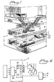
- Figure 1 is intended to illustrate an underground railway environment, subway environment, in which the present invention can be applied.
- the figure shows in perspective a subway section 1 which is monitored by an inventive arrangement.
- the invention will be described initially on the basis of solely three sensors 2, 3 and 4 placed at a chosen distance apart in the subway section 1.
- Each of the sensors 2, 3 and 4 may be adapted to detect the presence of one or more gases.
- the sensor 2 is adapted to detect and register ongoing or current carbon dioxide values, CO 2 values. This also applies to the sensors 3 and 4.
- Such sensors 2, 3 and 4 are known to the art and the construction of the sensors forms no part of the present invention, although they constitute a necessary requirement in order for the arrangement to function.
- each sensor is connected to the control unit and to the computer equipment so as to obtain a better basis on which the hazard level concerned can be judged and calculated, and on which time-wise changes in the hazard level measurement values can be determined.
- the sensors 2, 3 and 4 are connected by known devices 2a, 3a and 4a, either directly or indirectly, to a central control unit 5' which includes computer equipment 5, the nature of which will be described in more detail hereinafter and initially with reference to Figure 2.
- Figure 1 is based on the assumption that a pronounced hazard situation, reference 6, exists in the illustrated subway section 1, and that this hazard situation is situated at a known distance from the sensors 2, 3, which are shown placed on different floor levels.
- the hazard situation 6 is assumed to be a less serious fire in a wastepaper basket situated in a delimited area 7.
- the hazard situation 6 is now detected by the sensors 2, 3 within the time periods t0-t1 in Figure 3. However, the detected and subsequently calculated values are so low, lying beneath a first hazard level A1, that neither the system nor the arrangement reacts, wherewith these indications are inhibited.
- the invention is based on the concept of keeping a hazard situation under special observation or supervision should the hazard situation 6 develop so that the hazard level values given by the sensors 2 and 3 increase to the calculated hazard values between the hazard levels A1 and A2.
- One measure may be to illuminate a warning lamp in the control room, while another measure may be to summon personnel for ocular inspection of the situation.
- This action may involve activation of a sprinkler system in the region of the hazard situation 6.
- Another action may involve stopping a train at an upline station.
- Another action may involve stopping the train in the subway section before the station has been reached and request evacuated passengers to walk back along the tracks.
- Hazard level values above the hazard level A3 constitute an indication that measures and significant actions of catastrophe nature must be undertaken immediately.
- the invention relates to a system and arrangement for evaluating the development of a hazard situation within a space or within area with the aid of hazard level conceptions, said hazard levels having the definition mentioned in the introduction, and, in the event of a prevailing hazard situation, the creation of conditions for determining the level of the hazard situation with the aid of information relating to the development of said situation and obtained from a number of sensors for mutually the same or mutually different criteria.
- the estimated hazard value shall exceed a first hazard level and lie beneath a second hazard level.
- measures are taken to further evaluate the development of the hazard and/or the event and one or more measures from a plurality of available measures is/are undertaken in accordance with the result of said further evaluation.
- the threshold values of the hazard levels shall be adapted to a chosen criterion and/or to one or more combinations of criteria chosen from a plurality of available criteria.
- the calculated hazard level may be dependent on a significant change in the variation of the output signal of the first sensor caused by the hazard situation, or a change in the variation of the output signal of the second sensor caused by the same hazard situation, for the time duration between said significant changes and the distance between used sensors.
- the threshold values of said hazard levels can be altered and may be adjusted to the inverse of a value of the first time derivative of the variation.
- the hazard level threshold values may also be adjustable to the choice of sensor-detecting criterion and/or the sensor environment.
- the invention also relates to an arrangement for calculating the location of or the co-ordinates of a developed fire 6 occurring in a defined space or an area 7 situated in the subway extension 1, and for evaluating and indicating a restricted area 7 in which an occurring hazard level exceeds the hazard level in respect of the remainder of the space 1, through the medium of a co-ordinate calculation.
- a plurality of sensors that function to detect one or more criteria and that evaluate the values of current or ongoing hazard levels.
- the sensors 2, 3 and 4 function to detect the presence of carbon dioxide, while a sensor 8 functions to detect the velocity and direction of the air flow.
- a plurality of air flow detecting sensors 8 are required in an environment such as a subway environment 1, so as to enable temporary increases in the air flows caused by moving trains, and lesser air flows for the ventilation system, can be observed for the purpose of improving the reliability of the invention.
- the velocity and magnitude of the air flows, or air streams, can be entered into the computer equipment 5 as a monitoring criterion.
- measurements made by a sensor may be ignored during the short time interval during which train-generated turbulence exists, when such turbulence is judged not to have a detrimental effect on the measurement result.
- a computing or calculating circuit 51 belonging to a control unit or to computer equipment, for evaluating the current hazard level in addition to said hazard level-related value in accordance with a number of current hazard level-related measurement values registered time-wise and obtained from said sensors 2, 3 and 4, and also to establish the local orientation of the limited area 7.
- control circuit 5' includes a coupling to a number of selected sensors 2, 3, 4, where all of the sensors shall be coupled to the input terminals of a computer equipment 50.
- the invention is based on the principle that in the case of a space in which there is absolutely no wind, the gases (carbon dioxide) generated by the fire 6 will spread evenly and at the same rate towards the sensor 2, the sensor 3 and the sensor 4, which enables the change in gas concentration to be recorded and sampled time-wise.
- Figure 3 is intended to illustrate a measured time-wise displacement of significant changes in the hazard level-related values and to calculate therefrom the hazard level values in respect of the sensors 2, 3 and 4.
- Figure 3 shows that one such change C2, C3 and C4 from one and the same hazard situation in respect of the sensor 2 has been recorded at time point t1, and in respect of sensor 3 at time point t2, and in respect of sensor 4 at time point t3.
- the air flow conditions, or wind conditions will, of course, change in the space and cause the gases to be distributed towards the sensors 2, 3 and 4 in another, more complicated pattern, although all this can be stored in the computer equipment 50.
- the gases generated by the fire 6 can also spread up through the escalator stairway to an upper floor level and to the sensor 3, which is also able to record time-wise the ongoing values of the gas concentration and also to establish changes "C3" in said values.
- One significant requirement in calculating the hazard level lies in the provision of adequate information relating to prevailing air flows or air movements in said space or area around said sensors, both with respect to the direction and the speed of said air flows.
- the computer equipment 50 may include, or at least have access to, a number of storage devices 52, 53 and 54 which are each adapted to store current hazard-level-related measurement values obtained through the sensor output signals, in a chosen time sequence.
- a calculating circuit 51 included in or coupled to the computer equipment 50 is primarily adapted to evaluate and calculate hazard level values on the basis of the absolute values and/or time-dependent changes in the current measurement values evaluated from two or more sensors 2, 3, 4.
- Figure 6 shows the sensor 2 connected to the calculating circuit 51, and the sensor 3 connected to a calculating circuit 51', and so on.
- the calculating circuit 51 is also adapted to enable the locality of the limited area 7 to be determined and established by, inter alia, considering time shifts between evaluated values from said sensors 2, 3.
- the limited area 6' is situated somewhat closer to or immediately adjacent a sensor, for instance the sensor 3, the increase and intensity of the situation will increase much more quickly at the sensor 3 than at the other sensor 2.
- the rate of increase shall primarily be considered as a measurement of the hazard level of the hazard situation, thereby enabling the first derivative to be used as a measurement of the degree of urgency.
- the computer equipment 50 may be designed to evaluate the degree of urgency of the incident on the basis of said intensity and/or in the first instance on the time-wise increase of said intensity, and indicate the measures that shall be taken at that time, through the medium of a circuit 55. As the value increases, there are indicated other measures that require quicker action and the undertaking of more serious measures.
- At least one sensor 8 adapted to establish the direction and speed of the air flow within the space shall be connected 8a to said computer equipment 50, so that the calculating circuit 51 is able to take the effect of these air currents or air flows into account.
- This sensor 8 enables the computer equipment 50 to be provided with requisite information concerning certain increases in air flow, for instance increases that can be caused by a passing train.
- This circumstance may indicate that the computer equipment 50 shall not take into account any rapid changes, such as a significant drop, in the measurement values that can be expected to occur over a short period of time during said rapid increase in the air flow and for a given time thereafter.
- the measurement values from the sensors 2, 3 and 4 shall be evaluated (immediately) thereafter, so as to establish whether there is an increase or a decrease in the measurement values, and in the event of a positive increase the computer equipment 50 and its calculating circuit 51 shall choose to put an even quicker action and an even greater measure into effect through the medium of said circuit 55.
- This action may involve stopping a train immediately and evacuating passengers in a direction away from the location of the incident.
- At least one sensor designed to evaluate one or more significant (nox, noxious) gases shall be connected to the computer equipment.
- At least one sensor 10 adapted to evaluate IR radiation may be connected to said computer equipment 50. Signals from this sensor may be allocated a higher priority and/or weighted against the values of other sensors, so as to obtain a more reliable choice of the measure or measures that must be taken.
- At least one heat sensor or temperature indicator 11 is connected to the computer equipment 50.
- the output value of this latter sensor may also be weighted higher than the values of the other sensors 2, 3 when calculating the prevailing degree of urgency or hazard level, and the choice of appropriate measures.
- the calculating circuit 51 or the computer equipment 50 in particular will include priority-dependent and value-weighting devices that indicate that particular attention shall be taken to the output signal of certain sensors and the evaluated values relating to the degree of urgency.
- FIGS 4 and 5 illustrate a more general application in a tunnel 100, where the sensors 2 and 3 are each located on a respective side of a tunnel ventilation duct 101.
- Figure 5 is a cross-sectional view of the tunnel 100 and shows the ventilation duct 101, a fresh air intake 102 and vehicular traffic in the tunnel.
- the sensors used may be placed high up or low down in the tunnel.
- the invention can also be applied in underground mining shafts for detecting and localising the presence of toxic gas and gas flows, in monitoring fires and/or the presence of people in buildings, office premises, workshops, and so on.
- the invention relates to a system and to an arrangement for evaluating the development of a hazard situation in a space or in an area with the aid of hazard level concepts and to create conditions in the event of an occurring hazard situation for enabling the geographic location of the hazardous situation to be determined with the aid of information relating to the development of said situation obtained from a plurality of sensors for detecting mutually the same criterion or mutually different criteria.
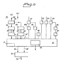
- a significant feature of the present invention resides in the particular design of the calculating circuit 51 and the manner in which it is adapted to evaluate and to calculate a hazard level, said calculated hazard level differing from the hazard-level-related value delivered by activated sensors.
- a number of output signals from activated sensors shall be delivered to the calculating circuit 51 and, in order to simplify the description, only output signals from the sensor 2 will be described. These signals may conveniently be co-ordinated with other output signals from other sensors 3.
- Output signals from other sensors may also be co-ordinated with output signals from other sensors.
- Hazard level-related output signals from the sensor 2 are delivered continuously to a memory 63 via a line 62.
- Current values can now be taken from the memory store via a circuit 64, these values being outputted on a line 65.
- a circuit 66 is adapted for evaluation of the first derivative of the received curve form, the value of this derivative appearing on a line 67.
- Calculated hazard level-related values on the lines 65 and 67 may be the subject of a weighting process in units 68, 69, where a high signal on the line 67 may be weighted to a greater extent than signals on the line 68 in certain applications.
- Each such weighting process may conveniently be effected through the medium of circuits in the calculating unit 51.
- a hazard level chosen by calculation on a line 70 may be changed by the evaluation of the calculating circuit 51 so as to enable the value of a hazard level, such as the hazard level A2, to be lowered when the value of the first derivative of the curve form increases.
- a threshold setting circuit 71 is thus not solely influenced by the curve form 64 applicable at that moment in time or the first derivative 66 of said curve form, but also by the choice of sensor detecting criteria where a current or immediate value 81, a rectified current value 81a and/or a detected rise in temperature 82 shall be given a higher priority than an increase in the carbon dioxide concentration, through the medium of the sensor 2.
- a factor that is dependent on the prevailing environment of the sensor 2 may be inserted through the medium of a circuit 84. In the case of a fire monitoring operation, this factor will have a lower value in the case of a moist environment than for a drier or an explosive environment.
- a circuit 85 that detects current temperature values and a circuit 86 for calculating the first derivative of temperature differences may also be connected to the calculating circuit 51 via weighted values in a unit 87. IR sensors may also be used.
- a memory store 88 sensor-detected variations deriving from a test in which a given gas is released from a chosen site or position and where the distribution rate, distribution values and the time-wise change in gas concentration are registered in said memory store as standard. Many such points may be evaluated so as to obtain a distribution pattern that can be stored in a memory.
- the measurement values obtained from the calculating circuits of each sensor and the time delay where significant changes can be noted, can now be used to determine the geographical location of the hazard situation.
- Figure 6 shows that a hazard level value 70 calculated in the calculating circuit 51 for the sensor 2 and the corresponding hazard level 70' for the sensor 3, and so on, shall be co-ordinated in a circuit 72 so as to provide by further calculation a hazard level value 73 which observes all measurement values, their changes in time, and different selected criteria.
- the geographical location of the hazard situation can now be calculated in the calculating unit 51.
- the time points t1, t2, t3 at which one and the same significant change occurs in the various sensors are entered into a circuit 90.
- the circuit 90 includes information relating to the spacing between said time points, information concerning prevailing wind or air speed and direction, and other information required for calculating the geographical position of the hazard situation.
Claims (16)
- System zum Evaluieren bzw. Auswerten der Entwicklung einer gefährlichen bzw. Gefahrensituation (6) innerhalb eines Raums oder eines Bereichs bzw. einer Fläche (1) mit der Hilfe von Gefahrenniveau-Konzepten bzw. Gefahrengrad-Konzepten und nach einem Auftreten einer gefährlichen Situation zum Ausbilden von Bedingungen, wodurch bzw. wobei das Gefahrenniveau bzw. der Gefahrengrad der gefährlichen Situation auf der Basis von Information betreffend die Entwicklung der gefährlichen Situation erhalten werden kann, die von einer Mehrzahl von Sensoren (2, 3) abgeleitet ist, welche in bezug auf im wesentlichen dieselben oder wechselweise unterschiedliche Kriterien funktionieren, daß Information betreffend die zeitabhängige Variation von Ausgangs- bzw. Ausgabesignalen, die sich auf die gefährliche Situation beziehen und von einem ersten Sensor (2) erhalten sind und auch auf die zeitabhängige Variation von ähnlichen Ausgabesignalen beziehen, die von einem zweiten Sensor (3) erhalten sind, gespeichert (63) werden können; daß ein Vergleich zwischen den momentanen Werten der Ausgabesignale und/oder gemessenen zeitabhängigen Änderungen einen Gefahrenniveauwert für das Auftreten einer gefährlichen Situation durch das Medium eines Berechnungsschaltkreises generiert; und daß lediglich die Gefahrenniveauwerte, die ein erstes Gefahrenniveau einer angezeigten gefährlichen Situation übersteigen, gewählt werden, um die Entwicklung der gefährlichen Situation mittels der Ausgabesignale von den Sensoren zu verfolgen, dadurch gekennzeichnet, daß ein berechnetes (66) Gefahrenniveau von einer signifikanten Änderung in der Variation des Ausgabesignals des ersten Sensors (2) in bezug auf die gefährliche Situation, einer signifikanten Änderung in der Variation des Ausgabesignals des zweiten Sensors (3) in bezug auf dieselbe gefährliche Situation, der Zeitdauer zwischen den signifikanten Änderungen und dem Abstand zwischen verwendeten Sensoren abhängig ist.
- System nach Anspruch 1, dadurch gekennzeichnet, daß der berechnete Gefahrenniveauwert gewählt werden soll, um ein erstes Gefahrenniveau zu übersteigen und unter einem zweiten Gefahrenniveau liegen soll.
- System nach Anspruch 1 oder 2, dadurch gekennzeichnet, daß, wenn der berechnete Gefahrenniveauwert ein zweites Gefahrenniveau übersteigt und unter einem dritten Gefahrenniveau liegt, die Entwicklung der Gefahr und/oder des Ereignisses weiters ausgewertet ist bzw. wird, und eine oder mehrere Maßnahmen von einer Mehrzahl von verfügbaren Maßnahmen auf der Basis dieser Auswertung durchgeführt bzw. ergriffen wird bzw. werden.
- System nach Anspruch 1 oder 2, dadurch gekennzeichnet, daß, wenn der berechnete Gefahrenniveauwert einen höchsten Wert eines dritten Gefahrenniveaus übersteigt, eine oder mehrere Tätigkeiten von einer Anzahl von verfügbaren Tätigkeiten ergriffen wird bzw. werden.
- System nach einem der Ansprüche 1 bis 4, dadurch gekennzeichnet, daß die Schwellwerte der Gefahrenniveaus in bezug auf gewählte-Kriterien und/oder eine gewählte Kombination von Kriterien adaptiert bzw. angepaßt sind bzw. werden.
- System nach Anspruch 1, dadurch gekennzeichnet, daß die zeitabhängige Variation von jedem Ausgabesignal in einem ersten Gefahrenniveau inhibiert bzw. verhindert ist bzw. wird, während jede zeitabhängige signifikante Änderung in einem zweiten Gefahrenniveau und über dem ersten Gefahrenniveau registriert und aufgezeichnet oder überwacht ist bzw. wird, um zu erlauben, daß die Entwicklung des Ereignisses oder der gefährlichen Situation bestimmt wird.
- System nach Anspruch 1, dadurch gekennzeichnet, daß die Schwellwerte der Gefahrenniveaus umgekehrt zu einem Wert der ersten Zeitableitung der Variation eingestellt bzw. angepaßt werden können.
- System nach Anspruch 1 oder 7, dadurch gekennzeichnet, daß die Schwellwerte der Gefahrenniveaus auf die Wahl eines Sensordetektionskriteriums und/oder mit einem Sensor assoziierten Umgebungen eingestellt bzw. angepaßt werden können.
- System nach Anspruch 1, dadurch gekennzeichnet, daß ein Kriterium der Wert oder die Größenordnung des Luftstroms in einem Raum in bezug auf die Geschwindigkeit und/oder die Richtung des Luftstroms und/oder eines Temperatur detektierenden Sensors ist.
- System nach Anspruch 1, dadurch gekennzeichnet, daß die Sensoren adaptiert sind, um die Konzentration von in der Luft transportierten Gasen, wie CO, CO2 und/oder anderen Gasen auszuwerten bzw. zu evaluieren.
- System nach einem der vorhergehenden Ansprüche, dadurch gekennzeichnet, daß die gewählten Sensoren mit einer Steuer- bzw. Regeleinheit verbunden sein sollen, wie einer Computereinrichtung; daß die Steuer- bzw. Regeleinheit beinhalten soll und/oder mit Speichervorrichtungen zusammenarbeiten soll, die adaptiert sind für die Speicherung von einem Sensor zugeordneten, auf Ausgabekriterien bezogenen, momentanen Werten in einer gewählten Zeitordnung bzw. -reihenfolge; und daß die Steuer- bzw. Regeleinheit beinhaltet und/oder damit verbunden eine Berechnungsschaltung aufweist, welche funktioniert, um zu erlauben, daß ein berechneter Gefahrenniveauwert auf der Basis von zeitabhängigen Änderungen in den evaluierten, mit einem Sensor assoziierten momentanen Werten zu evaluieren.
- System nach Anspruch 11, dadurch gekennzeichnet, daß mit der Steuer- bzw. Regeleinheit wenigstens ein Sensor verbunden ist, welcher adaptiert ist, um die Richtung und die Geschwindigkeit des Luftstroms in dem Raum zu evaluieren.
- System nach Anspruch 11 oder 12, dadurch gekennzeichnet, daß mit der Steuer- bzw. Regeleinheit wenigstens ein Sensor verbunden ist, der adaptiert ist für ein Bestimmen der Anwesenheit von IR-Strahlung.
- System nach Anspruch 11, 12 oder 13, dadurch gekennzeichnet, daß mit der Steuer- bzw. Regeleinheit wenigstens ein Wärmesensor oder ein Temperaturindikator verbunden ist.
- System nach einem der vorhergehenden Ansprüche, dadurch gekennzeichnet, daß die Werte der Gegenstand einer Berechnung mit der Verwendung von prioritätsabhängigen und wertgewichteten Mitteln ist.
- Anordnung zum Evaluieren der Entwicklung einer gefährlichen bzw. Gefahrensituation innerhalb eines Raums oder innerhalb eines Bereichs bzw. einer Fläche mit der Hilfe von Gefahrenniveaukonzepten und zum Erzeugen in dem Fall eines Auftretens von Gefahrensituationsbedingungen, welche es ermöglichen, daß das Gefahrenniveau der gefährlichen Situation auf der Basis von Information betreffend die Entwicklung der gefährlichen Situation bestimmt werden kann und die von einer Mehrzahl von Sensoren in bezug auf die zueinander selben oder zueinander unterschiedlichen Kriterien erhalten sind, dadurch gekennzeichnet, daß ein System gemäß einem der Ansprüche 1 bis 15 für ein Evaluieren der Information, die betreffend die zeitabhängige Variation der Ausgabesignale erhalten sind, die sich auf die Gefahrensituation bezieht, und von einem Sensor geliefert sind, und für ein Evaluieren von wenigstens einer zeitabhängigen Variation oder von ähnlichen Ausgabesignalen von einem zweiten Sensor zur Verfügung gestellt sind.
Applications Claiming Priority (3)
| Application Number | Priority Date | Filing Date | Title |
|---|---|---|---|
| SE0001094 | 2000-03-28 | ||
| SE0001094A SE520659C2 (sv) | 2000-03-28 | 2000-03-28 | Anordning och förfarande för att risknivåbestämma en risksituation |
| PCT/SE2001/000655 WO2001073716A1 (en) | 2000-03-28 | 2001-03-26 | A system and an arrangement to determine the level of hazard in a hazardous situation |
Publications (2)
| Publication Number | Publication Date |
|---|---|
| EP1290660A1 EP1290660A1 (de) | 2003-03-12 |
| EP1290660B1 true EP1290660B1 (de) | 2005-05-25 |
Family
ID=20279040
Family Applications (1)
| Application Number | Title | Priority Date | Filing Date |
|---|---|---|---|
| EP01918071A Expired - Lifetime EP1290660B1 (de) | 2000-03-28 | 2001-03-26 | System und anordnung zur bestimmung des gefahrengrads in einer gefährlichen situation |
Country Status (8)
| Country | Link |
|---|---|
| US (1) | US6867700B2 (de) |
| EP (1) | EP1290660B1 (de) |
| JP (1) | JP2003529168A (de) |
| AT (1) | ATE296474T1 (de) |
| AU (1) | AU2001244941A1 (de) |
| DE (1) | DE60111046T2 (de) |
| SE (1) | SE520659C2 (de) |
| WO (1) | WO2001073716A1 (de) |
Families Citing this family (6)
| Publication number | Priority date | Publication date | Assignee | Title |
|---|---|---|---|---|
| US6741951B2 (en) * | 2002-08-02 | 2004-05-25 | General Electric Company | Method for performing a hazard review and safety analysis of a product or system |
| WO2005124714A1 (en) * | 2004-06-22 | 2005-12-29 | Portendo Ab | Surveillance system for real-time threat monitoring |
| US7480536B2 (en) * | 2006-09-21 | 2009-01-20 | General Electric Company | Method for assessing reliability requirements of a safety instrumented control function |
| WO2010135567A2 (en) * | 2009-05-20 | 2010-11-25 | Baker Engineering And Risk Consultants, Inc. | System and method for hazardous area classification |
| US9361810B2 (en) | 2012-03-30 | 2016-06-07 | Pegasus Global Strategic Solutions Llc | Uninhabited test city |
| CN113781887B (zh) * | 2021-10-25 | 2023-04-04 | 国网江苏省电力有限公司电力科学研究院 | 一种基于集装箱式电缆隧道的火情反演模拟分析系统 |
Family Cites Families (15)
| Publication number | Priority date | Publication date | Assignee | Title |
|---|---|---|---|---|
| JPS5977594A (ja) | 1982-10-27 | 1984-05-04 | ニツタン株式会社 | 火災警報システム |
| DE68926958T2 (de) * | 1988-12-02 | 1997-04-03 | Nohmi Bosai Ltd | Feueralarmsystem |
| US5670938A (en) | 1991-01-18 | 1997-09-23 | Hochiki Kabushiki Kaisha | Fire alarm device |
| FI916182A (fi) | 1991-01-18 | 1992-07-19 | Hochiki Co | Kombinerad metod foer faststaellande av brand. |
| US6501810B1 (en) * | 1998-10-13 | 2002-12-31 | Agere Systems Inc. | Fast frame synchronization |
| JP3274929B2 (ja) | 1994-03-30 | 2002-04-15 | 能美防災株式会社 | 初期火災検出装置 |
| US6064064A (en) * | 1996-03-01 | 2000-05-16 | Fire Sentry Corporation | Fire detector |
| US5818326A (en) * | 1996-07-02 | 1998-10-06 | Simplex Time Recorder Company | Early fire detection using temperature and smoke sensing |
| US5895445A (en) * | 1997-04-22 | 1999-04-20 | Daewoo Telecom Ltd. | Method for managing facilities and workers within a closed range |
| US6215405B1 (en) * | 1998-04-23 | 2001-04-10 | Digital Security Controls Ltd. | Programmable temperature sensor for security system |
| JP3487776B2 (ja) * | 1998-11-30 | 2004-01-19 | ホーチキ株式会社 | 火災感知設備における感知情報表示システム |
| US6420973B2 (en) * | 1999-01-23 | 2002-07-16 | James Acevedo | Wireless smoke detection system |
| US6320501B1 (en) * | 1999-05-25 | 2001-11-20 | Pittway Corporation | Multiple sensor system for alarm determination with device-to-device communications |
| US6346880B1 (en) * | 1999-12-20 | 2002-02-12 | Motorola, Inc. | Circuit and method for controlling an alarm |
| US6166647A (en) * | 2000-01-18 | 2000-12-26 | Jaesent Inc. | Fire detector |
-
2000
- 2000-03-28 SE SE0001094A patent/SE520659C2/sv not_active IP Right Cessation
-
2001
- 2001-03-26 DE DE60111046T patent/DE60111046T2/de not_active Expired - Lifetime
- 2001-03-26 AT AT01918071T patent/ATE296474T1/de not_active IP Right Cessation
- 2001-03-26 AU AU2001244941A patent/AU2001244941A1/en not_active Abandoned
- 2001-03-26 JP JP2001571358A patent/JP2003529168A/ja active Pending
- 2001-03-26 EP EP01918071A patent/EP1290660B1/de not_active Expired - Lifetime
- 2001-03-26 WO PCT/SE2001/000655 patent/WO2001073716A1/en active IP Right Grant
- 2001-03-26 US US10/239,762 patent/US6867700B2/en not_active Expired - Lifetime
Also Published As
| Publication number | Publication date |
|---|---|
| DE60111046T2 (de) | 2006-05-04 |
| SE520659C2 (sv) | 2003-08-05 |
| WO2001073716A1 (en) | 2001-10-04 |
| SE0001094L (sv) | 2001-09-29 |
| AU2001244941A1 (en) | 2001-10-08 |
| EP1290660A1 (de) | 2003-03-12 |
| JP2003529168A (ja) | 2003-09-30 |
| US6867700B2 (en) | 2005-03-15 |
| US20030058103A1 (en) | 2003-03-27 |
| ATE296474T1 (de) | 2005-06-15 |
| DE60111046D1 (de) | 2005-06-30 |
| WO2001073716A9 (en) | 2001-12-20 |
| SE0001094D0 (sv) | 2000-03-28 |
Similar Documents
| Publication | Publication Date | Title |
|---|---|---|
| EP1281167B1 (de) | System und anordnung zur bestimmung der position in einer gefährlichen situation | |
| US8542115B2 (en) | Environmental sensor with webserver and email notification | |
| KR100696740B1 (ko) | 화재경보장치 및 화재경보시스템 | |
| US5483222A (en) | Multiple sensor apparatus and method | |
| KR101478691B1 (ko) | 인텔리전트 빌딩의 화재 확산 지연 시스템 및 방법 | |
| US20130120137A1 (en) | Person-guiding system for evacuating a building or a building section | |
| US10885763B2 (en) | Sensing technologies in alarm devices | |
| KR20150080127A (ko) | 화재 예방 시스템 및 방법 | |
| KR102275994B1 (ko) | 비화재보를 예방할 수 있는 화재감지 시스템 | |
| EP1290660B1 (de) | System und anordnung zur bestimmung des gefahrengrads in einer gefährlichen situation | |
| KR102103786B1 (ko) | 지능형 화재 대피 유도시스템 | |
| JP6964030B2 (ja) | 監視システム及び監視方法 | |
| KR101447718B1 (ko) | 강우 강도와 기간 강우량 분석을 통한 강우 경보 장치 및 강우 경보 생성 방법 | |
| JPH02136793A (ja) | プラント異常点検装置 | |
| JP3034972B2 (ja) | 自火報システムの判定感度設定方法 | |
| JP2004110371A (ja) | 火災フェイズ管理装置、及び火災フェイズ管理方法 | |
| KR101817341B1 (ko) | 엘리베이터를 이용한 건물 소방환경 모니터링 시스템 | |
| TWI680000B (zh) | 依據消防設備位置啟動火場周圍消防設備之系統及方法 | |
| JPH01312699A (ja) | 避難経路表示システム | |
| CN117975642A (zh) | 一种消防设施智能管理系统 | |
| CN111354149A (zh) | 一种基于物联网的火灾报警方法、报警装置及存储介质 | |
| JP2003187362A (ja) | 発電所・工場等における避難誘導システム | |
| JPH02220196A (ja) | 火災感知装置 | |
| JPS6086694A (ja) | 遠隔監視装置 |
Legal Events
| Date | Code | Title | Description |
|---|---|---|---|
| PUAI | Public reference made under article 153(3) epc to a published international application that has entered the european phase |
Free format text: ORIGINAL CODE: 0009012 |
|
| 17P | Request for examination filed |
Effective date: 20021028 |
|
| AK | Designated contracting states |
Kind code of ref document: A1 Designated state(s): AT BE CH CY DE DK ES FI FR GB GR IE IT LI LU MC NL PT SE TR |
|
| AX | Request for extension of the european patent |
Extension state: AL LT LV MK RO SI |
|
| 17Q | First examination report despatched |
Effective date: 20040210 |
|
| GRAP | Despatch of communication of intention to grant a patent |
Free format text: ORIGINAL CODE: EPIDOSNIGR1 |
|
| GRAS | Grant fee paid |
Free format text: ORIGINAL CODE: EPIDOSNIGR3 |
|
| GRAA | (expected) grant |
Free format text: ORIGINAL CODE: 0009210 |
|
| AK | Designated contracting states |
Kind code of ref document: B1 Designated state(s): AT BE CH CY DE DK ES FI FR GB GR IE IT LI LU MC NL PT SE TR |
|
| PG25 | Lapsed in a contracting state [announced via postgrant information from national office to epo] |
Ref country code: TR Free format text: LAPSE BECAUSE OF FAILURE TO SUBMIT A TRANSLATION OF THE DESCRIPTION OR TO PAY THE FEE WITHIN THE PRESCRIBED TIME-LIMIT Effective date: 20050525 Ref country code: NL Free format text: LAPSE BECAUSE OF FAILURE TO SUBMIT A TRANSLATION OF THE DESCRIPTION OR TO PAY THE FEE WITHIN THE PRESCRIBED TIME-LIMIT Effective date: 20050525 Ref country code: AT Free format text: LAPSE BECAUSE OF FAILURE TO SUBMIT A TRANSLATION OF THE DESCRIPTION OR TO PAY THE FEE WITHIN THE PRESCRIBED TIME-LIMIT Effective date: 20050525 Ref country code: FI Free format text: LAPSE BECAUSE OF FAILURE TO SUBMIT A TRANSLATION OF THE DESCRIPTION OR TO PAY THE FEE WITHIN THE PRESCRIBED TIME-LIMIT Effective date: 20050525 Ref country code: LI Free format text: LAPSE BECAUSE OF FAILURE TO SUBMIT A TRANSLATION OF THE DESCRIPTION OR TO PAY THE FEE WITHIN THE PRESCRIBED TIME-LIMIT Effective date: 20050525 Ref country code: BE Free format text: LAPSE BECAUSE OF FAILURE TO SUBMIT A TRANSLATION OF THE DESCRIPTION OR TO PAY THE FEE WITHIN THE PRESCRIBED TIME-LIMIT Effective date: 20050525 Ref country code: CH Free format text: LAPSE BECAUSE OF FAILURE TO SUBMIT A TRANSLATION OF THE DESCRIPTION OR TO PAY THE FEE WITHIN THE PRESCRIBED TIME-LIMIT Effective date: 20050525 |
|
| REG | Reference to a national code |
Ref country code: GB Ref legal event code: FG4D |
|
| REG | Reference to a national code |
Ref country code: CH Ref legal event code: EP |
|
| REG | Reference to a national code |
Ref country code: IE Ref legal event code: FG4D |
|
| REF | Corresponds to: |
Ref document number: 60111046 Country of ref document: DE Date of ref document: 20050630 Kind code of ref document: P |
|
| PG25 | Lapsed in a contracting state [announced via postgrant information from national office to epo] |
Ref country code: DK Free format text: LAPSE BECAUSE OF FAILURE TO SUBMIT A TRANSLATION OF THE DESCRIPTION OR TO PAY THE FEE WITHIN THE PRESCRIBED TIME-LIMIT Effective date: 20050825 Ref country code: SE Free format text: LAPSE BECAUSE OF FAILURE TO SUBMIT A TRANSLATION OF THE DESCRIPTION OR TO PAY THE FEE WITHIN THE PRESCRIBED TIME-LIMIT Effective date: 20050825 Ref country code: GR Free format text: LAPSE BECAUSE OF FAILURE TO SUBMIT A TRANSLATION OF THE DESCRIPTION OR TO PAY THE FEE WITHIN THE PRESCRIBED TIME-LIMIT Effective date: 20050825 |
|
| PG25 | Lapsed in a contracting state [announced via postgrant information from national office to epo] |
Ref country code: PT Free format text: LAPSE BECAUSE OF FAILURE TO SUBMIT A TRANSLATION OF THE DESCRIPTION OR TO PAY THE FEE WITHIN THE PRESCRIBED TIME-LIMIT Effective date: 20051027 |
|
| REG | Reference to a national code |
Ref country code: CH Ref legal event code: PL |
|
| NLV1 | Nl: lapsed or annulled due to failure to fulfill the requirements of art. 29p and 29m of the patents act | ||
| PG25 | Lapsed in a contracting state [announced via postgrant information from national office to epo] |
Ref country code: IE Free format text: LAPSE BECAUSE OF NON-PAYMENT OF DUE FEES Effective date: 20060327 |
|
| PG25 | Lapsed in a contracting state [announced via postgrant information from national office to epo] |
Ref country code: LU Free format text: LAPSE BECAUSE OF NON-PAYMENT OF DUE FEES Effective date: 20060331 Ref country code: MC Free format text: LAPSE BECAUSE OF NON-PAYMENT OF DUE FEES Effective date: 20060331 |
|
| PLBE | No opposition filed within time limit |
Free format text: ORIGINAL CODE: 0009261 |
|
| STAA | Information on the status of an ep patent application or granted ep patent |
Free format text: STATUS: NO OPPOSITION FILED WITHIN TIME LIMIT |
|
| ET | Fr: translation filed | ||
| 26N | No opposition filed |
Effective date: 20060228 |
|
| REG | Reference to a national code |
Ref country code: IE Ref legal event code: MM4A |
|
| PG25 | Lapsed in a contracting state [announced via postgrant information from national office to epo] |
Ref country code: CY Free format text: LAPSE BECAUSE OF FAILURE TO SUBMIT A TRANSLATION OF THE DESCRIPTION OR TO PAY THE FEE WITHIN THE PRESCRIBED TIME-LIMIT Effective date: 20050525 |
|
| PG25 | Lapsed in a contracting state [announced via postgrant information from national office to epo] |
Ref country code: ES Free format text: LAPSE BECAUSE OF NON-PAYMENT OF DUE FEES Effective date: 20060331 |
|
| REG | Reference to a national code |
Ref country code: FR Ref legal event code: PLFP Year of fee payment: 16 |
|
| REG | Reference to a national code |
Ref country code: FR Ref legal event code: PLFP Year of fee payment: 17 |
|
| REG | Reference to a national code |
Ref country code: FR Ref legal event code: PLFP Year of fee payment: 18 |
|
| PGFP | Annual fee paid to national office [announced via postgrant information from national office to epo] |
Ref country code: GB Payment date: 20200318 Year of fee payment: 20 Ref country code: DE Payment date: 20200319 Year of fee payment: 20 Ref country code: IT Payment date: 20200319 Year of fee payment: 20 |
|
| PGFP | Annual fee paid to national office [announced via postgrant information from national office to epo] |
Ref country code: FR Payment date: 20200313 Year of fee payment: 20 |
|
| REG | Reference to a national code |
Ref country code: DE Ref legal event code: R071 Ref document number: 60111046 Country of ref document: DE |
|
| REG | Reference to a national code |
Ref country code: GB Ref legal event code: PE20 Expiry date: 20210325 |
|
| PG25 | Lapsed in a contracting state [announced via postgrant information from national office to epo] |
Ref country code: GB Free format text: LAPSE BECAUSE OF EXPIRATION OF PROTECTION Effective date: 20210325 |