EP1289872B1 - Vorrichtung und verfahren zum transportieren von leichten bauplatten - Google Patents
Vorrichtung und verfahren zum transportieren von leichten bauplatten Download PDFInfo
- Publication number
- EP1289872B1 EP1289872B1 EP01900298A EP01900298A EP1289872B1 EP 1289872 B1 EP1289872 B1 EP 1289872B1 EP 01900298 A EP01900298 A EP 01900298A EP 01900298 A EP01900298 A EP 01900298A EP 1289872 B1 EP1289872 B1 EP 1289872B1
- Authority
- EP
- European Patent Office
- Prior art keywords
- transport
- light building
- gripping
- building panel
- cover
- Prior art date
- Legal status (The legal status is an assumption and is not a legal conclusion. Google has not performed a legal analysis and makes no representation as to the accuracy of the status listed.)
- Expired - Lifetime
Links
- 238000010276 construction Methods 0.000 claims abstract 2
- 230000001419 dependent effect Effects 0.000 claims 1
- 238000000034 method Methods 0.000 abstract description 9
- 238000004040 coloring Methods 0.000 abstract description 3
- 238000009413 insulation Methods 0.000 description 3
- RYGMFSIKBFXOCR-UHFFFAOYSA-N Copper Chemical compound [Cu] RYGMFSIKBFXOCR-UHFFFAOYSA-N 0.000 description 1
- 229910000831 Steel Inorganic materials 0.000 description 1
- 229910052782 aluminium Inorganic materials 0.000 description 1
- XAGFODPZIPBFFR-UHFFFAOYSA-N aluminium Chemical compound [Al] XAGFODPZIPBFFR-UHFFFAOYSA-N 0.000 description 1
- 238000013459 approach Methods 0.000 description 1
- 229910052802 copper Inorganic materials 0.000 description 1
- 239000010949 copper Substances 0.000 description 1
- 230000003247 decreasing effect Effects 0.000 description 1
- 238000004519 manufacturing process Methods 0.000 description 1
- 239000000463 material Substances 0.000 description 1
- 229910052751 metal Inorganic materials 0.000 description 1
- 239000002184 metal Substances 0.000 description 1
- 229920003023 plastic Polymers 0.000 description 1
- 239000004033 plastic Substances 0.000 description 1
- 230000003014 reinforcing effect Effects 0.000 description 1
- 239000007779 soft material Substances 0.000 description 1
- 239000007787 solid Substances 0.000 description 1
- 239000010959 steel Substances 0.000 description 1
Images


Classifications
-
- B—PERFORMING OPERATIONS; TRANSPORTING
- B66—HOISTING; LIFTING; HAULING
- B66C—CRANES; LOAD-ENGAGING ELEMENTS OR DEVICES FOR CRANES, CAPSTANS, WINCHES, OR TACKLES
- B66C1/00—Load-engaging elements or devices attached to lifting or lowering gear of cranes or adapted for connection therewith for transmitting lifting forces to articles or groups of articles
- B66C1/10—Load-engaging elements or devices attached to lifting or lowering gear of cranes or adapted for connection therewith for transmitting lifting forces to articles or groups of articles by mechanical means
- B66C1/42—Gripping members engaging only the external or internal surfaces of the articles
- B66C1/44—Gripping members engaging only the external or internal surfaces of the articles and applying frictional forces
- B66C1/54—Internally-expanding grippers for handling hollow articles
Definitions
- the invention relates to the problem of manufacturing for transport and method for transport of light building panels or similar elements, said elements comprised of filling (core) and a shell and are at least on one side designed in such a fashion as to enable overlap of panels.
- the solution addresses the problem of mechanical characteristics and possible damage of shell coloring to prevent damage to shell and to its cover during the transport.
- patent document DE 1.756,606 discloses a device for transport of light building panel comprising of a housing, at least one gripping element, and at least one connecting means element to connect the gripping element to the housing, wherein the gripping element comprises a hook, said hook used to engage the light building panel, and a longer leg (upper part of the gripping element 5 or 6), said longer leg used to connect the gripping element to the housing.
- the subject of new invention is Device and method for transport of light building panels procedure and is solving above described technical problem whereby the invention takes mostly advantage of shape-wise attachment of building panel onto the transporter.
- the method enables attachment at one, two or several points whereby the gripping elements are of arbitrary length, hence the specific load on the building panel is continuous rather than pointwise which reduces possibility of structural damage and damage of the color.
- the gripping elements attach to edges of outer and inner layer of the shell from within so there should be no visible tracks of attachment following the transport.
- Light building panels are building elements and are used for facades and roofs. They typically comprise outer layer and inner layer giving the panel form, and filling giving the panel insulation capabilities and appropriate strength.
- the device for transport of light building panels is comprised of at least one attachment head which attaches to the light building panel.
- Each attachment head is comprised of a cover, a hanging element, and at least one gripping element.
- the cover and the hanging elements comprise a housing of the attachment head.
- the gripping element is positioned under folded edges of the panel, fixed in the position relative to the panel, and used for transport of panel using the following algorithm:
- At least one gripping element with the cover and the hanging element form single element which provides for appropriate force exerted on the panel via principle of the lever during elevation and transport of the panel.
- the actual level of force is connected to weight of the panel - heavier the panel larger the force.
- the cover and the gripping element are formed in such a fashion that they fix the edge of the panel between them when ready for transport.
- the hanging element is connected to the cover via flexible (rotatable) connecting element. It connects all parts of the device into single rigid device.
- the flexible connecting element may be manufactured in such a fashion that a distance between a center of the auxiliary pin (6) and a center of the pin (7) is smaller than a distance between the center of the pin (7) and the center of a hole or other attaching means to attach attachment head to a crane's cable or some other form of transporting device. If such a case the lever mechanism provides for appropriate force exerted between the cover and the gripping element.
- the gripping element or plurality thereof may be of various length. They are inserted through the cover and may be of such design that they cannot be separated from the cover and the hanging element.
- the upper leg of the gripping element should be long enough to provide for easy enough handling (due to use of principle of the lever) with hands and without tools or accessories not usually found on the building site.
- the material of the top layer (the shell) of the light building panels (2) can be different, from steel sheet, aluminum, copper, or other metal sheet to plastics. It must provide for suitable mechanical properties, particularly in part of the shell which attaches to the attachment head which attaches to the folded edge of the panel. Should the shell be made of brittle or soft material the edge can be manufactured using double or multiple folded edge of the shell or with adding of reinforcing elements which further distribute the load arising of attachment across larger area hence reducing the stress in the shell.
- the attachment head is positioned onto the attaching edge of the panel.
- the cover (3) of the attachment head is positioned on the top of attaching side of the panel.
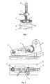
- the hooks of the gripping elements (4) are positioned underneath the edges of the attaching side (as presented in the figure 3) which requires appropriate design of the core (1) and the shell (2) of the light building panel. The design must allow for positioning of the hooks of the gripping elements and process of locking and unlocking.
- the hooks are extending more and more underneath the edges while the longer legs (as opposed to the shorter legs which are also known as hooks for purposes of this application) of the gripping elements (4) are closing in and the hooks engage the panel.
- the gripping elements (4) which are two in this embodiment are in their final position, in this embodiment in essentially vertical position they should be locked in this position and at the same time hanged using the hanging element (5) and secured using pin (7).
- the pin (7) extends through both longer legs of the gripping elements and through the hanging element (5).
- the hanging element (5) clasps (hugs) around both gripping elements (figure 2).
- the hanging element (5) closes (locks) by rotating around the center the rotation which is signified by auxiliary pin (6). By rotating the hanging element (5) clasps around both longer legs of the gripping elements (4) or plurality thereof.
- the hanging and gripping elements are connected to each other by pin (7).
- the pin (7) may also feature security element against pin falling out.
- the cover (3) and the gripping element (4) are designed to clutch the edges of the attaching between the cover and respective hook of the gripping element (4) thereby providing for solid connection between attaching head and the panel.
- the transport is performed using two attachment heads as presented in figure 5, however this does not exclude possibility to perform the transport with a single or multiple attachment heads.
Landscapes
- Engineering & Computer Science (AREA)
- Mechanical Engineering (AREA)
- Conveying And Assembling Of Building Elements In Situ (AREA)
- Laminated Bodies (AREA)
- Securing Of Glass Panes Or The Like (AREA)
- Container Filling Or Packaging Operations (AREA)
Claims (8)
- Vorrichtung für den Transport einer Leichtbauplatte, die einen Kern (1) und eine Schale (2) mit gefalteten Rändern an ihrer Halterungsseite, wobei diese Vorrichtung eine Abdeckung (3), die an der Oberseite der Halterungsoberseite der Leichtbauplatte positionierbar ist, mindestens ein Greiferelement (4) mit einem Haken, der unter den Rändern der Leichtbauplatte positionierbar ist, und mindestens ein Hängeelement (5) aufweist, das an einer Transportvorrichtung anbringbar ist, wobei diese Greifer-(4) und Hängeelemente (5) unter Verwendung einer Verbindungseinrichtung (7) miteinander verbunden sind, dadurch gekennzeichnet, daß dieses Hängeelement (5) drehbar an dieser Abdeckung (3) angeschlossen ist, und daß diese Verbindungseinrichtung (7) dieses Hängeelement mit diesem mindestens einen Greiferelement (4) verriegeln kann, derart, daß dieses mindestens eine Greiferelement (4) und diese Abdeckung (3) die Ränder der Schale der Leichtbauplatte ergreifen können.
- Vorrichtung für den Transport einer Leichtbauplatte nach Anspruch 1, dadurch gekennzeichnet, daß sie mindestens zwei Greiferelemente (4) aufweist und in der Lage ist, jedes Greiferelement (4) zu positionieren, um einen Haken unter eine Falte zu verstellen, die einen Rand der Leichtbauplattenschale bildet, wobei diese Greiferelemente (4) in einer solchen Weise positioniert sind, daß Haken von jedem benachbarten Greiferelement (4) sich im wesentlichen kollinear aber in entgegengesetzter Richtung erstrecken, wobei jedes dieser Greiferelemente (4) sich um ein virtuelles Rotationszentrum dreht, bis längere Schenkel dieser Greiferelemente gegeneinander zur Anlage kommen, wobei diese Greiferelemente mit der Verbindungseinrichtung verriegelt werden.
- Vorrichtung für den Transport einer Leichtbauplatte gemäß einem der vorhergehenden Ansprüche, dadurch gekennzeichnet, daß die Verbindungseinrichtung mindestens einen Zapfen (7) aufweist, und daß dieser Zapfen (7) als Verbindung zwischen diesem Hängeelement (5) und mindestens einem Greiferelement (4) dient.
- Vorrichtung für den Transport einer Leichtbauplatte gemäß einem der vorhergehenden Ansprüche, dadurch gekennzeichnet, daß das Hängeelement (5) frei drehbar um einen Hilfszapfen (6) ist und sich, wenn verriegelt, um mindestens ein Greiferelement (4) erstreckt.
- Vorrichtung für den Transport einer Leichtbauplatte gemäß einem der vorhergehenden Ansprüche, dadurch gekennzeichnet daß das Greiferelement (4) durch die Abdeckung (3) angebracht ist, daß die Abdeckung (3) derart kontruiert ist, daß, sobald montiert, daß Greiferelement (4) nicht zerstörungsfrei von der Abdeckung (3) und dem Hängeelement (5) getrennt werden kann und eine Einheit mit der Abdeckung (3) und dem Hängeelement (5) bildet.
- Vorrichtung für den Transport einer Leichtbauplatte nach einem der vorhergehenden Ansprüche, dadurch gekennzeichnet, daß das Greiferelement (4) einen oberen Schenkel aufweist, der lang genug ist, daß das Greiferelement (4) in die für das Verriegeln fertige Endposition verschwenkt werden kann, indem die Kraft eines durchschnittlichen Bauhandwerkers ohne zusätzliche Werkzeuge oder Ausrüstung verwendet wird.
- Vorrichtung für den Transport einer Leichtbauplatte nach einem der vorhergehenden Ansprüche, dadurch gekennzeichnet, daß das Greiferelement (4) eine Einheit mit der Abdeckung (3) und dem Hängeelement (5) bildet, und daß diese Einheit unter Zunutzemachung eines Hebelmechanismus während des Transports Kraft auf die Platte ausübt, wobei diese Kraft mit erhöhtem Gewicht der transportierten Platte größer wird.
- Vorrichtung für den Transport einer Leichtbauplatte nach Anspruch 4 oder einem der Ansprüche 5 bis 7 sofern abhängig von Anspruch 4, dadurch gekennzeichnet, daß die frei drehbare Verbindung um den Hilfszapfen (6) in einer solchen Weise konstruiert ist, daß ein Abstand zwischen dem Zentrum dieses Hilfszapfens (6) und dem Zapfen (7) kleiner ist als ein Abstand zwischen dem Zentrum des Zapfens (7) und einer Öffnung in dem Hängeelement (5) die benutzt wird zur Befestigung der Einheit an der Transportvorrichtung.
Applications Claiming Priority (3)
| Application Number | Priority Date | Filing Date | Title |
|---|---|---|---|
| SI200000094 | 2000-04-07 | ||
| SI200000094A SI20541B (sl) | 2000-04-07 | 2000-04-07 | Naprava in postopek za prenašanje lahkih gradbenih plošč med montažo |
| PCT/SI2001/000002 WO2001076999A1 (en) | 2000-04-07 | 2001-01-08 | Transport of light building panels |
Publications (2)
| Publication Number | Publication Date |
|---|---|
| EP1289872A1 EP1289872A1 (de) | 2003-03-12 |
| EP1289872B1 true EP1289872B1 (de) | 2005-10-12 |
Family
ID=20432639
Family Applications (1)
| Application Number | Title | Priority Date | Filing Date |
|---|---|---|---|
| EP01900298A Expired - Lifetime EP1289872B1 (de) | 2000-04-07 | 2001-01-08 | Vorrichtung und verfahren zum transportieren von leichten bauplatten |
Country Status (6)
| Country | Link |
|---|---|
| EP (1) | EP1289872B1 (de) |
| AT (1) | ATE306456T1 (de) |
| AU (1) | AU2421501A (de) |
| DE (1) | DE60120153T2 (de) |
| SI (1) | SI20541B (de) |
| WO (1) | WO2001076999A1 (de) |
Families Citing this family (2)
| Publication number | Priority date | Publication date | Assignee | Title |
|---|---|---|---|---|
| FI116462B (fi) * | 2002-12-03 | 2005-11-30 | Paroc Group Oy Ab | Nostolaite |
| CN112479020A (zh) * | 2020-12-30 | 2021-03-12 | 山东万事达建筑钢品股份有限公司 | 一种夹芯板专用吊装工具 |
Family Cites Families (3)
| Publication number | Priority date | Publication date | Assignee | Title |
|---|---|---|---|---|
| DE2523816C3 (de) * | 1975-05-29 | 1980-12-18 | Erich 1000 Berlin Wegner | In eine öffnung einsetz· und dort verriegelbarer Lasthebeanker |
| FI89473C (fi) * | 1992-04-06 | 1993-10-11 | Paroc Oy Ab | Lyftanordning och -foerfarande |
| DE19510004A1 (de) * | 1995-03-23 | 1996-09-26 | Winden Und Maschinenbau Gresba | Gerät zum Ergreifen und Handhaben von Kanalschacht-Konen |
-
2000
- 2000-04-07 SI SI200000094A patent/SI20541B/sl active Search and Examination
-
2001
- 2001-01-08 AT AT01900298T patent/ATE306456T1/de not_active IP Right Cessation
- 2001-01-08 WO PCT/SI2001/000002 patent/WO2001076999A1/en not_active Ceased
- 2001-01-08 EP EP01900298A patent/EP1289872B1/de not_active Expired - Lifetime
- 2001-01-08 AU AU24215/01A patent/AU2421501A/en not_active Abandoned
- 2001-01-08 DE DE60120153T patent/DE60120153T2/de not_active Expired - Lifetime
Also Published As
| Publication number | Publication date |
|---|---|
| SI20541B (sl) | 2009-12-31 |
| AU2421501A (en) | 2001-10-23 |
| WO2001076999A1 (en) | 2001-10-18 |
| EP1289872A1 (de) | 2003-03-12 |
| SI20541A (sl) | 2001-10-31 |
| DE60120153T2 (de) | 2006-09-28 |
| DE60120153D1 (de) | 2006-07-06 |
| ATE306456T1 (de) | 2005-10-15 |
Similar Documents
| Publication | Publication Date | Title |
|---|---|---|
| US5444946A (en) | Portable shelter assemblies | |
| US11199110B2 (en) | Thrust reverser cowl rack | |
| JP5485916B2 (ja) | 工具で操作する溝式ラッチ | |
| EP3943794B1 (de) | Umkehrbare klammer | |
| US20030116983A1 (en) | Collapsible grappling hook | |
| US6334590B1 (en) | Removable hoist for aircraft | |
| US9120572B2 (en) | Aircraft crew cabin changing area | |
| GB2034398A (en) | Closure device for container doors | |
| EP1289872A1 (de) | Vorrichtung und verfahren zum transportieren von leichten bauplatten | |
| US20050186033A1 (en) | Apparatus and method | |
| US4817401A (en) | Retaining barrier assembly | |
| CN209942720U (zh) | 便携式梯子 | |
| US6966534B2 (en) | Wire system for hanging picture frames | |
| WO2010029209A1 (es) | Procedimiento para el transporte, manipulación, posicionado y fijación de elementos constructivos prefabricados de suelo a techo para conformar paredes o tabiques interiores resistentes al fuego en toda clase de construcciones, incluida la construcción naval | |
| JP3978274B2 (ja) | 固定具 | |
| JP4227774B2 (ja) | 天蓋開閉装置付コンテナ | |
| CN216190284U (zh) | 一种用于建筑材料吊运的紧固装置 | |
| US4631863A (en) | Door or window guard system | |
| WO2021089998A1 (en) | Anchor device | |
| KR200200195Y1 (ko) | 크레인용 걸고리 | |
| JP2500475B2 (ja) | クイックリリ―ス付き吊り金具接続機構 | |
| EP1138626A2 (de) | Verfahren und Vorrichtung zum Heben eines Gegenstandes | |
| US20250325132A1 (en) | Secure device for package delivery | |
| JPS5832158B2 (ja) | パンタグラフシキアタツチメントノ ラチエツトキコウ | |
| JP3125728B2 (ja) | パネルロック機構 |
Legal Events
| Date | Code | Title | Description |
|---|---|---|---|
| PUAI | Public reference made under article 153(3) epc to a published international application that has entered the european phase |
Free format text: ORIGINAL CODE: 0009012 |
|
| 17P | Request for examination filed |
Effective date: 20021107 |
|
| AK | Designated contracting states |
Kind code of ref document: A1 Designated state(s): AT BE CH CY DE DK ES FI FR GB GR IE IT LI LU MC NL PT SE TR |
|
| AX | Request for extension of the european patent |
Extension state: AL LT LV MK RO SI |
|
| 17Q | First examination report despatched |
Effective date: 20040305 |
|
| GRAP | Despatch of communication of intention to grant a patent |
Free format text: ORIGINAL CODE: EPIDOSNIGR1 |
|
| GRAS | Grant fee paid |
Free format text: ORIGINAL CODE: EPIDOSNIGR3 |
|
| GRAA | (expected) grant |
Free format text: ORIGINAL CODE: 0009210 |
|
| AK | Designated contracting states |
Kind code of ref document: B1 Designated state(s): AT BE CH CY DE DK ES FI FR GB GR IE IT LI LU MC NL PT SE TR |
|
| PG25 | Lapsed in a contracting state [announced via postgrant information from national office to epo] |
Ref country code: IT Free format text: LAPSE BECAUSE OF FAILURE TO SUBMIT A TRANSLATION OF THE DESCRIPTION OR TO PAY THE FEE WITHIN THE PRESCRIBED TIME-LIMIT;WARNING: LAPSES OF ITALIAN PATENTS WITH EFFECTIVE DATE BEFORE 2007 MAY HAVE OCCURRED AT ANY TIME BEFORE 2007. THE CORRECT EFFECTIVE DATE MAY BE DIFFERENT FROM THE ONE RECORDED. Effective date: 20051012 Ref country code: NL Free format text: LAPSE BECAUSE OF FAILURE TO SUBMIT A TRANSLATION OF THE DESCRIPTION OR TO PAY THE FEE WITHIN THE PRESCRIBED TIME-LIMIT Effective date: 20051012 Ref country code: LI Free format text: LAPSE BECAUSE OF FAILURE TO SUBMIT A TRANSLATION OF THE DESCRIPTION OR TO PAY THE FEE WITHIN THE PRESCRIBED TIME-LIMIT Effective date: 20051012 Ref country code: FI Free format text: LAPSE BECAUSE OF FAILURE TO SUBMIT A TRANSLATION OF THE DESCRIPTION OR TO PAY THE FEE WITHIN THE PRESCRIBED TIME-LIMIT Effective date: 20051012 Ref country code: AT Free format text: LAPSE BECAUSE OF FAILURE TO SUBMIT A TRANSLATION OF THE DESCRIPTION OR TO PAY THE FEE WITHIN THE PRESCRIBED TIME-LIMIT Effective date: 20051012 Ref country code: CH Free format text: LAPSE BECAUSE OF FAILURE TO SUBMIT A TRANSLATION OF THE DESCRIPTION OR TO PAY THE FEE WITHIN THE PRESCRIBED TIME-LIMIT Effective date: 20051012 Ref country code: BE Free format text: LAPSE BECAUSE OF FAILURE TO SUBMIT A TRANSLATION OF THE DESCRIPTION OR TO PAY THE FEE WITHIN THE PRESCRIBED TIME-LIMIT Effective date: 20051012 |
|
| REG | Reference to a national code |
Ref country code: GB Ref legal event code: FG4D |
|
| RIN1 | Information on inventor provided before grant (corrected) |
Inventor name: NOVAK, ANDREJ Inventor name: TISU, BRANKO; |
|
| REG | Reference to a national code |
Ref country code: CH Ref legal event code: EP |
|
| REG | Reference to a national code |
Ref country code: IE Ref legal event code: FG4D |
|
| PG25 | Lapsed in a contracting state [announced via postgrant information from national office to epo] |
Ref country code: IE Free format text: LAPSE BECAUSE OF NON-PAYMENT OF DUE FEES Effective date: 20060109 |
|
| PG25 | Lapsed in a contracting state [announced via postgrant information from national office to epo] |
Ref country code: GR Free format text: LAPSE BECAUSE OF FAILURE TO SUBMIT A TRANSLATION OF THE DESCRIPTION OR TO PAY THE FEE WITHIN THE PRESCRIBED TIME-LIMIT Effective date: 20060112 Ref country code: DK Free format text: LAPSE BECAUSE OF FAILURE TO SUBMIT A TRANSLATION OF THE DESCRIPTION OR TO PAY THE FEE WITHIN THE PRESCRIBED TIME-LIMIT Effective date: 20060112 Ref country code: SE Free format text: LAPSE BECAUSE OF FAILURE TO SUBMIT A TRANSLATION OF THE DESCRIPTION OR TO PAY THE FEE WITHIN THE PRESCRIBED TIME-LIMIT Effective date: 20060112 |
|
| PG25 | Lapsed in a contracting state [announced via postgrant information from national office to epo] |
Ref country code: ES Free format text: LAPSE BECAUSE OF FAILURE TO SUBMIT A TRANSLATION OF THE DESCRIPTION OR TO PAY THE FEE WITHIN THE PRESCRIBED TIME-LIMIT Effective date: 20060123 |
|
| PG25 | Lapsed in a contracting state [announced via postgrant information from national office to epo] |
Ref country code: MC Free format text: LAPSE BECAUSE OF NON-PAYMENT OF DUE FEES Effective date: 20060131 Ref country code: LU Free format text: LAPSE BECAUSE OF NON-PAYMENT OF DUE FEES Effective date: 20060131 |
|
| PG25 | Lapsed in a contracting state [announced via postgrant information from national office to epo] |
Ref country code: PT Free format text: LAPSE BECAUSE OF FAILURE TO SUBMIT A TRANSLATION OF THE DESCRIPTION OR TO PAY THE FEE WITHIN THE PRESCRIBED TIME-LIMIT Effective date: 20060313 |
|
| NLV1 | Nl: lapsed or annulled due to failure to fulfill the requirements of art. 29p and 29m of the patents act | ||
| REG | Reference to a national code |
Ref country code: CH Ref legal event code: PL |
|
| REF | Corresponds to: |
Ref document number: 60120153 Country of ref document: DE Date of ref document: 20060706 Kind code of ref document: P |
|
| PLBE | No opposition filed within time limit |
Free format text: ORIGINAL CODE: 0009261 |
|
| STAA | Information on the status of an ep patent application or granted ep patent |
Free format text: STATUS: NO OPPOSITION FILED WITHIN TIME LIMIT |
|
| 26N | No opposition filed |
Effective date: 20060713 |
|
| REG | Reference to a national code |
Ref country code: IE Ref legal event code: MM4A |
|
| PG25 | Lapsed in a contracting state [announced via postgrant information from national office to epo] |
Ref country code: FR Free format text: LAPSE BECAUSE OF FAILURE TO SUBMIT A TRANSLATION OF THE DESCRIPTION OR TO PAY THE FEE WITHIN THE PRESCRIBED TIME-LIMIT Effective date: 20061020 |
|
| EN | Fr: translation not filed | ||
| PG25 | Lapsed in a contracting state [announced via postgrant information from national office to epo] |
Ref country code: TR Free format text: LAPSE BECAUSE OF FAILURE TO SUBMIT A TRANSLATION OF THE DESCRIPTION OR TO PAY THE FEE WITHIN THE PRESCRIBED TIME-LIMIT Effective date: 20051012 |
|
| PG25 | Lapsed in a contracting state [announced via postgrant information from national office to epo] |
Ref country code: FR Free format text: LAPSE BECAUSE OF FAILURE TO SUBMIT A TRANSLATION OF THE DESCRIPTION OR TO PAY THE FEE WITHIN THE PRESCRIBED TIME-LIMIT Effective date: 20051012 Ref country code: CY Free format text: LAPSE BECAUSE OF FAILURE TO SUBMIT A TRANSLATION OF THE DESCRIPTION OR TO PAY THE FEE WITHIN THE PRESCRIBED TIME-LIMIT Effective date: 20051012 |
|
| PGFP | Annual fee paid to national office [announced via postgrant information from national office to epo] |
Ref country code: DE Payment date: 20130124 Year of fee payment: 13 Ref country code: GB Payment date: 20130117 Year of fee payment: 13 |
|
| REG | Reference to a national code |
Ref country code: DE Ref legal event code: R119 Ref document number: 60120153 Country of ref document: DE |
|
| GBPC | Gb: european patent ceased through non-payment of renewal fee |
Effective date: 20140108 |
|
| REG | Reference to a national code |
Ref country code: DE Ref legal event code: R119 Ref document number: 60120153 Country of ref document: DE Effective date: 20140801 |
|
| PG25 | Lapsed in a contracting state [announced via postgrant information from national office to epo] |
Ref country code: DE Free format text: LAPSE BECAUSE OF NON-PAYMENT OF DUE FEES Effective date: 20140801 |
|
| PG25 | Lapsed in a contracting state [announced via postgrant information from national office to epo] |
Ref country code: GB Free format text: LAPSE BECAUSE OF NON-PAYMENT OF DUE FEES Effective date: 20140108 |