EP1289689B1 - Strand guide element - Google Patents
Strand guide element Download PDFInfo
- Publication number
- EP1289689B1 EP1289689B1 EP01933864A EP01933864A EP1289689B1 EP 1289689 B1 EP1289689 B1 EP 1289689B1 EP 01933864 A EP01933864 A EP 01933864A EP 01933864 A EP01933864 A EP 01933864A EP 1289689 B1 EP1289689 B1 EP 1289689B1
- Authority
- EP
- European Patent Office
- Prior art keywords
- strand guide
- strand
- guide element
- rolls
- displaceable
- Prior art date
- Legal status (The legal status is an assumption and is not a legal conclusion. Google has not performed a legal analysis and makes no representation as to the accuracy of the status listed.)
- Expired - Lifetime
Links
Images
Classifications
-
- B—PERFORMING OPERATIONS; TRANSPORTING
- B22—CASTING; POWDER METALLURGY
- B22D—CASTING OF METALS; CASTING OF OTHER SUBSTANCES BY THE SAME PROCESSES OR DEVICES
- B22D11/00—Continuous casting of metals, i.e. casting in indefinite lengths
- B22D11/12—Accessories for subsequent treating or working cast stock in situ
- B22D11/128—Accessories for subsequent treating or working cast stock in situ for removing
- B22D11/1282—Vertical casting and curving the cast stock to the horizontal
-
- B—PERFORMING OPERATIONS; TRANSPORTING
- B22—CASTING; POWDER METALLURGY
- B22D—CASTING OF METALS; CASTING OF OTHER SUBSTANCES BY THE SAME PROCESSES OR DEVICES
- B22D11/00—Continuous casting of metals, i.e. casting in indefinite lengths
- B22D11/12—Accessories for subsequent treating or working cast stock in situ
- B22D11/128—Accessories for subsequent treating or working cast stock in situ for removing
- B22D11/1284—Horizontal removing
-
- B—PERFORMING OPERATIONS; TRANSPORTING
- B22—CASTING; POWDER METALLURGY
- B22D—CASTING OF METALS; CASTING OF OTHER SUBSTANCES BY THE SAME PROCESSES OR DEVICES
- B22D11/00—Continuous casting of metals, i.e. casting in indefinite lengths
- B22D11/12—Accessories for subsequent treating or working cast stock in situ
- B22D11/128—Accessories for subsequent treating or working cast stock in situ for removing
- B22D11/1285—Segment changing devices for supporting or guiding frames
Definitions
- the invention relates to a strand guiding element in a slab or thin slab caster according to the preamble of claim 1.
- Amaschinerollengerüst which is suitable for slab and Dünnbrammenstrangg intelligent fabric is from the AT-B-332 986 already known.
- the strand guide rollers are supported with their roller pins in bearing chocks, which have vertical guides which cooperate with corresponding counter-guides onmaschinerollegerüstrahmen and attack on which pressure medium cylinder as adjusting. Since the two bearing chocks are loaded independently by the pressure cylinder, there is a risk of uneven loading of the strand and the tilting of the strand guide roller in the guides.
- Strand guides already formed from individual strand guide segments are known in which a plurality of roller sets arranged one behind the other are combined to form a structural unit (segment) which is formed by an outer-arc segment frame and an inner-arc segment frame.
- the inner arc segment frame is formed with all its strand guide rollers in its distance relative to the outer arc segment frame displaced.
- driver rollers are carried out in the embodiment according to the AT-B-335 650 by two inclined to each other employed pressure cylinder, which engage at the edge regions of the driver rollers supporting cross member which is coupled via a parallel link system with the roller carriers of the other strand guide rollers on the inner arc segment frame.
- This solution is mechanically complex and costly.
- the object of the invention is therefore to avoid these disadvantages and to propose a strand guide element of the type mentioned above, which enables the symmetrical application of a contact pressure on the cast strand with constructively little effort and safely ensures the alignment of co-operating strand guide rolls. Furthermore, a reduction of investment and operating costs is sought.
- the adjusting device is attached to the roller carrier and the guide element frame with pivot joints. This effect is further improved if the connecting line of the two pivot joints the Center axes of a pair of rollers forming strand guide rollers cuts.
- the adjusting device is preferably formed by a controllable hydraulic cylinder.
- An advantageous embodiment of the invention is that the guides on the roller carrier and the counter guides on the guide element frame form contact surfaces, which are oriented parallel to the connecting line of the two pivot joints of the adjustment. This ensures that the line of action of the force application is consistent with the direction of movement of the roller carrier. By a corresponding length of the guides and counter guides tilting of the roller carrier in the guide element frame is avoided.
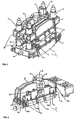
- FIG. 1 shows an axonometric representation of a strand guide segment with an integrated pair of driving rollers
- FIG. 2 shows in a partial section of FIG. 1 the displaceable roller carrier arranged in the inner arc segment frame.
- a cast strand with a still liquid core and a thin strand shell is formed continuously in an oscillating cooled continuous casting mold.
- strand guide with several meters radius of curvature of the casting strand is deflected under constant cooling of substantially vertical direction in the horizontal and directed straight there.
- Some of the strand guide rollers are designed as driver rollers and provided with a motor drive to ensure a controlled conveying speed for the casting strand and at the start of casting for the starter strand.
- Such a continuous casting plant is for example from the DE-A-197 45 056 known.
- the strand guide is composed of individual strand guide segments, as one is shown schematically in Fig. 1 in axonometric representation. It is formed by an outer arch segment frame 1 and an inner arch segment frame 2, which are interconnected by four hydraulically actuable bracing devices 3a, 3b, 3c, 3d arranged in the corner regions of the segment frame, which allow a predetermined positioning of the inner arch segment frame 2 to the outer arch segment frame 1.
- the roller guide 4 mounted in succession strand guide rollers 5 can be adjusted to the degree of strand thickness or casting start on the thickness of the Anfahrstranges.
- Each strand guide roller 5 is formed as a continuous, multi-bearing roller or a plurality of aligned rollers.
- roller carriers 4 are firmly attached to the inner arch 2 or outer arch segment frame 1. However, the roller carriers 4 may also be formed only by the bearing housings 6, which are attached directly to the respective segment frame.
- FIG. 2 shows in a partial section of FIG. 1 a roller carrier 7 which is arranged in the inner-arc segmental frame 2 and carries bearings 8 which receive a multi-bearing strand guide roller 5a, which is connected to a drive 9a in a rotatable manner.
- a similar driven strand guide roller 5b is arranged opposite in the outer arch segment frame 1 and in Fig. 1 by the drive 9b, which is opposite to the drive 9a, indicated.
- the driven strand guide roller 5 b is supported in stationary roller carriers 4 in the same way as the adjacent strand guide rollers 5 fastened in the outer arch segment frame 1.
- the provided for the opposite driven strand guide roller 5a displaceable roller carrier 7 is connected on the one hand via a pivot joint 11 with a controllable pressure medium cylinder 10 and on the other hand via a pivot joint 12 on the inner arc segment frame 2 supported.
- the two pivot joints 11, 12 define a connecting line 13, which corresponds to the line of action of the force application on the cast strand and coincides in Fig. 2 with the central axis of the pressure medium cylinder 10.
- this connection line 13 intersects the central axis 14 of the driven strand guide roller 5a in the middle of its longitudinal extent. This ensures a uniform pressure distribution on the cast strand along the contact line of strand guide roll and cast strand.
- Guides 15a, 16a are fastened on both sides to the displaceable roller carrier 7 in parallel with the connecting lines 13, which interact with corresponding counter-guides 15b, 16b on the inner arc segment frame 2.
- the guides 15a are arranged on the broad sides of the roller carrier 7, approximately at a distance of half a strand guide roller 5a of its side edges.
- the guides 16a bear against the end faces of the roller carrier.
- the guides 15a and counter-guides 15b stabilize the roller carrier 7 in the casting direction G, the guides 16a and counter-guides 16b in the transverse direction thereto.
- the driven Strand guide rollers 5a, 5b, the pressure medium cylinder 10 and the associated guides 15a, 16a formed strand guide element can be arranged without the adjacent stationary strand guide rollers 5 as narrow self-contained strand guide element in the strand guide a continuous casting.
- the outer arc segment frame 1 and the inner arc segment frame 2 are thereby reduced to a guide element frame 17 for the displaceable roller carrier 7 with pressure medium cylinder 10 and the associated guides 15a, 15b, 16a, 16b.
Abstract
Description
Die Erfindung betrifft ein Strangführungselement in einer Brammen- oder Dünnbrammenstranggießanlage gemäß dem Oberbegriff des Anspruchs 1.The invention relates to a strand guiding element in a slab or thin slab caster according to the preamble of claim 1.
In einer Stranggießanlage sind im Bereich der Strangführung zwischen Kokille und dem horizontal angeordneten Auslaufrollgang in Abständen voneinander an den Gießstrang und bei Gießbeginn an den Anfahrstrang anstellbare und antreibbare Strangführungsrollen angeordnet. Durch die von diesen Strangführungsrollen aufgebrachten Anpresskräfte wird der kontrollierte Transport des Gießstranges bzw. des Anfahrstranges durch die Stranggießanlage mit einer vorbestimmten Fördergeschwindigkeit sichergestellt.In a continuous casting in the strand guide between mold and the horizontally arranged outfeed roller table at intervals from each other to the casting strand and at casting start to the Anfahrstrang engageable and drivable strand guide rollers are arranged. By the contact forces applied by these strand guide rollers, the controlled transport of the cast strand or the Anfahrstranges is ensured by the continuous casting at a predetermined conveying speed.
Bei Knüppelstranggießanlagen zum Gießen von Strängen mit nur geringer Querschnittsfläche bis etwa 200mm x 200mm ist es bekannt, einige Treibwalzengerüste in der Strangführung im Abstand voneinander anzuordnen, bei denen die anstellbare und antreibbare Strangführungsrolle des zusammenwirkenden Rollenpaares an einem Schwenkarm gelagert ist, der einerseits mit einer Anstelleinrichtung zum Anpressen der Strangführungsrolle an den Strang gekoppelt und andererseits im Treibwalzengerüstrahmen schwenkbar abgestützt ist (
Ein Treibrollengerüst, welches für Brammen- und Dünnbrammenstranggießanlagen geeignet ist, ist aus der
Für die Anwendung in Brammenstranggießanlagen sind aus der
Aufgabe der Erfindung ist es daher diese Nachteile zu vermeiden und ein Strangführungselement der eingangs genannten Art vorzuschlagen, welches mit konstruktiv geringem Aufwand die symmetrische Aufbringung eines Anpressdruckes auf den Gießstrang ermöglicht und das Fluchten zusammenwirkender Strangführungsrollen sicher gewährleistet. Weiters wird eine Reduktion der Investitions- und Betriebskosten angestrebt.The object of the invention is therefore to avoid these disadvantages and to propose a strand guide element of the type mentioned above, which enables the symmetrical application of a contact pressure on the cast strand with constructively little effort and safely ensures the alignment of co-operating strand guide rolls. Furthermore, a reduction of investment and operating costs is sought.
Die gestellte Aufgabe wird erfindungsgemäß dadurch gelöst, dass Führungen am verlagerbaren Rollenträger mit Gegenführungen am Führungselementrahmen in Eingriff sind und die Verbindungslinie der beiden Schwenkgelenke der Verstelleinrichtung, die der Wirkungslinie der Kraftaufbringung entspricht, normal auf der Mittenachse der verlagerbaren Strangführungsrolle steht.The stated object is achieved according to the invention in that guides on the displaceable roller carrier are engaged with counter guides on the guide element frame and the connecting line of the two pivot joints of the adjusting device, which corresponds to the line of action of the force application, is normal to the center axis of the displaceable strand guide roller.
Um die symmetrische Verteilung des Anpressdruckes entlang der Berührungslinie von Gießstrang und Strangfühungsrolle zu gewährleisten, ist die Verstelleinrichtung mit Schwenkgelenken am Rollenträger und am Führungselementrahmen befestigt. Dieser Effekt wird weiter verbessert, wenn die Verbindungslinie der beiden Schwenkgelenke die Mittelachsen der ein Rollenpaar bildenden Strangführungsrollen schneidet. Die Verstelleinrichtung wird vorzugsweise von einem regelbaren Hydraulikzylinder gebildet.In order to ensure the symmetrical distribution of the contact pressure along the contact line of cast strand and strand guide roller, the adjusting device is attached to the roller carrier and the guide element frame with pivot joints. This effect is further improved if the connecting line of the two pivot joints the Center axes of a pair of rollers forming strand guide rollers cuts. The adjusting device is preferably formed by a controllable hydraulic cylinder.
Eine vorteilhafte Ausgestaltung der Erfindung besteht darin, dass die Führungen am Rollenträger und die Gegenführungen am Führungselementrahmen Berührungsflächen bilden, die parallel zur Verbindungslinie der beiden Schwenkgelenke der Verstelleinrichtung orientiert sind. Damit wird erreicht, dass die Wirkungslinie der Kraftaufbringung gesichert mit der Bewegungsrichtung des Rollenträgers übereinstimmt. Durch eine entsprechende Länge der Führungen und Gegenführungen wird ein Verkanten des Rollenträgers im Führungselementrahmen vermieden.An advantageous embodiment of the invention is that the guides on the roller carrier and the counter guides on the guide element frame form contact surfaces, which are oriented parallel to the connecting line of the two pivot joints of the adjustment. This ensures that the line of action of the force application is consistent with the direction of movement of the roller carrier. By a corresponding length of the guides and counter guides tilting of the roller carrier in the guide element frame is avoided.
Die Erfindung ist nachfolgend anhand eines nicht einschränkenden Ausführungsbeispieles näher erläutert, wobei Fig. 1 eine axonometrische Darstellung eines Strangführungssegmentes mit einem integrierten Treibrollenpaar zeigt und Fig. 2 in einem Teilschnitt der Fig. 1 den im Innenbogensegmentrahmen angeordneten verlagerbaren Rollenträger.The invention is explained in more detail below with reference to a non-limiting exemplary embodiment, wherein FIG. 1 shows an axonometric representation of a strand guide segment with an integrated pair of driving rollers and FIG. 2 shows in a partial section of FIG. 1 the displaceable roller carrier arranged in the inner arc segment frame.
In einer Stranggießanlage zur Herstellung von Strängen im Brammenformat wird in einer oszillierenden gekühlten Stranggießkokille kontinuierlich ein Gießstrang mit noch flüssigem Kern und einer dünnen Strangschale gebildet. In einer der Stranggießkokille in Gießrichtung nachgeordneten Strangführung mit mehreren Metern Krümmungsradius wird der Gießstrang unter ständiger Kühlung von im wesentlichen vertikalen Richtung in die Horizontale umgelenkt und dort gerade gerichtet. Eine Vielzahl von Strangführungsrollen, die in zwei Reihen angeordnet sind, bilden einen Transportkanal für den Gießstrang, in dem er gestützt und geführt wird. Einige der Strangführungsrollen sind als Treiberrollen ausgebildet und mit einem motorischen Antrieb versehen, um eine kontrollierte Fördergeschwindigkeit für den Gießstrang und bei Gießbeginn für den Anfahrstrang zu gewährleisten. Eine derartige Stranggießanlage ist beispielsweise aus der
Die Strangführung ist aus einzelnen Strangführungssegmenten zusammengesetzt, wie eines in Fig. 1 in axonometrischer Darstellung schematisch dargestellt ist. Es ist von je einem Außenbogensegmentrahmen 1 und einem lnnenbogensegmentrahmen 2 gebildet, welche durch vier in den Eckbereichen der Segmentrahmen angeordnete, hydraulisch betätigbare Verspanneinrichtungen 3a, 3b, 3c, 3d miteinander verbunden sind, die eine vorgegebene Positionierung des Innenbogensegmentrahmen 2 zum Außenbogensegmentrahmen 1 zulassen. Damit können die in hintereinander angeordneten Rollenträger 4 gelagerten Strangführungsrollen 5 auf das Maß der Strangdicke oder bei Gießbeginn auf die Dicke des Anfahrstranges eingestellt werden. Jede Strangführungsrolle 5 ist als durchgehende, mehrfach gelagerte Rolle oder von mehreren fluchtenden Rollen gebildet. Einander gegenüberliegende Strangführungsrollen 5 bilden ein zusammenwirkendes Rollenpaar. Die Rollenträger 4 sind fest am Innenbogen- 2 bzw. Außenbogensegmentrahmen 1 befestigt. Die Rollenträger 4 können jedoch auch nur von den Lagergehäusen 6 gebildet sein, die direkt am jeweiligen Segmentrahmen befestigt sind.The strand guide is composed of individual strand guide segments, as one is shown schematically in Fig. 1 in axonometric representation. It is formed by an outer arch segment frame 1 and an inner arch segment frame 2, which are interconnected by four hydraulically
Fig. 2 zeigt in einem Teilschnitt der Fig. 1 einen im lnnenbogensegmentrahmen 2 angeordneten Rollenträger 7, der Lagerstellen 8 trägt, die eine mehrfach gelagerte, mit einem Antrieb 9a verbundene Strangführungsrolle 5a drehbeweglich aufnehmen. Eine gleichartige angetriebene Strangführungsrolle 5b ist im Außenbogensegmentrahmen 1 gegenüberliegend angeordnet und in Fig. 1 durch den Antrieb 9b, der dem Antrieb 9a gegenüberliegt, angedeutet. Die angetriebene Strangführungsrolle 5b ist gleichermaßen wie die benachbarten im Außenbogensegmentrahmen 1 befestigten Strangführungsrollen 5 in stationären Rollenträgern 4 abgestützt. Der für die gegenüberliegende angetriebene Strangführungsrolle 5a vorgesehene verlagerbare Rollenträger 7 ist einerseits über ein Schwenkgelenk 11 mit einem ansteuerbaren Druckmittelzylinder 10 verbunden und andererseits über ein Schwenkgelenk 12 am lnnenbogensegmentrahmen 2 abgestützt. Die beiden Schwenkgelenke 11, 12 bestimmen eine Verbindungslinie 13, die der Wirkungslinie der Kraftaufbringung auf dem Gießstrang entspricht und in Fig. 2 mit der Mittelachse des Druckmittelzylinders 10 zusammenfällt. Damit schneidet diese Verbindungslinie 13 die Mittelachse 14 der angetriebenen Strangführungsrolle 5a in der Mitte ihrer Längserstreckung. Damit ist eine gleichmäßige Druckverteilung auf den Gießstrang entlang der Berührungslinie von Strangführungsrolle und Gießstrang gewährleistet.FIG. 2 shows in a partial section of FIG. 1 a roller carrier 7 which is arranged in the inner-arc segmental frame 2 and carries bearings 8 which receive a multi-bearing strand guide roller 5a, which is connected to a
Parallel zu den Verbindungslinien 13 sind Führungen 15a, 16a beidseitig am verlagerbaren Rollenträger 7 befestigt, die mit entsprechenden Gegenführungen 15b, 16b am lnnenbogensegmentrahmen 2 zusammenwirken. Die Führungen 15a sind an den Breitseiten des Rollenträgers 7, etwa im Abstand einer halben Strangführungsrolle 5a von seinen Seitenrändern angeordnet. Die Führungen 16a liegen an den Stirnseiten des Rollenträgers an. Die Führungen 15a und Gegenführungen 15b stabilisieren den Rollenträger 7 in Gießrichtung G, die Führungen 16a und Gegenführungen 16b in Querrichtung dazu.
Das anhand der Fig. 1 und 2 dargestellte, in ein Strangführungssegment integrierte, von einem verlagerbaren Rollenträger 7, einem stationären Rollenträger 4, den angetriebenen Strangführungsrollen 5a, 5b, dem Druckmittelzylinder 10 und den zugeordneten Führungen 15a, 16a gebildete Strangführungselement kann auch ohne die benachbarten stationären Strangführungsrollen 5 als schmal gebautes eigenständiges Strangführungselement in der Strangführung einer Stranggießanlage angeordnet sein. Der Außenbogensegmentrahmen 1 und der Innenbogensegmentrahmen 2 reduzieren sich dadurch auf einen Führungselementrahmen 17 für den verlagerbaren Rollenträger 7 mit Druckmittelzylinder 10 und den zugeordneten Führungen 15a, 15b, 16a, 16b.The illustrated with reference to FIGS. 1 and 2, integrated in a strand guide segment, by a movable roller carrier 7, a stationary roller carrier 4, the driven Strand guide rollers 5a, 5b, the
Claims (4)
- Strand guide element in a slab or thin-slab continuous casting plant, consisting of at least two strand guide rolls (5a, 5b) which form a cooperating pair of rolls and which are mounted in roll carriers (4, 7) lying up to one another, at least one roll carrier (7) being arranged displaceably in relation to the opposite roll carrier (4) in a common guide-element frame (17), at least one roll (5a, 5b) of the pair of rolls being coupled to a rotary drive (9a, 9b), only one adjustment device (10) being arranged, which engages centrically on the displaceable roll carrier (7) and on the guide-element frame (17), and the adjustment device (10) being fastened by means of pivot joints (11, 12) to the displaceable roll carrier (7) and to the guide-element frame (17), characterized in that guides (15a, 16a) on the displaceable roll carrier (7) are in engagement with counterguides (15b, 16b) on the guide-element frame (17), and the connecting line (13) of the two pivot joints (11, 12) of the adjustment device (10), the said connecting line corresponding to the line of action of the application of force, standing normally to the mid-axis (14) of the displaceable strand guide roller (5a).
- Strand guide element according to Claim 1, characterized in that the connecting line (13) of the two pivot joints (11, 12) intersects the mid-axes (14) of the strand guide rolls (5a, 5b) forming a pair of rolls.
- Strand guide element according to one of the preceding claims, characterized in that the adjustment device (10) is formed by a hydraulic cylinder.
- Strand guide element according to one of the preceding claims, characterized in that the guides (15a, 16a) on the roll carrier (7) and the counterguides (15b, 16b) on the guide-element frame (17) form contact surfaces which are oriented parallel to the connecting line (13) of the two pivot joints (11, 12) of the adjustment device (10).
Priority Applications (1)
| Application Number | Priority Date | Filing Date | Title |
|---|---|---|---|
| EP06020534A EP1752238B1 (en) | 2000-06-02 | 2001-04-20 | Strand guide segment |
Applications Claiming Priority (3)
| Application Number | Priority Date | Filing Date | Title |
|---|---|---|---|
| AT0041500U AT3953U3 (en) | 2000-06-02 | 2000-06-02 | STRING GUIDING ELEMENT AND STRING GUIDING SEGMENT WITH INTEGRATED STRING GUIDING ELEMENT |
| AT4152000U | 2000-06-02 | ||
| PCT/EP2001/004510 WO2001094051A1 (en) | 2000-06-02 | 2001-04-20 | Strand guide element, and strand guide segment with a strand guide element integrated therein |
Related Child Applications (1)
| Application Number | Title | Priority Date | Filing Date |
|---|---|---|---|
| EP06020534A Division EP1752238B1 (en) | 2000-06-02 | 2001-04-20 | Strand guide segment |
Publications (2)
| Publication Number | Publication Date |
|---|---|
| EP1289689A1 EP1289689A1 (en) | 2003-03-12 |
| EP1289689B1 true EP1289689B1 (en) | 2007-07-18 |
Family
ID=3489998
Family Applications (2)
| Application Number | Title | Priority Date | Filing Date |
|---|---|---|---|
| EP01933864A Expired - Lifetime EP1289689B1 (en) | 2000-06-02 | 2001-04-20 | Strand guide element |
| EP06020534A Expired - Lifetime EP1752238B1 (en) | 2000-06-02 | 2001-04-20 | Strand guide segment |
Family Applications After (1)
| Application Number | Title | Priority Date | Filing Date |
|---|---|---|---|
| EP06020534A Expired - Lifetime EP1752238B1 (en) | 2000-06-02 | 2001-04-20 | Strand guide segment |
Country Status (6)
| Country | Link |
|---|---|
| EP (2) | EP1289689B1 (en) |
| CN (1) | CN1184034C (en) |
| AT (1) | AT3953U3 (en) |
| BR (1) | BR0111391B1 (en) |
| DE (2) | DE50115522D1 (en) |
| WO (1) | WO2001094051A1 (en) |
Cited By (1)
| Publication number | Priority date | Publication date | Assignee | Title |
|---|---|---|---|---|
| DE102014202995A1 (en) | 2013-09-16 | 2015-03-19 | Sms Siemag Ag | Frame for a strand guide segment |
Families Citing this family (17)
| Publication number | Priority date | Publication date | Assignee | Title |
|---|---|---|---|---|
| SE526914C2 (en) * | 2003-12-02 | 2005-11-15 | Skf Ab | A segmented roller for an extruder |
| DE102004048618A1 (en) * | 2004-10-06 | 2006-04-13 | Sms Demag Ag | Method and roller segment for determining the core solidification and / or the sump tip in the continuous casting of metals, in particular of steel materials |
| DE102005028703A1 (en) * | 2005-06-20 | 2006-12-28 | Siemens Ag | Regulating and or controlling method e.g. for adjusting segment in continuous casting installation, involves having lower frame and upper frame positioned in relation to each other by adjusting elements |
| KR20100099133A (en) * | 2008-01-14 | 2010-09-10 | 에스엠에스 콘캐스트 에이지 | Continuous casting system particularly for long steel products, and a method for continuous casting |
| AT506549B1 (en) * | 2008-03-28 | 2011-06-15 | Siemens Vai Metals Tech Gmbh | TRAIN TOUR SEGMENT |
| AT506846B1 (en) * | 2008-05-23 | 2011-08-15 | Siemens Vai Metals Tech Gmbh | TRAIN TOUR SEGMENT |
| DE102008025548A1 (en) * | 2008-05-28 | 2009-12-03 | Sms Siemag Aktiengesellschaft | Strand guide, in particular for a continuous steel slab caster |
| AT509352B1 (en) * | 2010-02-05 | 2014-06-15 | Siemens Vai Metals Tech Gmbh | ROAD GUIDE SEGMENT IN CASSETTE CONSTRUCTION WITH SINGLE ROLLING |
| DE102011003194A1 (en) * | 2010-05-19 | 2011-11-24 | Sms Siemag Ag | roller device |
| AT510178A2 (en) | 2010-07-27 | 2012-02-15 | Siemens Vai Metals Tech Gmbh | DEVICE FOR LIMITING THE SLICING OF AN ADJUSTABLE WHEEL SUPPORT |
| AT512214B1 (en) | 2011-12-05 | 2015-04-15 | Siemens Vai Metals Tech Gmbh | PROCESS ENGINEERING MEASURES IN A CONTINUOUS CASTING MACHINE AT THE CASTING STAGE, AT THE CASTING END AND AT THE PRODUCTION OF A TRANSITION PIECE |
| DE102014206685A1 (en) | 2013-12-23 | 2015-06-25 | Sms Siemag Ag | Adjustment device in a device for Kühlmittelbedüsung in a metallurgical plant |
| CN104057049B (en) * | 2014-07-09 | 2016-06-15 | 北京科技大学 | The continuous casting machine fan-shaped segment of the big pressure of continuous casting billet solidifying end and big reduction method thereof |
| AT516412B1 (en) * | 2014-10-28 | 2017-07-15 | Primetals Technologies Austria GmbH | Strand guide roller unit for a continuous casting machine |
| CN108015244B (en) * | 2017-12-05 | 2023-11-14 | 马鞍山钢铁股份有限公司 | Sector section structure of continuous casting machine |
| AT521416B1 (en) * | 2018-07-02 | 2024-01-15 | Primetals Technologies Austria GmbH | Strand guide segment with individually movable strand guide rollers |
| CN113369449A (en) * | 2021-05-19 | 2021-09-10 | 宣化钢铁集团有限责任公司 | Dual-drive arc-shaped transmission device |
Family Cites Families (7)
| Publication number | Priority date | Publication date | Assignee | Title |
|---|---|---|---|---|
| CH515760A (en) * | 1969-05-13 | 1971-11-30 | Concast Ag | Device for guiding a strand in the secondary cooling zone during continuous casting in arch systems |
| AT335650B (en) | 1975-05-13 | 1977-03-25 | Voest Ag | FOR CONTINUOUS CASTING PLANTS |
| AT338984B (en) | 1975-11-12 | 1977-09-26 | Voest Ag | SUPPORT AND GUIDE FRAMEWORK, IN PARTICULAR SUPPORT AND GUIDE BOWS FOR CAST BRANDS |
| DE2923108C2 (en) * | 1978-01-04 | 1986-05-15 | Voest-Alpine Ag, Linz | Driving roll stand for a continuous caster |
| DE3029990C2 (en) * | 1980-08-08 | 1982-08-05 | Mannesmann AG, 4000 Düsseldorf | Continuous casting roll stand for multi-strand casting plants for the continuous casting of metal, in particular steel |
| AT373801B (en) * | 1982-07-22 | 1984-02-27 | Voest Alpine Ag | CHOCOLATE OF A CONTINUOUS CASTING SYSTEM |
| DE19745056A1 (en) * | 1997-10-11 | 1999-04-15 | Schloemann Siemag Ag | Process and plant for producing slabs in a continuous caster |
-
2000
- 2000-06-02 AT AT0041500U patent/AT3953U3/en not_active IP Right Cessation
-
2001
- 2001-04-20 BR BRPI0111391-7A patent/BR0111391B1/en not_active IP Right Cessation
- 2001-04-20 EP EP01933864A patent/EP1289689B1/en not_active Expired - Lifetime
- 2001-04-20 DE DE50115522T patent/DE50115522D1/en not_active Expired - Lifetime
- 2001-04-20 CN CNB018104983A patent/CN1184034C/en not_active Expired - Fee Related
- 2001-04-20 EP EP06020534A patent/EP1752238B1/en not_active Expired - Lifetime
- 2001-04-20 WO PCT/EP2001/004510 patent/WO2001094051A1/en active IP Right Grant
- 2001-04-20 DE DE50112740T patent/DE50112740D1/en not_active Expired - Lifetime
Non-Patent Citations (1)
| Title |
|---|
| None * |
Cited By (1)
| Publication number | Priority date | Publication date | Assignee | Title |
|---|---|---|---|---|
| DE102014202995A1 (en) | 2013-09-16 | 2015-03-19 | Sms Siemag Ag | Frame for a strand guide segment |
Also Published As
| Publication number | Publication date |
|---|---|
| CN1184034C (en) | 2005-01-12 |
| BR0111391A (en) | 2003-06-10 |
| DE50115522D1 (en) | 2010-07-29 |
| AT3953U3 (en) | 2001-04-25 |
| BR0111391B1 (en) | 2009-01-13 |
| EP1752238A2 (en) | 2007-02-14 |
| EP1752238A3 (en) | 2008-08-13 |
| EP1752238B1 (en) | 2010-06-16 |
| DE50112740D1 (en) | 2007-08-30 |
| WO2001094051A1 (en) | 2001-12-13 |
| CN1431942A (en) | 2003-07-23 |
| AT3953U2 (en) | 2000-11-27 |
| EP1289689A1 (en) | 2003-03-12 |
Similar Documents
| Publication | Publication Date | Title |
|---|---|---|
| EP1289689B1 (en) | Strand guide element | |
| EP2257397B1 (en) | Strand guide segment | |
| DE2501956C2 (en) | Device for supporting, guiding, bending or straightening and deforming a wide cast strand | |
| AT506824B1 (en) | MORE STRAND CASTING | |
| DE2630391C2 (en) | Continuous casting mold for strips made from a metal, in particular aluminum, alloy | |
| DE3431316C2 (en) | Guide device on the casting belts of a double-belt continuous casting mold | |
| DE2439359B2 (en) | Strand guide frame in a continuous casting plant | |
| DE3034444A1 (en) | RIGHT DRIVER IN A STEEL CONTINUOUS CASTING SYSTEM | |
| DE2702894B2 (en) | Driving roller frame for a multiple strand caster | |
| DE1758398B2 (en) | Device for transporting and / or straightening metal, especially steel strands in multiple strand casting systems | |
| DE2721856B2 (en) | Strand guides for a multi-strand billet or bloom line with more than two strands for continuous casting of steel | |
| EP0184025A2 (en) | Guide device for the casting strips of a double strip continuous casting mould | |
| EP1425119B1 (en) | Rolling stock guiding device for a horizontal two-high rolling stand | |
| DE1452749A1 (en) | Support means for straightening rolls | |
| DE4442567A1 (en) | Simplified driver unit for rolled strip | |
| DE1941186A1 (en) | Exchangers for roller straighteners for - straightening and smoothing carriers, angle | |
| EP0058869B1 (en) | Guiding support stand in the driving and/or straightening range of a continuous casting plant | |
| AT316038B (en) | Device for guiding an oscillating continuous casting mold in a continuous caster with a curved strand axis | |
| DE2451272C3 (en) | Rod guide frame for a continuous caster | |
| DE2112998A1 (en) | Rolling mill | |
| DE2304845C3 (en) | Device for guiding an oscillating continuous casting mold in a continuous casting plant with a curved strand axis | |
| DE2451272B2 (en) | ROLLER GUIDE FRAMEWORK FOR A CONTINUOUS CASTING PLANT | |
| DE2000136C3 (en) | Arrangement for the running control of an endless casting belt in a continuous casting machine with a casting wheel | |
| WO2023169747A1 (en) | Arch segment of a strand-guiding device | |
| DE19964017A1 (en) | Strand guiding segment used for continuous casting comprises a frame whose frame parts with strand guiding rollers are arranged to guide a casting strand between them using hydraulic devices |
Legal Events
| Date | Code | Title | Description |
|---|---|---|---|
| PUAI | Public reference made under article 153(3) epc to a published international application that has entered the european phase |
Free format text: ORIGINAL CODE: 0009012 |
|
| 17P | Request for examination filed |
Effective date: 20021119 |
|
| AK | Designated contracting states |
Designated state(s): AT BE CH CY DE DK ES FI FR GB GR IE IT LI LU MC NL PT SE TR Kind code of ref document: A1 Designated state(s): AT BE CH CY DE DK ES FI FR GB GR IE IT LI LU MC NL PT SE TR |
|
| RBV | Designated contracting states (corrected) |
Designated state(s): AT BE DE IT |
|
| RBV | Designated contracting states (corrected) |
Designated state(s): DE IT |
|
| GRAP | Despatch of communication of intention to grant a patent |
Free format text: ORIGINAL CODE: EPIDOSNIGR1 |
|
| RTI1 | Title (correction) |
Free format text: STRAND GUIDE ELEMENT |
|
| GRAS | Grant fee paid |
Free format text: ORIGINAL CODE: EPIDOSNIGR3 |
|
| GRAA | (expected) grant |
Free format text: ORIGINAL CODE: 0009210 |
|
| RAP1 | Party data changed (applicant data changed or rights of an application transferred) |
Owner name: SIEMENS VAI METALS TECHNOLOGIES GMBH & CO |
|
| AK | Designated contracting states |
Kind code of ref document: B1 Designated state(s): DE IT |
|
| REF | Corresponds to: |
Ref document number: 50112740 Country of ref document: DE Date of ref document: 20070830 Kind code of ref document: P |
|
| PLBE | No opposition filed within time limit |
Free format text: ORIGINAL CODE: 0009261 |
|
| STAA | Information on the status of an ep patent application or granted ep patent |
Free format text: STATUS: NO OPPOSITION FILED WITHIN TIME LIMIT |
|
| 26N | No opposition filed |
Effective date: 20080421 |
|
| REG | Reference to a national code |
Ref country code: DE Ref legal event code: R082 Ref document number: 50112740 Country of ref document: DE Representative=s name: KINNSTAETTER, KLAUS, DIPL.-PHYS.UNIV., DE |
|
| REG | Reference to a national code |
Ref country code: DE Ref legal event code: R082 Ref document number: 50112740 Country of ref document: DE Representative=s name: KINNSTAETTER, KLAUS, DIPL.-PHYS.UNIV., DE Ref country code: DE Ref legal event code: R081 Ref document number: 50112740 Country of ref document: DE Owner name: PRIMETALS TECHNOLOGIES AUSTRIA GMBH, AT Free format text: FORMER OWNER: SIEMENS VAI METALS TECHNOLOGIES GMBH & CO. KG, LINZ, AT |
|
| PGFP | Annual fee paid to national office [announced via postgrant information from national office to epo] |
Ref country code: DE Payment date: 20170419 Year of fee payment: 17 |
|
| PGFP | Annual fee paid to national office [announced via postgrant information from national office to epo] |
Ref country code: IT Payment date: 20170424 Year of fee payment: 17 |
|
| REG | Reference to a national code |
Ref country code: DE Ref legal event code: R119 Ref document number: 50112740 Country of ref document: DE |
|
| PG25 | Lapsed in a contracting state [announced via postgrant information from national office to epo] |
Ref country code: DE Free format text: LAPSE BECAUSE OF NON-PAYMENT OF DUE FEES Effective date: 20181101 |
|
| PG25 | Lapsed in a contracting state [announced via postgrant information from national office to epo] |
Ref country code: IT Free format text: LAPSE BECAUSE OF NON-PAYMENT OF DUE FEES Effective date: 20180420 |