DE102014202995A1 - Frame for a strand guide segment - Google Patents
Frame for a strand guide segment Download PDFInfo
- Publication number
- DE102014202995A1 DE102014202995A1 DE201410202995 DE102014202995A DE102014202995A1 DE 102014202995 A1 DE102014202995 A1 DE 102014202995A1 DE 201410202995 DE201410202995 DE 201410202995 DE 102014202995 A DE102014202995 A DE 102014202995A DE 102014202995 A1 DE102014202995 A1 DE 102014202995A1
- Authority
- DE
- Germany
- Prior art keywords
- strand
- roller
- strand guide
- frame
- guide
- Prior art date
- Legal status (The legal status is an assumption and is not a legal conclusion. Google has not performed a legal analysis and makes no representation as to the accuracy of the status listed.)
- Pending
Links
Images


Classifications
-
- B—PERFORMING OPERATIONS; TRANSPORTING
- B22—CASTING; POWDER METALLURGY
- B22D—CASTING OF METALS; CASTING OF OTHER SUBSTANCES BY THE SAME PROCESSES OR DEVICES
- B22D11/00—Continuous casting of metals, i.e. casting in indefinite lengths
- B22D11/12—Accessories for subsequent treating or working cast stock in situ
- B22D11/1206—Accessories for subsequent treating or working cast stock in situ for plastic shaping of strands
-
- B—PERFORMING OPERATIONS; TRANSPORTING
- B22—CASTING; POWDER METALLURGY
- B22D—CASTING OF METALS; CASTING OF OTHER SUBSTANCES BY THE SAME PROCESSES OR DEVICES
- B22D11/00—Continuous casting of metals, i.e. casting in indefinite lengths
- B22D11/12—Accessories for subsequent treating or working cast stock in situ
- B22D11/128—Accessories for subsequent treating or working cast stock in situ for removing
-
- B—PERFORMING OPERATIONS; TRANSPORTING
- B22—CASTING; POWDER METALLURGY
- B22D—CASTING OF METALS; CASTING OF OTHER SUBSTANCES BY THE SAME PROCESSES OR DEVICES
- B22D11/00—Continuous casting of metals, i.e. casting in indefinite lengths
- B22D11/16—Controlling or regulating processes or operations
- B22D11/20—Controlling or regulating processes or operations for removing cast stock
- B22D11/208—Controlling or regulating processes or operations for removing cast stock for aligning the guide rolls
Abstract
Die Erfindung betrifft einen Rahmen (5, 6), insbesondere Oberrahmen (5) oder Unterrahmen (6), für ein Strangführungssegment (3) einer Strangführungseinrichtung (1) einer Stranggießanlage (2), aufweisend – wenigstens eine quer zur Strangführungsrichtung (7) angeordnete Rollentraverse (8), an der wenigstens eine Strangführungsrolle (9) drehbeweglich anordbar ist, – zwei parallel zur Strangführungsrichtung (7) und zueinander sowie beabstandet voneinander angeordnete Seitenelemente (10), an denen die Rollentraverse (9) in Strangdickenrichtung (11) bewegbar gelagert ist, – wenigstens eine die Seitenelemente (10) fest miteinander verbindende, quer zur Strangführungsrichtung (7) angeordnete Quertraverse (12), und – wenigstens zwei ansteuerbare Aktoren (13), mittels denen die Rollentraverse (9) in Strangdickenrichtung (11) bewegbar ist, – wobei ein Aktor (13) an einem Endbereich der Rollentraverse (9) und an einem der Seitenelemente (10) angreift, und wobei der andere Aktor (13) an dem anderen Endbereich der Rollentraverse (9) und an dem anderen Seitenelement (10) angreift.The invention relates to a frame (5, 6), in particular upper frame (5) or lower frame (6), for a strand guide segment (3) of a strand guiding device (1) of a continuous casting plant (2), comprising - at least one arranged transversely to the strand guiding direction (7) Roller crossmember (8) on which at least one strand guide roller (9) is rotatably arranged, - two side elements (10) parallel to the strand guide direction (7) and spaced from each other, on which the roller crossmember (9) in the strand thickness direction (11) movably mounted is, - at least one of the side elements (10) fixedly interconnecting, transverse to the strand guide direction (7) arranged crosspiece (12), and - at least two controllable actuators (13), by means of which the roller crossmember (9) in the strand thickness direction (11) is movable In which an actuator (13) acts on an end region of the roller crossbeam (9) and on one of the side elements (10), and wherein the other actuator (13) 13) engages the other end portion of the roller beam (9) and the other side member (10).
Description
Die Erfindung betrifft einen Rahmen, insbesondere Oberrahmen oder Unterrahmen, für ein Strangführungssegment einer Strangführungseinrichtung einer Stranggießanlage.The invention relates to a frame, in particular upper frame or subframe, for a strand guide segment of a strand guiding device of a continuous casting plant.
Des Weiteren betrifft die Erfindung ein Strangführungssegment für eine Strangführungseinrichtung einer Stranggießanlage, aufweisend einen Oberrahmen und einen Unterrahmen.Furthermore, the invention relates to a strand guide segment for a strand guiding device of a continuous casting plant, comprising a top frame and a bottom frame.
Ferner betrifft die Erfindung eine Strangführungseinrichtung für eine Stranggießanlage, aufweisend mehrere in Reihe angeordnete Strangführungssegmente.Furthermore, the invention relates to a strand guide device for a continuous casting, comprising a plurality of strand guide segments arranged in series.
Aus der Veröffentlichung
Die Veröffentlichung
Die europäische Patentschrift
Die Veröffentlichung
Die europäische Patentschrift
Aufgabe der Erfindung ist es, den mit einem Betrieb einer segmentierten Strangführungseinrichtung einer Stranggießanlage verbundenen Wartungsaufwand bzw. damit verbundene Wartungszeiten und Wartungskosten zu verringern.The object of the invention is to reduce the maintenance associated with an operation of a segmented strand guiding device of a continuous casting plant or related maintenance times and maintenance costs.
Diese Aufgabe wird durch einen Rahmen mit den Merkmalen gemäß Anspruch 1, ein Strangführungssegment mit den Merkmalen gemäß Anspruch 8 sowie eine Strangführungseinrichtung mit den Merkmalen gemäß Anspruch 11 gelöst. Vorteilhafte Ausgestaltungen sind in den Unteransprüchen wiedergegeben, welche jeweils für sich genommen oder in verschiedener Kombination miteinander einen Aspekt der Erfindung darstellen können.This object is achieved by a frame having the features according to claim 1, a strand guide segment having the features according to
Mit Patentanspruch 1 wird ein Rahmen, insbesondere Oberrahmen oder Unterrahmen, für ein Strangführungssegment einer Strangführungseinrichtung einer Stranggießanlage vorgeschlagen, aufweisend
- – wenigstens eine quer zur Strangführungsrichtung angeordnete Rollentraverse, an der wenigstens eine Strangführungsrolle drehbeweglich anordbar ist,
- – zwei parallel zur Strangführungsrichtung und zueinander sowie beabstandet voneinander angeordnete Seitenelemente, an denen die Rollentraverse in Strangdickenrichtung bewegbar gelagert ist,
- – wenigstens eine die Seitenelemente fest miteinander verbindende, quer zur Strangführungsrichtung angeordnete Quertraverse, und
- – wenigstens zwei ansteuerbare Aktoren, mittels denen die Rollentraverse in Strangdickenrichtung bewegbar ist,
- – wobei ein Aktor an einem Endbereich der Rollentraverse und an einem der Seitenelemente angreift, und wobei der andere Aktor an dem anderen Endbereich der Rollentraverse und an dem anderen Seitenelement angreift.
- At least one roller cross member arranged transversely to the strand guiding direction, on which at least one strand guiding roller can be arranged in a rotationally movable manner,
- - Two parallel to the strand guide direction and each other and spaced from each other arranged side elements on which the roller cross member is movably mounted in the strand thickness direction,
- - At least one side elements firmly interconnecting, transverse to the strand guide direction arranged cross-beam, and
- At least two controllable actuators, by means of which the roller traverse is movable in the strand thickness direction,
- Wherein an actuator engages an end portion of the roller beam and one of the side members, and wherein the other actuator engages the other end portion of the roller beam and the other side member.
Gemäß der Erfindung ist die in Strangdickenrichtung bewegbar an den Seitenelementen gelagerte Rollentraverse zur Realisierung einer Einzelrollenanstellung über Aktoren mit den starr über wenigstens eine Quertraverse miteinander verbundenen Seitenelementen verbunden. Es ist kein Querhaupt oberhalb der Rollentraverse vorhanden und wie herkömmlich erforderlich, wie es beispielsweise gemäß der oben genannten Veröffentlichung
Der Rahmen kann auch zwei oder mehrere entsprechende quer zur Strangführungsrichtung angeordnete bewegbare Rollentraversen aufweisen. An jeder bewegbaren Rollentraverse können auch zwei oder mehrere zueinander fluchtende Strangführungsrollen drehbeweglich angeordnet sein.The frame may also have two or more corresponding transversely arranged to the strand guide direction movable roller traverses. At each movable roller traverse two or more mutually aligned strand guide rollers can be arranged rotatably.
Der Rahmen kann auch zwei oder mehrere die Seitenelemente fest miteinander verbindende, quer zur Strangführungsrichtung angeordnete Quertraversen aufweisen.The frame may also have two or more side members firmly interconnecting, arranged transversely to the strand guide direction cross members.
Jeder bewegbaren Rollentraverse sind vorzugsweise zwei ansteuerbare Aktoren zugeordnet, mittels denen die jeweilige Rollentraverse in Strangdickenrichtung bewegbar ist.Each movable roller traverse are preferably associated with two controllable actuators, by means of which the respective roller crossbar is movable in the strand thickness direction.
Mittels eines Rahmens können gemäß der Erfindung insbesondere Brammen, wie beispielsweise Stahlbrammen, geführt und bearbeitet werden. By means of a frame in particular slabs, such as steel slabs, can be guided and processed according to the invention.
Der zu führende Strang kann hierbei kontinuierlich oder segmentiert ausgebildet sein. Insbesondere kann eine Bearbeitung von Brammen in Form einer sogenannten Softreduction-Bearbeitung erfolgen, wobei eine rollenpositionsgenaue Einwirkung auf die geführten Brammen möglich ist. Ferner kann der Rahmen bei einem Strangführungssegment eingesetzt werden, welches eine Cyberlink-Funktion aufweist, wie sie beispielsweise in dem
Gemäß einer vorteilhaften Ausgestaltung weist der Rahmen zwei oder mehrere quer zur Strangführungsrichtung angeordnete, in Strangdickenrichtung bewegbar an den Seitenelementen gelagerte, mittels jeweils zwei ansteuerbaren Aktoren in Strangdickenrichtung bewegbare Rollentraversen auf, wobei die Rollentraversen in Strangführungsrichtung im Wechsel mit der wenigstens einen Quertraverse angeordnet sind. Dies stellt eine konstruktiv hochwertige und robuste Ausgestaltung des Rahmens dar. Es kann vorgesehen sein, dass ein- und austrittsseitig jeweils eine Quertraverse angeordnet ist, zwischen denen die Rollentraversen angeordnet sind.According to an advantageous embodiment, the frame has two or more transversely to the strand guide direction arranged in the strand thickness direction movably mounted on the side elements movable by means of two controllable actuators in strand thickness direction roller traverses, wherein the roller traverses are arranged in strand guide direction in alternation with the at least one cross-beam. This represents a structurally high-quality and robust design of the frame. It can be provided that on each side and on the exit side a respective cross-member is arranged, between which the roller traverses are arranged.
Nach einer weiteren vorteilhaften Ausgestaltung ist wenigstens ein Aktor als Arbeitszylinder, insbesondere Plungerzylinder, ausgebildet, dessen Kolbenstange an der jeweiligen Rollentraverse angreift. Vorzugsweise sind alle Aktoren als, insbesondere hydraulische, Arbeitszylinder ausgebildet. Dies stellt eine konstruktiv einfache, kostengünstige und gleichzeitig robuste Ausgestaltung der Aktoren dar.According to a further advantageous embodiment, at least one actuator is designed as a working cylinder, in particular plunger cylinder, whose piston rod acts on the respective roller beam. Preferably, all actuators are designed as, in particular hydraulic, working cylinder. This represents a structurally simple, cost-effective and at the same time robust design of the actuators.
Vorteilhafterweise liegt der Zylinderhub des Arbeitszylinders in einem Bereich von 2 mm bis 50 mm. Ein Zylinderhub in einem Bereich von 2 mm bis 50 mm ist insbesondere bei der Verwendung des Rahmens zur Ausbildung eines Cyberlink-Strangführungssegmentes von Vorteil. Die Bemessung des jeweiligen Zylinderhubs kann unter Berücksichtigung einer angestrebten Softreduction-Rate erfolgen.Advantageously, the cylinder stroke of the working cylinder is in a range of 2 mm to 50 mm. A cylinder stroke in a range of 2mm to 50mm is particularly advantageous when using the frame to form a cyberlink strand guide segment. The dimensioning of the respective cylinder stroke can take place taking into account a desired soft reduction rate.
Vorzugsweise ist der Zylinderhub in Richtung eines geführten Strangs durch wenigstens einen einstellbaren mechanischen Endanschlag begrenzt. Dies schafft eine einfache Begrenzung der Bewegbarkeit eines Kolbens eines Arbeitszylinders bzw. einer bewegbaren Rollentraverse. Die Einstellbarkeit des mechanischen Endanschlags macht eine Anpassung des Rahmens an die jeweiligen Gegebenheiten und Anforderungen möglich.Preferably, the cylinder stroke is limited in the direction of a guided strand by at least one adjustable mechanical end stop. This provides a simple limitation on the mobility of a piston of a working cylinder or a movable roller traverse. The adjustability of the mechanical end stop makes it possible to adapt the frame to the respective circumstances and requirements.
Nach einer weiteren vorteilhaften Ausführungsform ist mittels an einer Rollentraverse angreifenden Arbeitszylindern ein Arbeitsdruck aufbringbar, welcher bis zu 20% über einem auf die Rollentraverse einwirkenden ferrostatischen Druck oder über einem Gesamtdruck aus dem ferrostatischen Druck und einem durch eine Softreduction-Reaktion bedingten Druck liegt. Dies macht eine optimale Bearbeitung eines geführten Strangs möglich.According to a further advantageous embodiment, a working pressure can be applied by means acting on a roller beam working cylinders, which is up to 20% above a force acting on the roller traverse ferrostatic pressure or a total pressure from the ferrostatic pressure and a conditional by a soft reduction reaction pressure. This makes optimal processing of a guided strand possible.
Bevorzugt weist der Rahmen wenigstens einen mit dem Arbeitszylinder zusammenwirkenden Weggeber auf. Bei einer Softreduction-Bearbeitung eines Strangs nimmt die Tragfähigkeit des Strangs hinter der Durcherstarrung üblicherweise in erheblichem Maße zu. Daher kann es dazu kommen, dass bewegbare Rollentraversen bzw. an diesen angeordnete Strangführungsrollen dem Strang ausweichen und sich von ihren mechanischen Auflagen auf dem Rahmen entfernen. Mittels des Weggebers kann ein solches Ausweichen der Strangführungsrollen erfasst und für eine Steuerung von nachgeschalteten Strangführungssegmenten verwendet werden, beispielsweise um deren eingangsseitigen Öffnungsmaße zu bestimmen. The frame preferably has at least one displacement sensor cooperating with the working cylinder. In a soft reduction processing of a strand, the load-bearing capacity of the strand behind the solidification usually increases to a considerable extent. Therefore, it may happen that movable roller trays or arranged on this strand guide rollers dodge the strand and move away from their mechanical constraints on the frame. By means of the displacement sensor, such a deflection of the strand guide rollers can be detected and used for a control of downstream strand guide segments, for example, to determine their input-side opening dimensions.
Mit Patentanspruch 8 wird ein Strangführungssegment für eine Strangführungseinrichtung einer Stranggießanlage vorgeschlagen, aufweisend einen Oberrahmen und einen Unterrahmen, dadurch gekennzeichnet, dass der Oberrahmen und/oder der Unterrahmen gemäß einer der vorgenannten Ausgestaltungen oder einer beliebigen Kombination derselben ausgebildet ist. Mit diesem Strangführungssegment sind die oben mit Bezug auf den Rahmen genannten Vorteile entsprechend verbunden.With
Der Ober- und/oder Unterrahmen kann für ein Strangführungssegment, in dem erwartungsgemäß die Sumpfspitze des geführten Strangs liegt, mittels an dem Oberrahmen und an dem Unterrahmen angreifenden Langhubzylindern, welche beispielsweise einen Zylinderhub in einem Bereich von 100 mm bis 500 mm aufweisen, auf eine Neigung zwischen der eingangsseitigen und der ausgangsseitigen Strangführungsrolle eingestellt werden, welche dem natürlichen Schrumpf der erstarrten Strangschale in diesem Strangabschnitt zuzüglich der angestrebten Softreduction-Rate entspricht. Alle anderen Strangführungssegmente einer Strangführungseinrichtung, also die vor und hinter der Sumpfspitze angeordneten Strangführungssegmente, können, soweit sie über eine Online-Gießdickenverstellung verfügen, auf den üblichen Maschinentaper eingestellt werden, der sich in der Regel nach dem natürlichen Schrumpf der erstarrten Strangschale bzw. des durcherstarrten Strangs richtet.The upper and / or subframe may for a strand guide segment, in which the expected expected the bottom tip of the guided strand, acting on the upper frame and on the lower frame Langhubzylindern having, for example, a cylinder stroke in a range of 100 mm to 500 mm, on a Inclination between the input side and the output side strand guide roller can be adjusted, which corresponds to the natural shrinkage of the solidified strand shell in this strand section plus the desired Softreduction rate. All other strand guide segments of a strand guiding device, that is, the strand guide segments arranged in front of and behind the sump tip, can be adjusted to the usual machine taper, which usually has the natural shrinkage of the solidified strand shell or of the solidified through, if they have an online Gießdickenverstellung Strangs aimed.
Eine vorhandene Strangführungseinrichtung kann auf einfache Art und Weise mit entsprechenden Strangführungssegmenten nachgerüstet werden.An existing strand guide device can be retrofitted in a simple manner with appropriate strand guide segments.
Nach einer vorteilhaften Ausgestaltung weist das Strangführungssegment zwei parallel zur Strangführungsrichtung und zueinander sowie beabstandet voneinander angeordnete Seitenrahmen auf, über die der Oberrahmen beweglich mit dem Unterrahmen verbunden ist. Der Oberrahmen und/oder der Unterrahmen sind bewegbar mit den Seitenrahmen verbunden.According to an advantageous embodiment, the strand guide segment has two parallel to the strand guide direction and each other and spaced from each other arranged side frame over which the upper frame is movably connected to the subframe. The upper frame and / or the lower frame are movably connected to the side frames.
Gemäß einer weiteren vorteilhaften Ausgestaltung ist wenigstens eine Rollentraverse über, vorzugsweise elastisch ausgebildete, Führungselemente derart in Strangdickenrichtung bewegbar an den Seitenelementen gelagert, dass die Rollentraverse in einem vorgebbaren Ausmaß quer zu der Strangdickenrichtung bewegbar an den Seitenelementen gelagert ist. Hierdurch kann trotz der massiven Seitenrahmen des Strangführungssegmentes eine Cyberlink-Funktion, also eine Selbstzentrierung von bewegbaren Rollentraversen und Strangführungsrollen, realisiert werden. Die Führungselemente sind vorzugsweise reibungsarm oder reibungsfrei ausgeführt.According to a further advantageous embodiment, at least one roller traverse over, preferably elastically formed, guide elements so movably mounted in the strand thickness direction on the side elements, that the roller cross member is mounted transversely to the strand thickness direction movable on the side members to a predetermined extent. In this way, despite the massive side frames of the strand guide segment Cyberlink function, ie a self-centering of movable roller trays and strand guide rollers can be realized. The guide elements are preferably designed friction or friction.
Mit Patentanspruch 11 wird eine Strangführungseinrichtung für eine Stranggießanlage vorgeschlagen, aufweisend mehrere in Reihe angeordnete Strangführungssegmente, dadurch gekennzeichnet, dass wenigstens ein Strangführungssegment gemäß einer der vorgenannten Ausgestaltungen oder einer beliebigen Kombination derselben ausgebildet ist. Mit dieser Strangführungseinrichtung sind die oben mit Bezug auf den Rahmen bzw. das Strangführungssegment genannten Vorteile entsprechend verbunden.With
Vorteilhafterweise weist die Strangführungseinrichtung eine elektronische Automatisierungseinrichtung auf, wobei zwischen den einzelnen Strangführungssegmenten und der Automatisierungseinrichtung elektrische Steckverbindungen vorhanden sind, welche derart ausgebildet sind, dass mittels der Automatisierungseinrichtung erfassbar ist, welche Strangführungssegmente an welcher Position in der Strangführungseinrichtung angeordnet sind. Hierdurch kann eine Verwechslung zwischen unterschiedlichen Strangführungssegmenttypen ausgeschlossen werden.Advantageously, the strand guiding device has an electronic automation device, electrical connections being present between the individual strand guiding segments and the automation device, which are designed in such a way that by means of the automation device it can be detected which strand guiding segments are arranged at which position in the strand guiding device. As a result, a confusion between different strand guide segment types can be excluded.
Ferner wird vorgeschlagen, dass die Automatisierungseinrichtung eingerichtet ist, eine Strangführung unter Berücksichtigung der in der jeweiligen Strangführungseinrichtung angeordneten Strangführungssegmente individuell durchzuführen. Dies macht eine fallgerechte Automatisierung der Strangführungseinrichtung möglich.It is also proposed that the automation device is set up to carry out a strand guide individually, taking into account the strand guide segments arranged in the respective strand guiding device. This makes a case-based automation of the strand guiding device possible.
Im Folgenden wird die Erfindung unter Bezugnahme auf die anliegenden Figuren anhand von bevorzugten Ausführungsbeispielen exemplarisch erläutert, wobei die nachfolgend dargestellten Merkmale sowohl jeweils für sich genommen als auch in verschiedener Kombination miteinander einen Aspekt der Erfindung darstellen können. Es zeigenIn the following, the invention will be explained by way of example with reference to the attached figures with reference to preferred exemplary embodiments, wherein the features illustrated below may represent an aspect of the invention both individually and in various combinations with one another. Show it
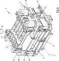
Des Weiteren umfasst die Strangführungseinrichtung
Der Oberrahmen
Die Aktoren
Die Rollentraversen
BezugszeichenlisteLIST OF REFERENCE NUMBERS
- 11
- Strangführungseinrichtung Strand guide
- 22
- Stranggießanlage continuous casting plant
- 33
- Strangführungssegment Strand guide segment
- 44
- Automatisierungseinrichtung automation equipment
- 55
- Oberrahmen top frame
- 66
- Unterrahmen subframe
- 77
- Strangführungsrichtung Strand guiding direction
- 88th
- Rollentraverse Traverse role
- 99
- Strangführungsrolle Strand guide roller
- 1010
- Seitenelement page element
- 1111
- Strangdickenrichtung Strand thickness direction
- 1212
- Quertraverse crossbeam
- 1313
- Aktor actuator
- 1414
- Führungselement guide element
- 1515
- Doppelpfeil double arrow
- 1616
- Kopplungseinheit coupling unit
- 1717
- Führungseinheit Guide unit
- 1818
- Führungselement guide element
- 1919
- Führungselement guide element
- 2020
- Führungskörper guide body
- 2121
- Führungseinrichtung guide means
- 2222
- Seitenrahmen side frame
- 2323
- Nut groove
- 2424
- Körper body
- 2525
- Führungsnut guide
- 2626
- Führungseinheit Guide unit
- 2727
- Gleitkörper sliding
- 2828
- Führungsnut guide
ZITATE ENTHALTEN IN DER BESCHREIBUNG QUOTES INCLUDE IN THE DESCRIPTION
Diese Liste der vom Anmelder aufgeführten Dokumente wurde automatisiert erzeugt und ist ausschließlich zur besseren Information des Lesers aufgenommen. Die Liste ist nicht Bestandteil der deutschen Patent- bzw. Gebrauchsmusteranmeldung. Das DPMA übernimmt keinerlei Haftung für etwaige Fehler oder Auslassungen.This list of the documents listed by the applicant has been generated automatically and is included solely for the better information of the reader. The list is not part of the German patent or utility model application. The DPMA assumes no liability for any errors or omissions.
Zitierte PatentliteraturCited patent literature
- WO 2011/095383 A1 [0004, 0012] WO 2011/095383 A1 [0004, 0012]
- WO 2009/144001 A1 [0005] WO 2009/144001 A1 [0005]
- EP 1289689 B1 [0006] EP 1289689 B1 [0006]
- WO 2006/037555 A1 [0007] WO 2006/037555 A1 [0007]
- EP 0963263 B1 [0008] EP 0963263 B1 [0008]
Zitierte Nicht-PatentliteraturCited non-patent literature
- Artikel „Innovation in der Stranggießtechnik: Verbesserung von Qualität und Wirtschaftlichkeit durch CyberLink-Technologie“ in der Fachzeitschrift „Stahl und Eisen“, 2002 [0017] Article "Innovation in Continuous Casting: Improving Quality and Efficiency through CyberLink Technology" in the journal "Steel and Iron", 2002 [0017]
Claims (13)
Priority Applications (1)
| Application Number | Priority Date | Filing Date | Title |
|---|---|---|---|
| DE201410202995 DE102014202995A1 (en) | 2013-09-16 | 2014-02-19 | Frame for a strand guide segment |
Applications Claiming Priority (3)
| Application Number | Priority Date | Filing Date | Title |
|---|---|---|---|
| DE102013218461 | 2013-09-16 | ||
| DE102013218461.1 | 2013-09-16 | ||
| DE201410202995 DE102014202995A1 (en) | 2013-09-16 | 2014-02-19 | Frame for a strand guide segment |
Publications (1)
| Publication Number | Publication Date |
|---|---|
| DE102014202995A1 true DE102014202995A1 (en) | 2015-03-19 |
Family
ID=52580143
Family Applications (1)
| Application Number | Title | Priority Date | Filing Date |
|---|---|---|---|
| DE201410202995 Pending DE102014202995A1 (en) | 2013-09-16 | 2014-02-19 | Frame for a strand guide segment |
Country Status (1)
| Country | Link |
|---|---|
| DE (1) | DE102014202995A1 (en) |
Cited By (3)
| Publication number | Priority date | Publication date | Assignee | Title |
|---|---|---|---|---|
| CN108788041A (en) * | 2018-07-03 | 2018-11-13 | 东北大学 | Fan-shaped section roll array structure and application method are used under a kind of weight of continuous casting and solidifying end |
| CN110666121A (en) * | 2018-07-02 | 2020-01-10 | 首要金属科技奥地利有限责任公司 | Strand guide segment with individually movable strand guide rollers |
| EP3613519A1 (en) * | 2018-08-24 | 2020-02-26 | SMS Group GmbH | Strand guiding element of a strand casting installation |
Citations (5)
| Publication number | Priority date | Publication date | Assignee | Title |
|---|---|---|---|---|
| EP0963263B1 (en) | 1997-01-27 | 2001-10-31 | SMS Demag AG | Strand guide, specially for a slab continuous casting installation |
| WO2006037555A1 (en) | 2004-10-06 | 2006-04-13 | Sms Demag Ag | Method and roll segment for determining core solidification and/or the liquid crater tip in the continuous casting of metals, particularly steel materials |
| EP1289689B1 (en) | 2000-06-02 | 2007-07-18 | Siemens VAI Metals Technologies GmbH & Co | Strand guide element |
| WO2009144001A1 (en) | 2008-05-28 | 2009-12-03 | Sms Siemag Ag | Strand guide, in particular for a continuous casting plant for steel slabs |
| WO2011095383A1 (en) | 2010-02-05 | 2011-08-11 | Siemens Vai Metals Technologies Gmbh | Rod guide segment in cassette design having single roll engagement |
-
2014
- 2014-02-19 DE DE201410202995 patent/DE102014202995A1/en active Pending
Patent Citations (5)
| Publication number | Priority date | Publication date | Assignee | Title |
|---|---|---|---|---|
| EP0963263B1 (en) | 1997-01-27 | 2001-10-31 | SMS Demag AG | Strand guide, specially for a slab continuous casting installation |
| EP1289689B1 (en) | 2000-06-02 | 2007-07-18 | Siemens VAI Metals Technologies GmbH & Co | Strand guide element |
| WO2006037555A1 (en) | 2004-10-06 | 2006-04-13 | Sms Demag Ag | Method and roll segment for determining core solidification and/or the liquid crater tip in the continuous casting of metals, particularly steel materials |
| WO2009144001A1 (en) | 2008-05-28 | 2009-12-03 | Sms Siemag Ag | Strand guide, in particular for a continuous casting plant for steel slabs |
| WO2011095383A1 (en) | 2010-02-05 | 2011-08-11 | Siemens Vai Metals Technologies Gmbh | Rod guide segment in cassette design having single roll engagement |
Non-Patent Citations (1)
| Title |
|---|
| Artikel "Innovation in der Stranggießtechnik: Verbesserung von Qualität und Wirtschaftlichkeit durch CyberLink-Technologie" in der Fachzeitschrift "Stahl und Eisen", 2002 |
Cited By (5)
| Publication number | Priority date | Publication date | Assignee | Title |
|---|---|---|---|---|
| CN110666121A (en) * | 2018-07-02 | 2020-01-10 | 首要金属科技奥地利有限责任公司 | Strand guide segment with individually movable strand guide rollers |
| AT521416A1 (en) * | 2018-07-02 | 2020-01-15 | Primetals Technologies Austria GmbH | Strand guide segment with individually displaceable strand guide rollers |
| AT521416B1 (en) * | 2018-07-02 | 2024-01-15 | Primetals Technologies Austria GmbH | Strand guide segment with individually movable strand guide rollers |
| CN108788041A (en) * | 2018-07-03 | 2018-11-13 | 东北大学 | Fan-shaped section roll array structure and application method are used under a kind of weight of continuous casting and solidifying end |
| EP3613519A1 (en) * | 2018-08-24 | 2020-02-26 | SMS Group GmbH | Strand guiding element of a strand casting installation |
Similar Documents
| Publication | Publication Date | Title |
|---|---|---|
| EP2307152B1 (en) | Rolling device | |
| EP2342026B1 (en) | Rolling apparatus | |
| DE102014202995A1 (en) | Frame for a strand guide segment | |
| AT506836B1 (en) | CONTINUOUS CASTING SYSTEM FOR CASTING A METAL STRUCTURE WITH BUTTON OR SURFACE CROSS SECTION | |
| EP1075943B1 (en) | Printing device | |
| DE3331055C2 (en) | Roll stand with axially movable work rolls | |
| WO2009100813A1 (en) | Strand guide, in particular for a continuous steel slab casting installation | |
| AT504413B1 (en) | Closing unit of an injection molding machine | |
| EP0857522B1 (en) | Rolling mill | |
| EP0602492B1 (en) | Cluster mill | |
| EP1530508A2 (en) | Extruding and pipe press | |
| DE10218779B4 (en) | Storage of the two rollers of a roller mill | |
| DE10116988B4 (en) | rolling mill | |
| AT507111B1 (en) | PRESS | |
| AT521416B1 (en) | Strand guide segment with individually movable strand guide rollers | |
| WO2011035908A1 (en) | Modular guide device | |
| DE102020206297A1 (en) | Interstand guidance on a vertical roll stand of a rolling train as well as a method for guiding the rolling stock using the interstand guidance | |
| EP3370890B1 (en) | Device for adjusting an edging roll of an edging stand | |
| DE102008015008B4 (en) | Method for operating a strand guiding device | |
| DE102016209247B3 (en) | BEARING CASE SUPPORT FOR A TWO-ROLLED ROLLER PRESS | |
| EP3706933B1 (en) | Strand guide segment and continuous casting plant | |
| EP0592918B1 (en) | Conveyor device with a strand of links | |
| DE202012012284U1 (en) | Strand guide for a continuous casting plant | |
| WO2004105981A2 (en) | Casting ladle slide-gate | |
| DE2754405A1 (en) | STRAND GUIDE FOR A STEEL STRAND CASTING PLANT |
Legal Events
| Date | Code | Title | Description |
|---|---|---|---|
| R081 | Change of applicant/patentee |
Owner name: SMS GROUP GMBH, DE Free format text: FORMER OWNER: SMS SIEMAG AG, 40237 DUESSELDORF, DE |
|
| R082 | Change of representative |
Representative=s name: HEMMERICH & KOLLEGEN, DE |
|
| R012 | Request for examination validly filed |