EP1288448A1 - Elektromagnetischer Aktor zur Betätigung eines Brennkraftmaschinen-Hubventils - Google Patents
Elektromagnetischer Aktor zur Betätigung eines Brennkraftmaschinen-Hubventils Download PDFInfo
- Publication number
- EP1288448A1 EP1288448A1 EP02015277A EP02015277A EP1288448A1 EP 1288448 A1 EP1288448 A1 EP 1288448A1 EP 02015277 A EP02015277 A EP 02015277A EP 02015277 A EP02015277 A EP 02015277A EP 1288448 A1 EP1288448 A1 EP 1288448A1
- Authority
- EP
- European Patent Office
- Prior art keywords
- armature
- electromagnetic
- combustion engine
- internal combustion
- electromagnetic actuator
- Prior art date
- Legal status (The legal status is an assumption and is not a legal conclusion. Google has not performed a legal analysis and makes no representation as to the accuracy of the status listed.)
- Granted
Links
- 238000002485 combustion reaction Methods 0.000 title claims abstract description 6
- 230000000694 effects Effects 0.000 description 2
- 239000012530 fluid Substances 0.000 description 1
- 238000000034 method Methods 0.000 description 1
Images

Classifications
-
- F—MECHANICAL ENGINEERING; LIGHTING; HEATING; WEAPONS; BLASTING
- F01—MACHINES OR ENGINES IN GENERAL; ENGINE PLANTS IN GENERAL; STEAM ENGINES
- F01L—CYCLICALLY OPERATING VALVES FOR MACHINES OR ENGINES
- F01L9/00—Valve-gear or valve arrangements actuated non-mechanically
- F01L9/20—Valve-gear or valve arrangements actuated non-mechanically by electric means
Definitions
- the invention relates to an electromagnetic actuator for actuating an internal combustion engine lift valve according to that mentioned in the preamble of claim 1 Characteristics.
- the invention is based on DE 199 38 988 A1.
- an electromagnetic one Actuator for actuating an internal combustion engine lift valve with an intermediate two magnetic coils each oscillating against the force of a return spring moved and described acting on the stem of the lift valve anchor.
- This anchor is elastically deformable and thus acts as a return spring spring element supporting their function.
- the essentially disc-shaped Anchor has a smaller one in the direction of movement in its edge area measured thickness than in its central area.
- the object of the present invention is the mechanical life of the armature to improve.
- the design of the armature according to the invention reduces the generation of a torque which occurs when the armature is in the smallest inclined position when the armature is thicker in the direction of movement in the outer edge region than in the inner region.
- the undesired torque corresponding to the product of the contact force of the armature with the distance of the contact point from the armature rod axis, which accelerates the armature and bends the armature rod, becomes significantly smaller. A significantly longer mechanical lifespan is therefore to be expected for the anchor and anchor rod.
- the invention is based on two preferred exemplary embodiments, which in the form of six sub-figures combined into two figures, in a lot are shown in a highly simplified form, explained in more detail.
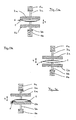
- Figures 1a to 1c show a first embodiment in which a disc-shaped Armature is formed thinner in its radial edge area in the direction of movement is as its center area, while two electromagnetic coils are heading towards of the anchor are just designed.
- Figures 2a to 2c show a second embodiment in which two electromagnetic coils convex in the direction of a disk-shaped anchor are, while the anchor is designed plane-parallel.
- Anchor designated by the reference number 1.
- Anchor 1 is from an upper anchor rod 3a and a lower anchor rod 3b, the free lower end (not shown) on a to be operated and also in the direction of arrow 4 acts to move the lifting valve of a reciprocating internal combustion engine, held.
- an upper return spring 5a which compresses is when the armature 1 is in its upper end position (on the upper electromagnetic coil 2a attached)
- a lower return spring 5b which compresses is when the armature 1 is in its lower rest position (on the lower electromagnetic coil 2b adjacent).
- the two anchor rods 3a, 3b penetrate the each associated magnet coil 2a or 2b in front of or behind the plane of the drawing.
- the upper end position of the armature is shown in FIGS. 1a and 2a, while in FIGS. 1c and 2c the lower rest position of the armature 1 is shown.
- 1b and 2b is the Armature 1 in motion and is currently between the electromagnetic coils 2a, 2b.
- the armature 1 acts like an elastically deformable leaf spring, so that it thereby Return springs 5a, 5b can support their function.
- the flight phase 1b and 2b is the leaf spring formed by the anchor 1 according to the invention relaxed.
- the upper return spring 5a With the armature 1 approaching (for example) the upper one Electromagnetic coil 2a, the upper return spring 5a is compressed. Then come the armature 1 (for example) against the upper electromagnetic coil 2a, As shown in Figs. 1a and 2a, the anchor 1 sets first with his Center area on the electromagnetic coil 2a, 2b.
Landscapes
- Engineering & Computer Science (AREA)
- Mechanical Engineering (AREA)
- General Engineering & Computer Science (AREA)
- Valve Device For Special Equipments (AREA)
Abstract
Description
Die erfindungsgemäße Ausgestaltung des Ankers verringert die Entstehung eines Drehmoments, welches bei kleinster Schiefstellung des Ankers auftritt, wenn der Anker im äußeren Randbereich in Bewegungsrichtung dicker ist als im Innenbereich. Das unerwünschte Drehmoment, entsprechend dem Produkt aus der Anpresskraft des Ankers mit dem Abstand des Berührpunktes von der Ankerstangenachse, welches den Anker drehbeschleunigt und die Ankerstange biegebelastet, wird deutlich kleiner. Eine deutlich längere mechanische Lebensdauer ist somit für Anker und Ankerstange zu erwarten.
Zusätzlich wird ein Kleben zwischen Anker und Magnetspule beim Lösevorgang, der durch einen Saugeffekt, ähnlich er wie bei zwei planen auf einander liegenden Platten auftritt, hervorgerufen wird wesentlich verringert. Das Umgebungsfluid kann bei der erfindungsgemäßen Ausgestaltung leichter in den sich von außen her kontinuierlich öffnenden Spalt eindringen.
Als weiterer wesentlicher Vorteil ist das verringerte Trägheitsmoment aufgrund der reduzierten Masse des Ankers zu nennen. Der für den Betrieb des elektromagnetischen Aktors benötigte Strombedarf wird somit wesentlich verringert, sowie die akustischen Eigenschaften deutlich verbessert.
Weiter ändert sich die Position des Hubventil-Schaftes in der Bewegungsrichtung nicht, wenn der Anker unterschiedlich stark deformiert wird. Dies bedeutet, dass im Anker gerade so viel Energie gespeichert werden kann, dass der Anker entsprechend den momentanen, durch die Betriebsbedingungen (z. B. Temperatur, Ölviskosität, Kräfte auf Ventil usw.) definierten Widerstand, am gegenüberliegenden Magneten mit sehr geringer Geschwindigkeit auftrifft. Damit kann der notwendige Fangstrom für den Anker auf ein Minimum reduziert werden. Dies bedeutet wiederum erhebliche Stromersparnis, da das Biegen des Ankers bei sehr kleinem Luftspalt, das Fangen jedoch über größere Entfernung erfolgt und die Magnetkraft proportional zum Strom geteilt durch den Luftspalt im Quadrat ist.
Claims (2)
- Elektromagnetischer Aktor zur Betätigung eines Brennkraftmaschinen-Hubventils mit einem zwischen zwei Elektromagnetspulen gegen die Kraft einer Rückstellfeder oszillierend bewegten und dabei auf den Schaft des Hubventils einwirkenden elastisch verformbaren Anker, wobei der Anker derart elastisch verformbar ausgebildet ist, dass er in seiner im wesentlichen vollflächig an den Elektromagnetspulen anliegenden Position aufgrund seiner daraus resultierenden Verformung als ein dann gespanntes Federelement wirkt,
dadurch gekennzeichnet, dass der im wesentlichen scheibenförmige Anker (1) in seinem Randbereich (6) eine kleinere in Bewegungsrichtung gemessene Dicke aufweist als in seinem Mittenbereich. - Elektromagnetischer Aktor nach Anspruch 1,
dadurch gekennzeichnet, dass die Elektromagnetspule (2a, 2b) auf der dem Anker zugewandten Seite derart konvex oder konkav ausgebildet ist, dass der Spalt zwischen Anker (1) und Elektromagnetspule (2a, 2b) im Randbereich (6) größer als im Mittenbereich ist.
Applications Claiming Priority (2)
| Application Number | Priority Date | Filing Date | Title |
|---|---|---|---|
| DE10141945 | 2001-08-28 | ||
| DE10141945A DE10141945A1 (de) | 2001-08-28 | 2001-08-28 | Elektromagnetischer Aktor zur Betätigung eines Brennkraftmaschinen-Hubventils |
Publications (2)
| Publication Number | Publication Date |
|---|---|
| EP1288448A1 true EP1288448A1 (de) | 2003-03-05 |
| EP1288448B1 EP1288448B1 (de) | 2004-03-17 |
Family
ID=7696758
Family Applications (1)
| Application Number | Title | Priority Date | Filing Date |
|---|---|---|---|
| EP02015277A Expired - Lifetime EP1288448B1 (de) | 2001-08-28 | 2002-07-09 | Elektromagnetischer Aktor zur Betätigung eines Brennkraftmaschinen-Hubventils |
Country Status (2)
| Country | Link |
|---|---|
| EP (1) | EP1288448B1 (de) |
| DE (2) | DE10141945A1 (de) |
Cited By (1)
| Publication number | Priority date | Publication date | Assignee | Title |
|---|---|---|---|---|
| WO2017108297A1 (de) * | 2015-12-22 | 2017-06-29 | Robert Bosch Gmbh | Magnetventil für ein kraftstoffeinspritzventil, verfahren zum betreiben des magnetventils und kraftstoffeinspritzventil mit einem solchen magnetventil |
Citations (4)
| Publication number | Priority date | Publication date | Assignee | Title |
|---|---|---|---|---|
| DE19822906A1 (de) * | 1997-07-24 | 1999-01-28 | Fev Motorentech Gmbh & Co Kg | Elektrischer Aktuator mit elastisch verformbarem Anker |
| DE19839180A1 (de) * | 1997-09-19 | 1999-03-25 | Bayerische Motoren Werke Ag | Elektromagnetischer Aktuator zum Antrieb eines Gaswechsel-Hubventils einer Brennkraftmaschine |
| DE19938988A1 (de) * | 1999-08-17 | 2000-11-30 | Bayerische Motoren Werke Ag | Elektromagnetischer Aktuator zur Betätigung eines Brennkraftmaschinen-Hubventiles |
| DE10005590A1 (de) * | 2000-02-09 | 2001-08-16 | Bayerische Motoren Werke Ag | Elektromagnetischer Aktuator zur Hubsteuerung eines Gaswechselventiles einer Brennkraftmaschine |
-
2001
- 2001-08-28 DE DE10141945A patent/DE10141945A1/de not_active Withdrawn
-
2002
- 2002-07-09 EP EP02015277A patent/EP1288448B1/de not_active Expired - Lifetime
- 2002-07-09 DE DE50200298T patent/DE50200298D1/de not_active Expired - Fee Related
Patent Citations (4)
| Publication number | Priority date | Publication date | Assignee | Title |
|---|---|---|---|---|
| DE19822906A1 (de) * | 1997-07-24 | 1999-01-28 | Fev Motorentech Gmbh & Co Kg | Elektrischer Aktuator mit elastisch verformbarem Anker |
| DE19839180A1 (de) * | 1997-09-19 | 1999-03-25 | Bayerische Motoren Werke Ag | Elektromagnetischer Aktuator zum Antrieb eines Gaswechsel-Hubventils einer Brennkraftmaschine |
| DE19938988A1 (de) * | 1999-08-17 | 2000-11-30 | Bayerische Motoren Werke Ag | Elektromagnetischer Aktuator zur Betätigung eines Brennkraftmaschinen-Hubventiles |
| DE10005590A1 (de) * | 2000-02-09 | 2001-08-16 | Bayerische Motoren Werke Ag | Elektromagnetischer Aktuator zur Hubsteuerung eines Gaswechselventiles einer Brennkraftmaschine |
Cited By (1)
| Publication number | Priority date | Publication date | Assignee | Title |
|---|---|---|---|---|
| WO2017108297A1 (de) * | 2015-12-22 | 2017-06-29 | Robert Bosch Gmbh | Magnetventil für ein kraftstoffeinspritzventil, verfahren zum betreiben des magnetventils und kraftstoffeinspritzventil mit einem solchen magnetventil |
Also Published As
| Publication number | Publication date |
|---|---|
| EP1288448B1 (de) | 2004-03-17 |
| DE10141945A1 (de) | 2003-03-20 |
| DE50200298D1 (de) | 2004-04-22 |
Similar Documents
| Publication | Publication Date | Title |
|---|---|---|
| DE69517335T2 (de) | Elektromagnetisch gelenktes ventil mit gelenkter armatur | |
| EP0245614B1 (de) | Vorrichtung zum Betätigen eines Gaswechsel-Tellerventils einer Hubkolben-Brennkraftmaschine | |
| EP0428570A1 (de) | Stelleinrichtung für ein gaswechselventil einer brennkraftmaschine | |
| WO2009050215A2 (de) | Aktiv gesteuertes ventil und verfahren zum betrieb des ventils | |
| EP1417398A1 (de) | Drehaktor-vorrichtung zur hubsteuerung eines gaswechsel-tellerventils im zylinderkopf einer brennkraftmaschine | |
| DE19828945A1 (de) | Vorrichtung zum Aktivieren und Deaktivieren eines Ladungswechselventils einer Brennkraftmaschine | |
| EP0244878A2 (de) | Elektromagnetisch-hydraulischer Ventiltrieb für Verbrennungskraftmaschinen | |
| DE10003928A1 (de) | Elektromagnetischer Aktuator | |
| DE29620741U1 (de) | Schmalbauender elektromagnetischer Aktuator | |
| EP0193640A1 (de) | Sitzventileinrichtung | |
| DE29713167U1 (de) | Elektromagnetischer Aktuator mit elastisch verformbarem Anker | |
| DE19720858A1 (de) | Elektromagnetische Betätigungsvorrichtung | |
| EP1288448B1 (de) | Elektromagnetischer Aktor zur Betätigung eines Brennkraftmaschinen-Hubventils | |
| DE19756201A1 (de) | Elektromagnetisch betätigtes Ventil mit thermischer Kompensation | |
| EP1187972B1 (de) | Elektromagnetischer aktuator und verfahren zur justierung des elektromagnetischen aktuators | |
| DE19646937C2 (de) | Elektromagnetische Betätigungsvorrichtung für ein Brennkraftmaschinen-Hubventil | |
| EP0793004B1 (de) | Elektromagnetische Ventilbetätigung | |
| DE19607019A1 (de) | Vorrichtung zur elektromagnetischen Betätigung eines Gaswechselventiles für Verbrennungsmotoren | |
| DE19725010C1 (de) | Vorrichtung zur Betätigung eines Gaswechselventils mit einem elektromagnetischen Aktuator | |
| DE19922424C2 (de) | Elektromagnetischer Stellantrieb | |
| DE19822907B4 (de) | Elektromagnetischer Aktuator mit gelenkig abgestützter Rückstellfeder | |
| DE10038575B4 (de) | Elektromagnetische Stelleinrichtung | |
| DE69618551T2 (de) | Elektromagnetischer Betätiger mit Kern mit niedrigem Seitenverhältnis | |
| EP4449458A1 (de) | Elektromagnetischer aktuator | |
| DE10248070A1 (de) | Elektromagnetische Ventilbetätigung mit weichem Anschlag an den Ventilsitz |
Legal Events
| Date | Code | Title | Description |
|---|---|---|---|
| PUAI | Public reference made under article 153(3) epc to a published international application that has entered the european phase |
Free format text: ORIGINAL CODE: 0009012 |
|
| AK | Designated contracting states |
Kind code of ref document: A1 Designated state(s): AT BE BG CH CY CZ DE DK EE ES FI FR GB GR IE IT LI LU MC NL PT SE SK TR |
|
| AX | Request for extension of the european patent |
Extension state: AL LT LV MK RO SI |
|
| 17P | Request for examination filed |
Effective date: 20030412 |
|
| 17Q | First examination report despatched |
Effective date: 20030519 |
|
| GRAP | Despatch of communication of intention to grant a patent |
Free format text: ORIGINAL CODE: EPIDOSNIGR1 |
|
| AKX | Designation fees paid |
Designated state(s): DE FR GB IT |
|
| GRAS | Grant fee paid |
Free format text: ORIGINAL CODE: EPIDOSNIGR3 |
|
| GRAA | (expected) grant |
Free format text: ORIGINAL CODE: 0009210 |
|
| AK | Designated contracting states |
Kind code of ref document: B1 Designated state(s): DE FR GB IT |
|
| REG | Reference to a national code |
Ref country code: GB Ref legal event code: FG4D Free format text: NOT ENGLISH |
|
| GBT | Gb: translation of ep patent filed (gb section 77(6)(a)/1977) |
Effective date: 20040317 |
|
| REG | Reference to a national code |
Ref country code: IE Ref legal event code: FG4D Free format text: GERMAN |
|
| REF | Corresponds to: |
Ref document number: 50200298 Country of ref document: DE Date of ref document: 20040422 Kind code of ref document: P |
|
| REG | Reference to a national code |
Ref country code: IE Ref legal event code: FD4D |
|
| ET | Fr: translation filed | ||
| PLBE | No opposition filed within time limit |
Free format text: ORIGINAL CODE: 0009261 |
|
| STAA | Information on the status of an ep patent application or granted ep patent |
Free format text: STATUS: NO OPPOSITION FILED WITHIN TIME LIMIT |
|
| 26N | No opposition filed |
Effective date: 20041220 |
|
| PGFP | Annual fee paid to national office [announced via postgrant information from national office to epo] |
Ref country code: FR Payment date: 20050728 Year of fee payment: 4 |
|
| PGFP | Annual fee paid to national office [announced via postgrant information from national office to epo] |
Ref country code: DE Payment date: 20050909 Year of fee payment: 4 |
|
| PGFP | Annual fee paid to national office [announced via postgrant information from national office to epo] |
Ref country code: GB Payment date: 20060727 Year of fee payment: 5 |
|
| PGFP | Annual fee paid to national office [announced via postgrant information from national office to epo] |
Ref country code: IT Payment date: 20060731 Year of fee payment: 5 |
|
| PG25 | Lapsed in a contracting state [announced via postgrant information from national office to epo] |
Ref country code: DE Free format text: LAPSE BECAUSE OF NON-PAYMENT OF DUE FEES Effective date: 20070201 |
|
| GBPC | Gb: european patent ceased through non-payment of renewal fee |
Effective date: 20070709 |
|
| PG25 | Lapsed in a contracting state [announced via postgrant information from national office to epo] |
Ref country code: GB Free format text: LAPSE BECAUSE OF NON-PAYMENT OF DUE FEES Effective date: 20070709 |
|
| REG | Reference to a national code |
Ref country code: FR Ref legal event code: ST Effective date: 20080331 |
|
| PG25 | Lapsed in a contracting state [announced via postgrant information from national office to epo] |
Ref country code: FR Free format text: LAPSE BECAUSE OF NON-PAYMENT OF DUE FEES Effective date: 20070731 |
|
| PG25 | Lapsed in a contracting state [announced via postgrant information from national office to epo] |
Ref country code: FR Free format text: LAPSE BECAUSE OF NON-PAYMENT OF DUE FEES Effective date: 20060731 |
|
| PG25 | Lapsed in a contracting state [announced via postgrant information from national office to epo] |
Ref country code: IT Free format text: LAPSE BECAUSE OF NON-PAYMENT OF DUE FEES Effective date: 20070709 |