EP1286178A2 - Procédé de détection optique du sol - Google Patents
Procédé de détection optique du sol Download PDFInfo
- Publication number
- EP1286178A2 EP1286178A2 EP02016031A EP02016031A EP1286178A2 EP 1286178 A2 EP1286178 A2 EP 1286178A2 EP 02016031 A EP02016031 A EP 02016031A EP 02016031 A EP02016031 A EP 02016031A EP 1286178 A2 EP1286178 A2 EP 1286178A2
- Authority
- EP
- European Patent Office
- Prior art keywords
- ground
- scanning
- radiation
- characteristic
- scanning plane
- Prior art date
- Legal status (The legal status is an assumption and is not a legal conclusion. Google has not performed a legal analysis and makes no representation as to the accuracy of the status listed.)
- Ceased
Links
Images


Classifications
-
- G—PHYSICS
- G01—MEASURING; TESTING
- G01S—RADIO DIRECTION-FINDING; RADIO NAVIGATION; DETERMINING DISTANCE OR VELOCITY BY USE OF RADIO WAVES; LOCATING OR PRESENCE-DETECTING BY USE OF THE REFLECTION OR RERADIATION OF RADIO WAVES; ANALOGOUS ARRANGEMENTS USING OTHER WAVES
- G01S7/00—Details of systems according to groups G01S13/00, G01S15/00, G01S17/00
- G01S7/48—Details of systems according to groups G01S13/00, G01S15/00, G01S17/00 of systems according to group G01S17/00
- G01S7/4802—Details of systems according to groups G01S13/00, G01S15/00, G01S17/00 of systems according to group G01S17/00 using analysis of echo signal for target characterisation; Target signature; Target cross-section
-
- G—PHYSICS
- G01—MEASURING; TESTING
- G01S—RADIO DIRECTION-FINDING; RADIO NAVIGATION; DETERMINING DISTANCE OR VELOCITY BY USE OF RADIO WAVES; LOCATING OR PRESENCE-DETECTING BY USE OF THE REFLECTION OR RERADIATION OF RADIO WAVES; ANALOGOUS ARRANGEMENTS USING OTHER WAVES
- G01S17/00—Systems using the reflection or reradiation of electromagnetic waves other than radio waves, e.g. lidar systems
- G01S17/88—Lidar systems specially adapted for specific applications
- G01S17/93—Lidar systems specially adapted for specific applications for anti-collision purposes
- G01S17/931—Lidar systems specially adapted for specific applications for anti-collision purposes of land vehicles
-
- G—PHYSICS
- G01—MEASURING; TESTING
- G01S—RADIO DIRECTION-FINDING; RADIO NAVIGATION; DETERMINING DISTANCE OR VELOCITY BY USE OF RADIO WAVES; LOCATING OR PRESENCE-DETECTING BY USE OF THE REFLECTION OR RERADIATION OF RADIO WAVES; ANALOGOUS ARRANGEMENTS USING OTHER WAVES
- G01S7/00—Details of systems according to groups G01S13/00, G01S15/00, G01S17/00
- G01S7/48—Details of systems according to groups G01S13/00, G01S15/00, G01S17/00 of systems according to group G01S17/00
- G01S7/497—Means for monitoring or calibrating
-
- G—PHYSICS
- G06—COMPUTING; CALCULATING OR COUNTING
- G06V—IMAGE OR VIDEO RECOGNITION OR UNDERSTANDING
- G06V20/00—Scenes; Scene-specific elements
- G06V20/50—Context or environment of the image
- G06V20/56—Context or environment of the image exterior to a vehicle by using sensors mounted on the vehicle
- G06V20/588—Recognition of the road, e.g. of lane markings; Recognition of the vehicle driving pattern in relation to the road
-
- G—PHYSICS
- G01—MEASURING; TESTING
- G01S—RADIO DIRECTION-FINDING; RADIO NAVIGATION; DETERMINING DISTANCE OR VELOCITY BY USE OF RADIO WAVES; LOCATING OR PRESENCE-DETECTING BY USE OF THE REFLECTION OR RERADIATION OF RADIO WAVES; ANALOGOUS ARRANGEMENTS USING OTHER WAVES
- G01S17/00—Systems using the reflection or reradiation of electromagnetic waves other than radio waves, e.g. lidar systems
- G01S17/02—Systems using the reflection of electromagnetic waves other than radio waves
- G01S17/06—Systems determining position data of a target
- G01S17/42—Simultaneous measurement of distance and other co-ordinates
-
- G—PHYSICS
- G01—MEASURING; TESTING
- G01S—RADIO DIRECTION-FINDING; RADIO NAVIGATION; DETERMINING DISTANCE OR VELOCITY BY USE OF RADIO WAVES; LOCATING OR PRESENCE-DETECTING BY USE OF THE REFLECTION OR RERADIATION OF RADIO WAVES; ANALOGOUS ARRANGEMENTS USING OTHER WAVES
- G01S17/00—Systems using the reflection or reradiation of electromagnetic waves other than radio waves, e.g. lidar systems
- G01S17/87—Combinations of systems using electromagnetic waves other than radio waves
Definitions
- the invention relates to a method for detecting soil by means of at least a vehicle-mounted opto-electronic detection device.
- Opto-electronic detection devices such as video cameras and laser scanners are used in conjunction with vehicles used to monitor the environment of the vehicle and in the surveillance area to recognize objects located and, where appropriate, to follow. For this it is necessary to recognize the soil as such and of "real" objects, in particular other road users to distinguish, for example, unnecessary braking to avoid that can be accidentally triggered when an example in the horizontal direction "looking" detection device due to a pitching motion of the vehicle temporarily on the roadway is addressed and this mistakenly considered a supposed, in Direction of travel in front of the vehicle befindaji object is detected.
- the object of the invention is to provide a soil detection method of the initially to create said type, with the most reliable way of Floor can be distinguished from other objects.
- the electromagnetic radiation in several Scanned planes emitted wherein at least two scanning planes from each other are different.
- the emission of radiation in at least two different scanning levels basically opens up the advantageous possibility a three-dimensional or quasi-three-dimensional scan, because at any distance within the range of different scanning planes different height levels are sampled.
- Different scanning levels also minimize the time in which the vehicle due to a non-normal operation Instantaneous behavior - eg. B. due to pitching or rolling movements - "blind" is because at least one scanning level still useful Information provides when one or more scan planes z. B. due a bump into the sky.
- At least one characteristic Floor characteristic is specified, which in the evaluation of the radiation reflected radiation is used.
- the radiation reflected in at least one of the scanning planes becomes then examined whether those contained in the reflected radiation Information on the presence of at least one characteristic Indicate soil characteristic. If in the evaluation the presence recognized at least one characteristic soil feature is, then can be connected to a connected evaluation a corresponding Be given signal, whereupon, for example, with the help of a appropriate measures can be taken central control device.
- These measures may consist of the evaluation of the total radiation received from the surveillance area complement and capture the scenery in which the vehicle is currently located on the basis of the ground detection To improve information. It is also possible to be active in the Driving the vehicle or in the operation of individual vehicle equipment intervene.
- the optoelectronic detection device to a laser scanner which is responsible for the emission of radiation in at least one scanning plane is formed and for each within the Scanning plane emitted scanning beam according to the principle of the light transit time measurement a distance value and for this distance value one Angle value related to a given axis supplies.
- the angular range can be selected in principle arbitrary over the sampling and in particular up to 360 °.
- At least an opto-electronic detection device in particular at least a laser scanner used to emit radiation is formed in several different scanning planes.
- a single one Such, for the transmission of several different scanning levels capable Detection device is sufficient for the soil detection method according to the invention in principle.
- this detection device only a single radiation source, in particular in the form of a Laser diode on.
- At least one opto-electronic detection device in particular at least one laser scanner used is, the or for in at least one scanning plane emitted radiation has at least one Strahlungsumlenk issued over which at least one additional scanning plane is generated.
- the radiation deflecting device may be, for example act one or more plane mirrors.
- deflecting devices may be a part of one, also called the main scan plane Scanning plane are directed specifically in certain directions.
- the deflectors can basically any relative orientation between the individual scan planes will be realized.
- the invention proposes that the sampling in several different scanning planes from different directions he follows. This makes it possible, for example, a region of special Interest, especially the ground in the direction of travel in front of the vehicle or side of the vehicle, simultaneously from several directions too "consider”.
- At least two optoelectronic Detecting devices in particular laser scanner used each to emit radiation in a single scan plane are formed and operated so that at least two scanning planes are different from each other.
- Soil feature at least one characteristic shape of bottom lines is given, each of which received in a scanning plane ground reflections be formed.
- Typical floor-line forms for example determined empirically and in a memory of a connected Evaluation unit can be stored, in this case for soil detection used. Lines received during evaluation Soil reflections can be generated as part of an evaluation algorithm They then examine how well they are with one or more match given characteristic bottom line shapes.
- the ground feature Position of at least one having a characteristic shape, from bottom line received floor reflections received in a scan plane is specified relative to the detection device.
- the invention proposes that as a soil feature at least one characteristic ground pattern is given, whose Ground lines received from several different scan planes Floor reflections are formed.
- the object "ground” for example be recognized that two or more under one well-known angles apart scanning planes in different Distances hit the ground, resulting in the evaluation of received reflections leads to a characteristic scan image, the For example, it differs from the one that hitting the Scan planes on a vertical wall or on the ground the rear of a preceding truck would be detected.
- According to another embodiment of the invention is as a soil feature the characteristic temporal behavior of at least one in particular a characteristic shape bottom line in successive Specified scanning.
- At least a characteristic shape having bottom line on the Closed course of the floor In particular, in a straight Ground line closed on a level ground. According to the invention, not only the object "ground” recognized as such, but it can also obtained more information about the detected soil become.
- the invention further proposes, from at least one characteristic Shape having ground line on the angle between the Scanning plane and the ground, especially on the size of slopes and slopes, close. This is done in particular by the fact that the Slope of a characteristic ground line determined during the evaluation is evaluated.
- the invention proposes that at least one characteristic Irregularity or discontinuity within a characteristic Form having ground line on the presence of a Uneven ground is closed.
- the knowledge is exploited, that with appropriate orientation of the respective scanning plane uneven floors such as a curb to an irregularity or jump in a characteristic ground line, which would have a steady course on even ground.
- the Irregularity or discontinuity can be with appropriate orientation the scanning plane in particular have a Z-shaped course.
- the detection of curbs or other limiting the road or the road course reproducing objects by means of The soil detection method according to the invention can advantageously Way as part of an algorithm for detecting the course of the road be used.
- a characteristic shape having ground lines respectively generated by at least one radiation deflecting device.
- At least two scanning planes are generated, which are so different are oriented to the direction of travel, that two different oriented and preferably intersecting floor lines are generated.
- the scanning planes are preferably symmetrical to the direction of travel of the Vehicle oriented.
- the knowledge is used that - at least during normal driving - "real" objects such. B. other road users "not from Fall sky ", but previously by means of at least one scanning plane in such a way be recognized in time that the first received reflections, the can not be assigned to any of the previously recognized "real” objects, at least with some probability as coming from the ground must be considered.
- the invention proposes, as a characteristic of the soil Specify the shape and / or width of such floor reflection pulses, at an angle other than 90 ° between the scanning plane and the ground.
- This variant makes use of the knowledge that the of an inclined surface such as in front of the vehicle in the direction of travel, rising roadway reflected radiation pulses of a different shape and / or have width as such reflection pulses from a perpendicular on the floor standing wall, z. B. the rear of a truck come.
- the invention further proposes that from the characteristic Shape and / or width of the bottom reflection pulses of the angle between the Scanning plane and the ground is determined. This allows, for example calculate the size of slopes and slopes.
- At least an opto-electronic detection device in particular at least a laser scanner, provided with the radiation in the manner of a Fan is sent simultaneously in several scanning levels.
- the targeted directed to the ground at a distance from the detection device is expected from the normal driving ground reflections.
- the orientation of the detection device is automatically changed so that the with the bottom-scanning plane measured distance at least one as normal classified driving is constant.
- the bottom-scanning plane serves as a kind of "support foot” for the detection device having a constant orientation of the remaining scanning planes in particular also ensures if the Vehicle is pitching or rolling or is about to start To climb or descend.
- the use of a targeted to Floor detection plane serving ground detection is particularly suitable for the realization of an automatic or dynamic pitch and Wankwinkelkompensation.
- the Alignment of the detection device by tracking a vehicle device is changed, to which the detection device attached is.
- the detection device can consequently be used for a constant orientation of the relevant vehicle device relative to the ground, regardless of location of the vehicle relative to the ground.
- this Variant of the invention when it comes to the vehicle device is about a vehicle headlight. A basically in everyone any driving situation consistent alignment of the vehicle headlights relative to the ground can in this way by the invention be ensured.
- the invention further proposes for the evaluation of the received Radiation such additional information about the instantaneous behavior the vehicle, in particular during braking or acceleration, Cornering and / or uneven weight distributions, which leads to a deviation from the normal orientation of the Lead vehicle on the ground.
- the invention also relates to the use of one or more optoelectronic detection devices, in particular one or several laser scanners, with which in particular pulsed electromagnetic Radiation emitted in at least two different scanning planes and receive radiation reflected from a surveillance area and is evaluated in conjunction with a vehicle for Ground detection according to a method as set forth above.
- FIGS. 1, 2 and 3 each show an embodiment of a laser scanner 13, which is provided with two plane mirrors 17, which in the vehicle mounted state preferably symmetrically with respect to the direction of travel are arranged.
- the radiation emitted by the scanner 13 is on the one hand via a Angle range of nearly 180 ° directly in a main scanning plane 15 and about the mirror 17 in two more, each having an angular range of about 40 ° covering scanning planes 15 emitted so that a total of three different scanning planes 15 is worked.
- all three scanning planes 15 lie in one common level, whereby the effective sampling frequency is increased because for each revolution of the scanner 13 in the overlapping area of the Scanning levels 15 lying regions are scanned repeatedly.
- a multiple scanning plane emitting scanner 13 is also called a multi-line scanner indicates that an object detected by the scanning planes 15 scanned line by line.
- the two mirrors 17 are slight, z. B. by a few degrees, tilted against each other, creating a total three differently oriented scanning planes 15 are generated.
- the mirrors 17 are oriented such that the over the mirror 17 emitted scanning planes overlap each other and in the vehicle-mounted state and in the normally aligned Close the vehicle in front of the scanner 13 on the ground.
- a multilevel or multi-line scan enables a pitch compensation without mechanical components to be moved thereby allowing at least most of them to be used in practice Nick movements of the vehicle - z. B. due to uneven floors or braking operations - always at least one of the scanning planes 15 in one direction "looks", in for the surveillance of the vehicle environment important objects are detected safely, in the example as shown in FIG. 3, the two transmitted via the mirror 17 scanning planes 15 specifically used for soil detection.
- the ground detection according to the invention by checking the received Radiation on the presence of characteristic soil features
- each arbitrary oriented scanning plane 15 and so that not only for the targeted for ground detection parked scanning planes 15 according to FIG. 3, but also for all scanning planes 15 of FIG. 1 and Fig. 2 are performed.
- FIG. 4 shows a typical scan image measured with a laser scanner 13 was, as shown in Fig. 2, d. H. with a laser scanner, the only relatively slightly tilted mirror 17 has.
- the laser scanners 13 preferably operate at a wavelength of 905 nm (near IR), so that each of the mirrors 17 is an infrared mirror.
- the vehicle on which the laser scanner 13 is mounted moves in the x-direction on a roadway, by means of the two lower ones Scanning levels 15 (see Fig. 2) is detected by the fact that the ground reflections detect characteristic bottom lines 19.
- the means of the lower Scanning plane 15 detected ground line 19 hits the road in a shorter distance from the scanner 13 than the middle scanning plane 15, which consequently increased compared to the edges of the roadway clearly more pronounced while the upper (main) scanning plane 15 not or only out of range of the scanner 13 on the road meets.
- Fig. 4 makes it clear that according to the invention a soil detection not only via the detection of characteristic bottom lines 19 per se, but Moreover, it is possible that the formed by the bottom lines 19 characteristic soil pattern recognized as such in the evaluation becomes.
- FIG. 5 shows a scan image taken with a scanner 13, as shown in Fig. 3.
- the comparatively strong from the Horizontal tilted mirror 17 emitted scanning planes 15 "look" in a relatively short distance of z. B. about 2 m before the on the vehicle attached scanner 13 on the ground.
- the in these scanning planes 15 received reflections form a characteristic soil pattern in the form of two crossed characteristic ground lines 19.
- the slope calculation can be performed by means of the upper (main) scanning plane 15 (see Fig. 3) are checked for plausibility that the actual Distance at which the upper scanning plane 15 hits the road and that shown in the upper part of Fig. 5, transverse to the direction of travel extending bottom line 19 is compared with a predicted value which is obtained from the intersecting floor lines 19.
- FIG. 6 shows a further possibility for determining road inclinations or - falls. This is a scanned image Projection of scan points into the x-z plane, d. H. the y coordinate became ignored.
- ground line 19 may be the size of the road gradient or the roadway gradient are calculated.
- Fig. 7a shows a scan image, which in turn with a laser scanner 13, such as it is shown in Fig. 3, was taken and according to FIG. 5 showing intersecting, characteristic ground lines 19, of the come via the mirror 17 emitted scanning planes 15.
- a laser scanner 13 such as it is shown in Fig. 3
- FIG. 5 showing intersecting, characteristic ground lines 19, of the come via the mirror 17 emitted scanning planes 15.
- With the upper, directly transmitted scanning plane 15 is another, left before Own vehicle 33 "seen” and based on recognized its characteristic form.
- the bottom line rising from left to right 19 has a Z-shaped Jump point 21 on.
- Such irregularities in the characteristic Floor lines 19 are created by scanning uneven floors.
- the ground unevenness is concerned around a curb, resulting in the characteristic irregularity or jump 21.
- the representation in Fig. 6 corresponding Projection can easily determine the height of curb 21 become.
- the invention thus enables not only the Soil detection itself, but also the quantitative determination a soil profile.
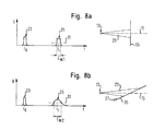
- FIGS. 8a and 8b show another possibility, on the one hand the floor recognize as such and on the other hand more information about the Gain ground.
- FIGS. 8a and 8b shows one at a time t0 from the laser scanner 13 emitted radiation pulse 23, the after Reflection on a surface 35 at a later time t1 as a reflection pulse 25 is received.
- the shape of the reflection pulse 25 and in particular in a predetermined threshold 31 measured width W is due to the expansion of the laser beam 29 from the angle between the scanning plane 15, in FIG which the beam 29 is emitted, and the respective reflective Surface 35 dependent. Since inclined with respect to the scanning plane 15 Reflection surface 35 of FIG. 8b, the front of the expanded beam 29th impinges on the reflection surface 35 at different times, is the Width W2 of the relevant reflection pulse 25 is greater than the width W1 of the perpendicular to the scanning plane 15 extending reflection surface 35 reflected pulse 25 of FIG. 8a.
Applications Claiming Priority (2)
| Application Number | Priority Date | Filing Date | Title |
|---|---|---|---|
| DE10141294.0A DE10141294B4 (de) | 2001-08-23 | 2001-08-23 | Verfahren zur Bodenerkennung |
| DE10141294 | 2001-08-23 |
Publications (2)
| Publication Number | Publication Date |
|---|---|
| EP1286178A2 true EP1286178A2 (fr) | 2003-02-26 |
| EP1286178A3 EP1286178A3 (fr) | 2003-11-05 |
Family
ID=7696331
Family Applications (1)
| Application Number | Title | Priority Date | Filing Date |
|---|---|---|---|
| EP02016031A Ceased EP1286178A3 (fr) | 2001-08-23 | 2002-07-18 | Procédé de détection optique du sol |
Country Status (2)
| Country | Link |
|---|---|
| EP (1) | EP1286178A3 (fr) |
| DE (1) | DE10141294B4 (fr) |
Cited By (22)
| Publication number | Priority date | Publication date | Assignee | Title |
|---|---|---|---|---|
| JP2005222538A (ja) * | 2004-01-26 | 2005-08-18 | Ibeo Automobile Sensor Gmbh | 車道上のマークの認識方法 |
| EP1566660A3 (fr) * | 2004-02-20 | 2006-06-07 | DaimlerChrysler AG | Procédé d'évaluation de signaux d'un capteur de l'environnement d'un véhicule |
| EP2113790A1 (fr) * | 2008-04-18 | 2009-11-04 | BAE Systems PLC | Lidars améliorés |
| WO2009136184A3 (fr) * | 2008-04-18 | 2010-05-06 | Bae Systems Plc | Améliorations apportées aux lidar |
| EP2306217A1 (fr) * | 2009-09-30 | 2011-04-06 | Sick Ag | Détermination d'un environnement |
| EP2746808A1 (fr) | 2012-12-18 | 2014-06-25 | Sick Ag | Capteur optoélectronique destiné à la détection d'objets |
| EP2894493A1 (fr) | 2014-01-10 | 2015-07-15 | Sick Ag | Capteur optoélectronique et procédé destiné à la détection d'objets dans une zone de surveillance |
| DE102014118149A1 (de) | 2014-12-08 | 2016-06-09 | Sick Ag | Optoelektronischer Sensor und Verfahren zum Erfassen von Objekten |
| JP2017015601A (ja) * | 2015-07-02 | 2017-01-19 | シャープ株式会社 | 路面検知装置、移動体、路面検知方法、および路面検知プログラム |
| EP3139361A4 (fr) * | 2014-04-28 | 2018-01-10 | Hitachi Construction Machinery Co., Ltd. | Système de détection d'accotement de route et véhicule de transport pour exploitation minière |
| CN108474853A (zh) * | 2016-01-20 | 2018-08-31 | 罗伯特·博世有限公司 | 大灯模块、大灯、大灯系统和用于大灯模块的运行方法 |
| WO2019176667A1 (fr) * | 2018-03-14 | 2019-09-19 | オムロン株式会社 | Dispositif et procédé de détection |
| CN110378246A (zh) * | 2019-06-26 | 2019-10-25 | 深圳前海达闼云端智能科技有限公司 | 地面检测方法、装置、计算机可读存储介质及电子设备 |
| USRE48491E1 (en) | 2006-07-13 | 2021-03-30 | Velodyne Lidar Usa, Inc. | High definition lidar system |
| US10983218B2 (en) | 2016-06-01 | 2021-04-20 | Velodyne Lidar Usa, Inc. | Multiple pixel scanning LIDAR |
| US11073617B2 (en) | 2016-03-19 | 2021-07-27 | Velodyne Lidar Usa, Inc. | Integrated illumination and detection for LIDAR based 3-D imaging |
| US11082010B2 (en) | 2018-11-06 | 2021-08-03 | Velodyne Lidar Usa, Inc. | Systems and methods for TIA base current detection and compensation |
| US11137480B2 (en) | 2016-01-31 | 2021-10-05 | Velodyne Lidar Usa, Inc. | Multiple pulse, LIDAR based 3-D imaging |
| US11703569B2 (en) | 2017-05-08 | 2023-07-18 | Velodyne Lidar Usa, Inc. | LIDAR data acquisition and control |
| US11808891B2 (en) | 2017-03-31 | 2023-11-07 | Velodyne Lidar Usa, Inc. | Integrated LIDAR illumination power control |
| US11885958B2 (en) | 2019-01-07 | 2024-01-30 | Velodyne Lidar Usa, Inc. | Systems and methods for a dual axis resonant scanning mirror |
| US11933967B2 (en) | 2019-08-22 | 2024-03-19 | Red Creamery, LLC | Distally actuated scanning mirror |
Families Citing this family (4)
| Publication number | Priority date | Publication date | Assignee | Title |
|---|---|---|---|---|
| DE102009016563A1 (de) | 2009-04-06 | 2009-11-19 | Daimler Ag | Verfahren und Vorrichtung zur Hinderniserkennung in einem Bodenbereich |
| JP5267592B2 (ja) | 2010-04-09 | 2013-08-21 | 株式会社デンソー | 物体認識装置 |
| DE102012207328A1 (de) * | 2012-05-03 | 2013-11-07 | Audi Ag | System und Verfahren zur Erfassung eines Fahrbahnprofils |
| EP4109127B1 (fr) | 2021-06-21 | 2023-05-10 | Sick Ag | Capteur optoélectronique et procédé de détection des objets |
Citations (1)
| Publication number | Priority date | Publication date | Assignee | Title |
|---|---|---|---|---|
| DE19536000A1 (de) * | 1995-09-28 | 1997-04-03 | Spies Martin J Dipl Ing Fh | Niveaueinstellung für Abstandsmessgeräte in Fahrzeugen |
Family Cites Families (11)
| Publication number | Priority date | Publication date | Assignee | Title |
|---|---|---|---|---|
| CA1235773A (fr) * | 1983-12-23 | 1988-04-26 | Shigeto Nakayama | Detecteur d'etat d'une chaussee |
| DE3738221A1 (de) * | 1987-11-11 | 1989-06-08 | Bayerische Motoren Werke Ag | Verfahren und einrichtung zum erkennen des zustandes einer strasse |
| SE506753C2 (sv) * | 1995-05-02 | 1998-02-09 | Tokimec Inc | Anordning för bestämning av formen av en vägyta |
| DE19530281C2 (de) * | 1995-08-17 | 1999-01-07 | Johann Hipp | Vorrichtung zum optischen Erfassen von Hindernissen vor Fahrzeugen |
| DE19720846C2 (de) * | 1997-05-17 | 2003-02-20 | Eads Deutschland Gmbh | Berührungsloses Geschwindigkeitsmeßsystem für ein KFZ |
| DE19730414A1 (de) * | 1997-07-16 | 1999-01-21 | Opel Adam Ag | Verfahren und Vorrichtung zur vorausschauenden Fahrbahnbeurteilung |
| DE59809476D1 (de) * | 1997-11-03 | 2003-10-09 | Volkswagen Ag | Autonomes Fahrzeug und Verfahren zur Steuerung eines autonomen Fahrzeuges |
| DE19757849C5 (de) * | 1997-12-24 | 2013-11-21 | Sick Ag | Scanner und Vorrichtung zur optischen Erfassung von Hindernissen, sowie deren Verwendung |
| JP3420049B2 (ja) * | 1997-12-27 | 2003-06-23 | 本田技研工業株式会社 | 車両用物体検知装置 |
| DE19934670B4 (de) * | 1999-05-26 | 2004-07-08 | Robert Bosch Gmbh | Objektdetektionssystem |
| DE19932094A1 (de) * | 1999-07-09 | 2001-01-25 | Daimler Chrysler Ag | Multisensorielle, vorausschauende Straßenzustandserkennung |
-
2001
- 2001-08-23 DE DE10141294.0A patent/DE10141294B4/de not_active Expired - Lifetime
-
2002
- 2002-07-18 EP EP02016031A patent/EP1286178A3/fr not_active Ceased
Patent Citations (1)
| Publication number | Priority date | Publication date | Assignee | Title |
|---|---|---|---|---|
| DE19536000A1 (de) * | 1995-09-28 | 1997-04-03 | Spies Martin J Dipl Ing Fh | Niveaueinstellung für Abstandsmessgeräte in Fahrzeugen |
Non-Patent Citations (1)
| Title |
|---|
| EWALD A., WILLHOEFT V.: "Laser Scanners for Obstacle Detection in Automotive Applications", PROC. OF IEEE INTELLIGENT VEHICLES SYMPOSIUM 2000, 3 October 2000 (2000-10-03) - 5 October 2000 (2000-10-05), Dearborn (MI), USA, pages 682 - 687, XP010529017 * |
Cited By (37)
| Publication number | Priority date | Publication date | Assignee | Title |
|---|---|---|---|---|
| JP2005222538A (ja) * | 2004-01-26 | 2005-08-18 | Ibeo Automobile Sensor Gmbh | 車道上のマークの認識方法 |
| EP1566660A3 (fr) * | 2004-02-20 | 2006-06-07 | DaimlerChrysler AG | Procédé d'évaluation de signaux d'un capteur de l'environnement d'un véhicule |
| USRE48504E1 (en) | 2006-07-13 | 2021-04-06 | Velodyne Lidar Usa, Inc. | High definition LiDAR system |
| USRE48490E1 (en) | 2006-07-13 | 2021-03-30 | Velodyne Lidar Usa, Inc. | High definition LiDAR system |
| USRE48503E1 (en) | 2006-07-13 | 2021-04-06 | Velodyne Lidar Usa, Inc. | High definition LiDAR system |
| USRE48491E1 (en) | 2006-07-13 | 2021-03-30 | Velodyne Lidar Usa, Inc. | High definition lidar system |
| USRE48688E1 (en) | 2006-07-13 | 2021-08-17 | Velodyne Lidar Usa, Inc. | High definition LiDAR system |
| USRE48666E1 (en) | 2006-07-13 | 2021-08-03 | Velodyne Lidar Usa, Inc. | High definition LiDAR system |
| EP2113790A1 (fr) * | 2008-04-18 | 2009-11-04 | BAE Systems PLC | Lidars améliorés |
| WO2009136184A3 (fr) * | 2008-04-18 | 2010-05-06 | Bae Systems Plc | Améliorations apportées aux lidar |
| US8744741B2 (en) | 2008-04-18 | 2014-06-03 | Bae Systems Plc | Lidars |
| EP2306217A1 (fr) * | 2009-09-30 | 2011-04-06 | Sick Ag | Détermination d'un environnement |
| US9316724B2 (en) | 2012-12-18 | 2016-04-19 | Sick Ag | Optoelectronic sensor for the detection of objects |
| EP2746808A1 (fr) | 2012-12-18 | 2014-06-25 | Sick Ag | Capteur optoélectronique destiné à la détection d'objets |
| EP2894493A1 (fr) | 2014-01-10 | 2015-07-15 | Sick Ag | Capteur optoélectronique et procédé destiné à la détection d'objets dans une zone de surveillance |
| EP3139361A4 (fr) * | 2014-04-28 | 2018-01-10 | Hitachi Construction Machinery Co., Ltd. | Système de détection d'accotement de route et véhicule de transport pour exploitation minière |
| DE102014118149A1 (de) | 2014-12-08 | 2016-06-09 | Sick Ag | Optoelektronischer Sensor und Verfahren zum Erfassen von Objekten |
| EP3032275A1 (fr) | 2014-12-08 | 2016-06-15 | Sick Ag | Capteur optoelectronique et procede destine a la saisie d'objets |
| JP2017015601A (ja) * | 2015-07-02 | 2017-01-19 | シャープ株式会社 | 路面検知装置、移動体、路面検知方法、および路面検知プログラム |
| CN108474853A (zh) * | 2016-01-20 | 2018-08-31 | 罗伯特·博世有限公司 | 大灯模块、大灯、大灯系统和用于大灯模块的运行方法 |
| US11137480B2 (en) | 2016-01-31 | 2021-10-05 | Velodyne Lidar Usa, Inc. | Multiple pulse, LIDAR based 3-D imaging |
| US11822012B2 (en) | 2016-01-31 | 2023-11-21 | Velodyne Lidar Usa, Inc. | Multiple pulse, LIDAR based 3-D imaging |
| US11698443B2 (en) | 2016-01-31 | 2023-07-11 | Velodyne Lidar Usa, Inc. | Multiple pulse, lidar based 3-D imaging |
| US11550036B2 (en) | 2016-01-31 | 2023-01-10 | Velodyne Lidar Usa, Inc. | Multiple pulse, LIDAR based 3-D imaging |
| US11073617B2 (en) | 2016-03-19 | 2021-07-27 | Velodyne Lidar Usa, Inc. | Integrated illumination and detection for LIDAR based 3-D imaging |
| US11550056B2 (en) | 2016-06-01 | 2023-01-10 | Velodyne Lidar Usa, Inc. | Multiple pixel scanning lidar |
| US11561305B2 (en) | 2016-06-01 | 2023-01-24 | Velodyne Lidar Usa, Inc. | Multiple pixel scanning LIDAR |
| US10983218B2 (en) | 2016-06-01 | 2021-04-20 | Velodyne Lidar Usa, Inc. | Multiple pixel scanning LIDAR |
| US11808854B2 (en) | 2016-06-01 | 2023-11-07 | Velodyne Lidar Usa, Inc. | Multiple pixel scanning LIDAR |
| US11874377B2 (en) | 2016-06-01 | 2024-01-16 | Velodyne Lidar Usa, Inc. | Multiple pixel scanning LIDAR |
| US11808891B2 (en) | 2017-03-31 | 2023-11-07 | Velodyne Lidar Usa, Inc. | Integrated LIDAR illumination power control |
| US11703569B2 (en) | 2017-05-08 | 2023-07-18 | Velodyne Lidar Usa, Inc. | LIDAR data acquisition and control |
| WO2019176667A1 (fr) * | 2018-03-14 | 2019-09-19 | オムロン株式会社 | Dispositif et procédé de détection |
| US11082010B2 (en) | 2018-11-06 | 2021-08-03 | Velodyne Lidar Usa, Inc. | Systems and methods for TIA base current detection and compensation |
| US11885958B2 (en) | 2019-01-07 | 2024-01-30 | Velodyne Lidar Usa, Inc. | Systems and methods for a dual axis resonant scanning mirror |
| CN110378246A (zh) * | 2019-06-26 | 2019-10-25 | 深圳前海达闼云端智能科技有限公司 | 地面检测方法、装置、计算机可读存储介质及电子设备 |
| US11933967B2 (en) | 2019-08-22 | 2024-03-19 | Red Creamery, LLC | Distally actuated scanning mirror |
Also Published As
| Publication number | Publication date |
|---|---|
| DE10141294A1 (de) | 2003-03-06 |
| EP1286178A3 (fr) | 2003-11-05 |
| DE10141294B4 (de) | 2016-12-08 |
Similar Documents
| Publication | Publication Date | Title |
|---|---|---|
| DE10141294B4 (de) | Verfahren zur Bodenerkennung | |
| EP1557691B1 (fr) | Procédé de détection des marquages sur une chaussée | |
| EP2555014B1 (fr) | Procédé de détection et d'évaluation d'un plan | |
| DE102005054674B4 (de) | Objekterkennungsvorrichtung für ein Kraftfahrzeug | |
| DE19832790A1 (de) | Hindernis-Erkennungssystem für Kraftfahrzeuge | |
| EP1407293B1 (fr) | Procede et dispositif d'acquisition | |
| EP1302784A2 (fr) | Procédé pour déterminer la visibilité | |
| DE102015213701A1 (de) | Sensorsystem für ein Fahrzeug zum Erkennen von Brücken oder Tunneleinfahrten | |
| DE102015213694A1 (de) | Sensorsystem zum Erkennen überstehender oder freiliegender Objekte in der Umgebung eines Fahrzeugs | |
| WO2014072105A1 (fr) | Dispositif de détection optoélectronique à balayage à seuil de détection, véhicule automobile et procédé afférent | |
| DE102005015615A1 (de) | Verfahren und Vorrichtung zur Höhensteuerung | |
| DE102015109160A1 (de) | Fahrerassistenzsystem für ein Kraftfahrzeug, Kraftfahrzeug sowie Verfahren | |
| DE10151982A1 (de) | Optoelektronische Erfassungseinrichtung | |
| DE102011077333A1 (de) | Fahrerassistenzsystem mit Objektdetektion | |
| DE102006008139A1 (de) | Sensor mit einem dynamischen Erfassungsbereich | |
| DE10122664A1 (de) | Kalibrierverfahren | |
| DE19953008A1 (de) | Vorrichtung zur Steuerung des Verkehrsflusses an einer Kreuzung, insbesondere zur Ampelsteuerung | |
| EP3521860B1 (fr) | Dispositif capteur optoélectronique | |
| DE102014117399B4 (de) | Sensorsystem | |
| DE102016109850B4 (de) | Verfahren zum Erkennen einer Neigung in einer Fahrbahn eines Kraftfahrzeugs, Fahrerassistenzsystem sowie Kraftfahrzeug | |
| DE202014105727U1 (de) | Sensorsystem | |
| WO2019211146A1 (fr) | Procédé destiné à faire fonctionner un dispositif de balayage laser et dispositif de balayage laser | |
| EP3788406B1 (fr) | Procédé permettant de déterminer une orientation d'un capteur optoélectronique au moyen de points de balayage d'une image du capteur et capteur optoélectronique | |
| EP2466328B1 (fr) | Scanner laser et procédé de détection à résolution spatiale de l'environnement d'un véhicule à l'aide d'un scanner laser | |
| EP3387460A1 (fr) | Dispositif de détection radar et système d'aide à la conduite par détermination de l'angle d'élévation d'un objet au moyen de l'entrée de l'objet dans le point zéro de la caractéristique d'antenne entre le lobe principal et le premier lobe secondaire |
Legal Events
| Date | Code | Title | Description |
|---|---|---|---|
| PUAI | Public reference made under article 153(3) epc to a published international application that has entered the european phase |
Free format text: ORIGINAL CODE: 0009012 |
|
| AK | Designated contracting states |
Kind code of ref document: A2 Designated state(s): AT BE BG CH CY CZ DE DK EE ES FI FR GB GR IE IT LI LU MC NL PT SE SK TR Designated state(s): AT BE BG CH CY CZ DE DK EE ES FI FR GB GR IE IT LI LU MC NL PT SE SK TR |
|
| AX | Request for extension of the european patent |
Extension state: AL LT LV MK RO SI |
|
| PUAL | Search report despatched |
Free format text: ORIGINAL CODE: 0009013 |
|
| AK | Designated contracting states |
Kind code of ref document: A3 Designated state(s): AT BE BG CH CY CZ DE DK EE ES FI FR GB GR IE IT LI LU MC NL PT SE SK TR |
|
| AX | Request for extension of the european patent |
Extension state: AL LT LV MK RO SI |
|
| 17P | Request for examination filed |
Effective date: 20040408 |
|
| 17Q | First examination report despatched |
Effective date: 20040527 |
|
| AKX | Designation fees paid |
Designated state(s): AT BE BG CH CY CZ DE DK EE ES FI FR GB GR IE IT LI LU MC NL PT SE SK TR |
|
| STAA | Information on the status of an ep patent application or granted ep patent |
Free format text: STATUS: THE APPLICATION HAS BEEN REFUSED |
|
| 18R | Application refused |
Effective date: 20060530 |