EP1286178A2 - Method for optical ground detection - Google Patents
Method for optical ground detection Download PDFInfo
- Publication number
- EP1286178A2 EP1286178A2 EP02016031A EP02016031A EP1286178A2 EP 1286178 A2 EP1286178 A2 EP 1286178A2 EP 02016031 A EP02016031 A EP 02016031A EP 02016031 A EP02016031 A EP 02016031A EP 1286178 A2 EP1286178 A2 EP 1286178A2
- Authority
- EP
- European Patent Office
- Prior art keywords
- ground
- scanning
- radiation
- characteristic
- scanning plane
- Prior art date
- Legal status (The legal status is an assumption and is not a legal conclusion. Google has not performed a legal analysis and makes no representation as to the accuracy of the status listed.)
- Ceased
Links
Images


Classifications
-
- G—PHYSICS
- G01—MEASURING; TESTING
- G01S—RADIO DIRECTION-FINDING; RADIO NAVIGATION; DETERMINING DISTANCE OR VELOCITY BY USE OF RADIO WAVES; LOCATING OR PRESENCE-DETECTING BY USE OF THE REFLECTION OR RERADIATION OF RADIO WAVES; ANALOGOUS ARRANGEMENTS USING OTHER WAVES
- G01S7/00—Details of systems according to groups G01S13/00, G01S15/00, G01S17/00
- G01S7/48—Details of systems according to groups G01S13/00, G01S15/00, G01S17/00 of systems according to group G01S17/00
- G01S7/4802—Details of systems according to groups G01S13/00, G01S15/00, G01S17/00 of systems according to group G01S17/00 using analysis of echo signal for target characterisation; Target signature; Target cross-section
-
- G—PHYSICS
- G01—MEASURING; TESTING
- G01S—RADIO DIRECTION-FINDING; RADIO NAVIGATION; DETERMINING DISTANCE OR VELOCITY BY USE OF RADIO WAVES; LOCATING OR PRESENCE-DETECTING BY USE OF THE REFLECTION OR RERADIATION OF RADIO WAVES; ANALOGOUS ARRANGEMENTS USING OTHER WAVES
- G01S17/00—Systems using the reflection or reradiation of electromagnetic waves other than radio waves, e.g. lidar systems
- G01S17/88—Lidar systems specially adapted for specific applications
- G01S17/93—Lidar systems specially adapted for specific applications for anti-collision purposes
- G01S17/931—Lidar systems specially adapted for specific applications for anti-collision purposes of land vehicles
-
- G—PHYSICS
- G01—MEASURING; TESTING
- G01S—RADIO DIRECTION-FINDING; RADIO NAVIGATION; DETERMINING DISTANCE OR VELOCITY BY USE OF RADIO WAVES; LOCATING OR PRESENCE-DETECTING BY USE OF THE REFLECTION OR RERADIATION OF RADIO WAVES; ANALOGOUS ARRANGEMENTS USING OTHER WAVES
- G01S7/00—Details of systems according to groups G01S13/00, G01S15/00, G01S17/00
- G01S7/48—Details of systems according to groups G01S13/00, G01S15/00, G01S17/00 of systems according to group G01S17/00
- G01S7/497—Means for monitoring or calibrating
-
- G—PHYSICS
- G06—COMPUTING; CALCULATING OR COUNTING
- G06V—IMAGE OR VIDEO RECOGNITION OR UNDERSTANDING
- G06V20/00—Scenes; Scene-specific elements
- G06V20/50—Context or environment of the image
- G06V20/56—Context or environment of the image exterior to a vehicle by using sensors mounted on the vehicle
- G06V20/588—Recognition of the road, e.g. of lane markings; Recognition of the vehicle driving pattern in relation to the road
-
- G—PHYSICS
- G01—MEASURING; TESTING
- G01S—RADIO DIRECTION-FINDING; RADIO NAVIGATION; DETERMINING DISTANCE OR VELOCITY BY USE OF RADIO WAVES; LOCATING OR PRESENCE-DETECTING BY USE OF THE REFLECTION OR RERADIATION OF RADIO WAVES; ANALOGOUS ARRANGEMENTS USING OTHER WAVES
- G01S17/00—Systems using the reflection or reradiation of electromagnetic waves other than radio waves, e.g. lidar systems
- G01S17/02—Systems using the reflection of electromagnetic waves other than radio waves
- G01S17/06—Systems determining position data of a target
- G01S17/42—Simultaneous measurement of distance and other co-ordinates
-
- G—PHYSICS
- G01—MEASURING; TESTING
- G01S—RADIO DIRECTION-FINDING; RADIO NAVIGATION; DETERMINING DISTANCE OR VELOCITY BY USE OF RADIO WAVES; LOCATING OR PRESENCE-DETECTING BY USE OF THE REFLECTION OR RERADIATION OF RADIO WAVES; ANALOGOUS ARRANGEMENTS USING OTHER WAVES
- G01S17/00—Systems using the reflection or reradiation of electromagnetic waves other than radio waves, e.g. lidar systems
- G01S17/87—Combinations of systems using electromagnetic waves other than radio waves
Definitions
- the invention relates to a method for detecting soil by means of at least a vehicle-mounted opto-electronic detection device.
- Opto-electronic detection devices such as video cameras and laser scanners are used in conjunction with vehicles used to monitor the environment of the vehicle and in the surveillance area to recognize objects located and, where appropriate, to follow. For this it is necessary to recognize the soil as such and of "real" objects, in particular other road users to distinguish, for example, unnecessary braking to avoid that can be accidentally triggered when an example in the horizontal direction "looking" detection device due to a pitching motion of the vehicle temporarily on the roadway is addressed and this mistakenly considered a supposed, in Direction of travel in front of the vehicle befindaji object is detected.
- the object of the invention is to provide a soil detection method of the initially to create said type, with the most reliable way of Floor can be distinguished from other objects.
- the electromagnetic radiation in several Scanned planes emitted wherein at least two scanning planes from each other are different.
- the emission of radiation in at least two different scanning levels basically opens up the advantageous possibility a three-dimensional or quasi-three-dimensional scan, because at any distance within the range of different scanning planes different height levels are sampled.
- Different scanning levels also minimize the time in which the vehicle due to a non-normal operation Instantaneous behavior - eg. B. due to pitching or rolling movements - "blind" is because at least one scanning level still useful Information provides when one or more scan planes z. B. due a bump into the sky.
- At least one characteristic Floor characteristic is specified, which in the evaluation of the radiation reflected radiation is used.
- the radiation reflected in at least one of the scanning planes becomes then examined whether those contained in the reflected radiation Information on the presence of at least one characteristic Indicate soil characteristic. If in the evaluation the presence recognized at least one characteristic soil feature is, then can be connected to a connected evaluation a corresponding Be given signal, whereupon, for example, with the help of a appropriate measures can be taken central control device.
- These measures may consist of the evaluation of the total radiation received from the surveillance area complement and capture the scenery in which the vehicle is currently located on the basis of the ground detection To improve information. It is also possible to be active in the Driving the vehicle or in the operation of individual vehicle equipment intervene.
- the optoelectronic detection device to a laser scanner which is responsible for the emission of radiation in at least one scanning plane is formed and for each within the Scanning plane emitted scanning beam according to the principle of the light transit time measurement a distance value and for this distance value one Angle value related to a given axis supplies.
- the angular range can be selected in principle arbitrary over the sampling and in particular up to 360 °.
- At least an opto-electronic detection device in particular at least a laser scanner used to emit radiation is formed in several different scanning planes.
- a single one Such, for the transmission of several different scanning levels capable Detection device is sufficient for the soil detection method according to the invention in principle.
- this detection device only a single radiation source, in particular in the form of a Laser diode on.
- At least one opto-electronic detection device in particular at least one laser scanner used is, the or for in at least one scanning plane emitted radiation has at least one Strahlungsumlenk issued over which at least one additional scanning plane is generated.
- the radiation deflecting device may be, for example act one or more plane mirrors.
- deflecting devices may be a part of one, also called the main scan plane Scanning plane are directed specifically in certain directions.
- the deflectors can basically any relative orientation between the individual scan planes will be realized.
- the invention proposes that the sampling in several different scanning planes from different directions he follows. This makes it possible, for example, a region of special Interest, especially the ground in the direction of travel in front of the vehicle or side of the vehicle, simultaneously from several directions too "consider”.
- At least two optoelectronic Detecting devices in particular laser scanner used each to emit radiation in a single scan plane are formed and operated so that at least two scanning planes are different from each other.
- Soil feature at least one characteristic shape of bottom lines is given, each of which received in a scanning plane ground reflections be formed.
- Typical floor-line forms for example determined empirically and in a memory of a connected Evaluation unit can be stored, in this case for soil detection used. Lines received during evaluation Soil reflections can be generated as part of an evaluation algorithm They then examine how well they are with one or more match given characteristic bottom line shapes.
- the ground feature Position of at least one having a characteristic shape, from bottom line received floor reflections received in a scan plane is specified relative to the detection device.
- the invention proposes that as a soil feature at least one characteristic ground pattern is given, whose Ground lines received from several different scan planes Floor reflections are formed.
- the object "ground” for example be recognized that two or more under one well-known angles apart scanning planes in different Distances hit the ground, resulting in the evaluation of received reflections leads to a characteristic scan image, the For example, it differs from the one that hitting the Scan planes on a vertical wall or on the ground the rear of a preceding truck would be detected.
- According to another embodiment of the invention is as a soil feature the characteristic temporal behavior of at least one in particular a characteristic shape bottom line in successive Specified scanning.
- At least a characteristic shape having bottom line on the Closed course of the floor In particular, in a straight Ground line closed on a level ground. According to the invention, not only the object "ground” recognized as such, but it can also obtained more information about the detected soil become.
- the invention further proposes, from at least one characteristic Shape having ground line on the angle between the Scanning plane and the ground, especially on the size of slopes and slopes, close. This is done in particular by the fact that the Slope of a characteristic ground line determined during the evaluation is evaluated.
- the invention proposes that at least one characteristic Irregularity or discontinuity within a characteristic Form having ground line on the presence of a Uneven ground is closed.
- the knowledge is exploited, that with appropriate orientation of the respective scanning plane uneven floors such as a curb to an irregularity or jump in a characteristic ground line, which would have a steady course on even ground.
- the Irregularity or discontinuity can be with appropriate orientation the scanning plane in particular have a Z-shaped course.
- the detection of curbs or other limiting the road or the road course reproducing objects by means of The soil detection method according to the invention can advantageously Way as part of an algorithm for detecting the course of the road be used.
- a characteristic shape having ground lines respectively generated by at least one radiation deflecting device.
- At least two scanning planes are generated, which are so different are oriented to the direction of travel, that two different oriented and preferably intersecting floor lines are generated.
- the scanning planes are preferably symmetrical to the direction of travel of the Vehicle oriented.
- the knowledge is used that - at least during normal driving - "real" objects such. B. other road users "not from Fall sky ", but previously by means of at least one scanning plane in such a way be recognized in time that the first received reflections, the can not be assigned to any of the previously recognized "real” objects, at least with some probability as coming from the ground must be considered.
- the invention proposes, as a characteristic of the soil Specify the shape and / or width of such floor reflection pulses, at an angle other than 90 ° between the scanning plane and the ground.
- This variant makes use of the knowledge that the of an inclined surface such as in front of the vehicle in the direction of travel, rising roadway reflected radiation pulses of a different shape and / or have width as such reflection pulses from a perpendicular on the floor standing wall, z. B. the rear of a truck come.
- the invention further proposes that from the characteristic Shape and / or width of the bottom reflection pulses of the angle between the Scanning plane and the ground is determined. This allows, for example calculate the size of slopes and slopes.
- At least an opto-electronic detection device in particular at least a laser scanner, provided with the radiation in the manner of a Fan is sent simultaneously in several scanning levels.
- the targeted directed to the ground at a distance from the detection device is expected from the normal driving ground reflections.
- the orientation of the detection device is automatically changed so that the with the bottom-scanning plane measured distance at least one as normal classified driving is constant.
- the bottom-scanning plane serves as a kind of "support foot” for the detection device having a constant orientation of the remaining scanning planes in particular also ensures if the Vehicle is pitching or rolling or is about to start To climb or descend.
- the use of a targeted to Floor detection plane serving ground detection is particularly suitable for the realization of an automatic or dynamic pitch and Wankwinkelkompensation.
- the Alignment of the detection device by tracking a vehicle device is changed, to which the detection device attached is.
- the detection device can consequently be used for a constant orientation of the relevant vehicle device relative to the ground, regardless of location of the vehicle relative to the ground.
- this Variant of the invention when it comes to the vehicle device is about a vehicle headlight. A basically in everyone any driving situation consistent alignment of the vehicle headlights relative to the ground can in this way by the invention be ensured.
- the invention further proposes for the evaluation of the received Radiation such additional information about the instantaneous behavior the vehicle, in particular during braking or acceleration, Cornering and / or uneven weight distributions, which leads to a deviation from the normal orientation of the Lead vehicle on the ground.
- the invention also relates to the use of one or more optoelectronic detection devices, in particular one or several laser scanners, with which in particular pulsed electromagnetic Radiation emitted in at least two different scanning planes and receive radiation reflected from a surveillance area and is evaluated in conjunction with a vehicle for Ground detection according to a method as set forth above.
- FIGS. 1, 2 and 3 each show an embodiment of a laser scanner 13, which is provided with two plane mirrors 17, which in the vehicle mounted state preferably symmetrically with respect to the direction of travel are arranged.
- the radiation emitted by the scanner 13 is on the one hand via a Angle range of nearly 180 ° directly in a main scanning plane 15 and about the mirror 17 in two more, each having an angular range of about 40 ° covering scanning planes 15 emitted so that a total of three different scanning planes 15 is worked.
- all three scanning planes 15 lie in one common level, whereby the effective sampling frequency is increased because for each revolution of the scanner 13 in the overlapping area of the Scanning levels 15 lying regions are scanned repeatedly.
- a multiple scanning plane emitting scanner 13 is also called a multi-line scanner indicates that an object detected by the scanning planes 15 scanned line by line.
- the two mirrors 17 are slight, z. B. by a few degrees, tilted against each other, creating a total three differently oriented scanning planes 15 are generated.
- the mirrors 17 are oriented such that the over the mirror 17 emitted scanning planes overlap each other and in the vehicle-mounted state and in the normally aligned Close the vehicle in front of the scanner 13 on the ground.
- a multilevel or multi-line scan enables a pitch compensation without mechanical components to be moved thereby allowing at least most of them to be used in practice Nick movements of the vehicle - z. B. due to uneven floors or braking operations - always at least one of the scanning planes 15 in one direction "looks", in for the surveillance of the vehicle environment important objects are detected safely, in the example as shown in FIG. 3, the two transmitted via the mirror 17 scanning planes 15 specifically used for soil detection.
- the ground detection according to the invention by checking the received Radiation on the presence of characteristic soil features
- each arbitrary oriented scanning plane 15 and so that not only for the targeted for ground detection parked scanning planes 15 according to FIG. 3, but also for all scanning planes 15 of FIG. 1 and Fig. 2 are performed.
- FIG. 4 shows a typical scan image measured with a laser scanner 13 was, as shown in Fig. 2, d. H. with a laser scanner, the only relatively slightly tilted mirror 17 has.
- the laser scanners 13 preferably operate at a wavelength of 905 nm (near IR), so that each of the mirrors 17 is an infrared mirror.
- the vehicle on which the laser scanner 13 is mounted moves in the x-direction on a roadway, by means of the two lower ones Scanning levels 15 (see Fig. 2) is detected by the fact that the ground reflections detect characteristic bottom lines 19.
- the means of the lower Scanning plane 15 detected ground line 19 hits the road in a shorter distance from the scanner 13 than the middle scanning plane 15, which consequently increased compared to the edges of the roadway clearly more pronounced while the upper (main) scanning plane 15 not or only out of range of the scanner 13 on the road meets.
- Fig. 4 makes it clear that according to the invention a soil detection not only via the detection of characteristic bottom lines 19 per se, but Moreover, it is possible that the formed by the bottom lines 19 characteristic soil pattern recognized as such in the evaluation becomes.
- FIG. 5 shows a scan image taken with a scanner 13, as shown in Fig. 3.
- the comparatively strong from the Horizontal tilted mirror 17 emitted scanning planes 15 "look" in a relatively short distance of z. B. about 2 m before the on the vehicle attached scanner 13 on the ground.
- the in these scanning planes 15 received reflections form a characteristic soil pattern in the form of two crossed characteristic ground lines 19.
- the slope calculation can be performed by means of the upper (main) scanning plane 15 (see Fig. 3) are checked for plausibility that the actual Distance at which the upper scanning plane 15 hits the road and that shown in the upper part of Fig. 5, transverse to the direction of travel extending bottom line 19 is compared with a predicted value which is obtained from the intersecting floor lines 19.
- FIG. 6 shows a further possibility for determining road inclinations or - falls. This is a scanned image Projection of scan points into the x-z plane, d. H. the y coordinate became ignored.
- ground line 19 may be the size of the road gradient or the roadway gradient are calculated.
- Fig. 7a shows a scan image, which in turn with a laser scanner 13, such as it is shown in Fig. 3, was taken and according to FIG. 5 showing intersecting, characteristic ground lines 19, of the come via the mirror 17 emitted scanning planes 15.
- a laser scanner 13 such as it is shown in Fig. 3
- FIG. 5 showing intersecting, characteristic ground lines 19, of the come via the mirror 17 emitted scanning planes 15.
- With the upper, directly transmitted scanning plane 15 is another, left before Own vehicle 33 "seen” and based on recognized its characteristic form.
- the bottom line rising from left to right 19 has a Z-shaped Jump point 21 on.
- Such irregularities in the characteristic Floor lines 19 are created by scanning uneven floors.
- the ground unevenness is concerned around a curb, resulting in the characteristic irregularity or jump 21.
- the representation in Fig. 6 corresponding Projection can easily determine the height of curb 21 become.
- the invention thus enables not only the Soil detection itself, but also the quantitative determination a soil profile.
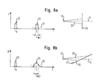
- FIGS. 8a and 8b show another possibility, on the one hand the floor recognize as such and on the other hand more information about the Gain ground.
- FIGS. 8a and 8b shows one at a time t0 from the laser scanner 13 emitted radiation pulse 23, the after Reflection on a surface 35 at a later time t1 as a reflection pulse 25 is received.
- the shape of the reflection pulse 25 and in particular in a predetermined threshold 31 measured width W is due to the expansion of the laser beam 29 from the angle between the scanning plane 15, in FIG which the beam 29 is emitted, and the respective reflective Surface 35 dependent. Since inclined with respect to the scanning plane 15 Reflection surface 35 of FIG. 8b, the front of the expanded beam 29th impinges on the reflection surface 35 at different times, is the Width W2 of the relevant reflection pulse 25 is greater than the width W1 of the perpendicular to the scanning plane 15 extending reflection surface 35 reflected pulse 25 of FIG. 8a.
Abstract
Description
Die Erfindung betrifft ein Verfahren zur Bodenerkennung mittels wenigstens einer an einem Fahrzeug angebrachten optoelektronischen Erfassungseinrichtung.The invention relates to a method for detecting soil by means of at least a vehicle-mounted opto-electronic detection device.
Optoelektronische Erfassungseinrichtungen wie beispielsweise Videokameras und Laserscanner werden in Verbindung mit Fahrzeugen dazu verwendet, die Umgebung des Fahrzeuges zu überwachen und im Überwachungsbereich befindliche Objekte zu erkennen und gegebenenfalls zu verfolgen. Hierzu ist es erforderlich, den Boden als solchen zu erkennen und von "echten" Objekten wie insbesondere anderen Verkehrsteilnehmern unterscheiden zu können, um beispielsweise unnötige Bremsvorgänge zu vermeiden, die versehentlich ausgelöst werden können, wenn eine beispielsweise in horizontaler Richtung "blickende" Erfassungseinrichtung aufgrund einer Nickbewegung des Fahrzeuges vorübergehend auf die Fahrbahn gerichtet ist und diese irrtümlich als ein vermeintlicher, in Fahrtrichtung vor dem Fahrzeug befindlicher Gegenstand detektiert wird.Opto-electronic detection devices such as video cameras and laser scanners are used in conjunction with vehicles used to monitor the environment of the vehicle and in the surveillance area to recognize objects located and, where appropriate, to follow. For this it is necessary to recognize the soil as such and of "real" objects, in particular other road users to distinguish, for example, unnecessary braking to avoid that can be accidentally triggered when an example in the horizontal direction "looking" detection device due to a pitching motion of the vehicle temporarily on the roadway is addressed and this mistakenly considered a supposed, in Direction of travel in front of the vehicle befindlicher object is detected.
Aufgabe der Erfindung ist es, ein Bodenerkennungsverfahren der eingangs genannten Art zu schaffen, mit dem auf möglichst zuverlässige Weise der Boden von anderen Objekten unterschieden werden kann.The object of the invention is to provide a soil detection method of the initially to create said type, with the most reliable way of Floor can be distinguished from other objects.
Die Lösung dieser Aufgabe erfolgt durch die Merkmale des Anspruchs 1 und insbesondere dadurch, daß mit der optoelektronischen Erfassungseinrichtung in einen Überwachungsbereich insbesondere gepulste elektromagnetische Strahlung ausgesandt und aus dem Überwachungsbereich reflektierte Strahlung empfangen und ausgewertet wird, daß die Strahlung in wenigstens zwei verschiedenen Abtastebenen ausgesandt wird, und daß die in zumindest einer der Abtastebenen reflektierte Strahlung bei der Auswertung auf das Vorhandensein zumindest eines vorgegebenen charakteristischen Bodenmerkmals hin untersucht wird.The solution of this object is achieved by the features of claim 1 and in particular the fact that with the optoelectronic detection device in a surveillance area in particular pulsed electromagnetic Radiation emitted and out of the surveillance area reflected radiation is received and evaluated that the radiation is emitted in at least two different scanning planes, and that the radiation reflected in at least one of the scanning planes in the Evaluation on the presence of at least one predetermined characteristic Soil characteristic is examined.
Erfindungsgemäß wird die elektromagnetische Strahlung in mehreren Abtastebenen ausgesandt, wobei wenigstens zwei Abtastebenen voneinander verschieden sind. Die Aussendung von Strahlung in wenigstens zwei verschiedenen Abtastebenen eröffnet grundsätzlich die vorteilhafte Möglichkeit einer dreidimensionalen oder quasi-dreidimensionalen Abtastung, da in jeder Entfernung innerhalb der Reichweite der verschiedenen Abtastebenen unterschiedliche Höhenniveaus abgetastet werden. Die Verwendung verschiedener Abtastebenen minimiert außerdem die Zeit, in der das Fahrzeug aufgrund eines nicht dem Normalbetrieb entsprechenden Momentanverhaltens - z. B. aufgrund von Nick- oder Wankbewegungen - "blind" ist, da zumindest eine Abtastebene auch dann noch brauchbare Informationen liefert, wenn eine oder mehrere Abtastebenen z. B. aufgrund einer Bodenwelle "in den Himmel blicken".According to the invention, the electromagnetic radiation in several Scanned planes emitted, wherein at least two scanning planes from each other are different. The emission of radiation in at least two different scanning levels basically opens up the advantageous possibility a three-dimensional or quasi-three-dimensional scan, because at any distance within the range of different scanning planes different height levels are sampled. The usage Different scanning levels also minimize the time in which the vehicle due to a non-normal operation Instantaneous behavior - eg. B. due to pitching or rolling movements - "blind" is because at least one scanning level still useful Information provides when one or more scan planes z. B. due a bump into the sky.
Erfindungsgemäß ist ferner vorgesehen, daß wenigstens ein charakteristisches Bodenmerkmal vorgegeben wird, das bei der Auswertung der aus dem Überwachungsbereich reflektierten Strahlung herangezogen wird. Dabei wird die in zumindest einer der Abtastebenen reflektierte Strahlung daraufhin untersucht, ob die in der reflektierten Strahlung enthaltenen Informationen auf das Vorhandensein des zumindest einen charakteristischen Bodenmerkmals hindeuten. Wenn bei der Auswertung das Vorhandensein wenigstens eines charakteristischen Bodenmerkmals erkannt wird, dann kann an eine angeschlossene Auswerteeinheit ein entsprechendes Signal gegeben werden, woraufhin beispielsweise mit Hilfe einer zentralen Steuereinrichtung geeignete Maßnahmen ergriffen werden können. Diese Maßnahmen können darin bestehen, die Auswertung der insgesamt aus dem Überwachungsbereich empfangenen Strahlung zu ergänzen und die Erfassung der Szenerie, in der sich das Fahrzeug momentan befindet, auf der Basis der durch die Bodenerkennung gewonnenen Informationen zu verbessern. Es ist ferner möglich, aktiv in den Fahrbetrieb des Fahrzeugs oder in den Betrieb einzelner Fahrzeugeinrichtungen einzugreifen.According to the invention it is further provided that at least one characteristic Floor characteristic is specified, which in the evaluation of the radiation reflected radiation is used. In this case, the radiation reflected in at least one of the scanning planes becomes then examined whether those contained in the reflected radiation Information on the presence of at least one characteristic Indicate soil characteristic. If in the evaluation the presence recognized at least one characteristic soil feature is, then can be connected to a connected evaluation a corresponding Be given signal, whereupon, for example, with the help of a appropriate measures can be taken central control device. These measures may consist of the evaluation of the total radiation received from the surveillance area complement and capture the scenery in which the vehicle is currently located on the basis of the ground detection To improve information. It is also possible to be active in the Driving the vehicle or in the operation of individual vehicle equipment intervene.
Erfindungsgemäß wird somit unter Verwendung wenigsten zweier verschiedener Abtastebenen, die mittels einer oder mehrerer optoelektronischer Erfassungseinrichtungen erzeugt werden, von charakteristischen Eigenschaften Gebrauch gemacht, die das Objekt "Boden" von "echten" Objekten, wie beispielsweise anderen Verkehrsteilnehmern, unterscheidet.Thus, according to the invention, using at least two different ones Scanning planes, which by means of one or more optoelectronic Detecting devices are generated by characteristic Properties made use of the object "ground" of "real" Objects, such as other road users.
Vorzugsweise handelt es sich bei der optoelektronischen Erfassungseinrichtung um einen Laserscanner, der zur Aussendung von Strahlung in wenigstens einer Abtastebene ausgebildet ist und für jeden innerhalb der Abtastebene ausgesandten Abtaststrahl nach dem Prinzip der Lichtlaufzeitmessung einen Entfernungswert und für diesen Entfernungswert einen Winkelwert bezogen auf eine vorgegebene Achse liefert. Der Winkelbereich, über den die Abtastung erfolgt, kann grundsätzlich beliebig gewählt werden und insbesondere bis zu 360° betragen. Bei der Verwendung von Laserscannern, die zur Aussendung lediglich einer einzigen Abtastebene ausgelegt sind, können wenigstens zwei derartige Laserscanner derart am Fahrzeug angebracht werden, daß deren Abtastebenen gegeneinander verkippt sind.Preferably, the optoelectronic detection device to a laser scanner, which is responsible for the emission of radiation in at least one scanning plane is formed and for each within the Scanning plane emitted scanning beam according to the principle of the light transit time measurement a distance value and for this distance value one Angle value related to a given axis supplies. The angular range, can be selected in principle arbitrary over the sampling and in particular up to 360 °. When using Laser scanners that transmit only one scan plane are designed, at least two such laser scanner so on Vehicle are mounted, that their scanning planes against each other are tilted.
In einer bevorzugten Ausführungsform der Erfindung wird wenigstens eine optoelektronische Erfassungseinrichtung, insbesondere wenigstens ein Laserscanner verwendet, die bzw. der zur Aussendung von Strahlung in mehreren verschiedenen Abtastebenen ausgebildet ist. Eine einzige derartige, zur Aussendung mehrerer verschiedener Abtastebenen fähige Erfassungseinrichtung reicht für das erfindungsgemäße Bodenerkennungsverfahren prinzipiell aus. Bevorzugt weist diese Erfassungseinrichtung lediglich eine einzige Strahlungsquelle insbesondere in Form einer Laserdiode auf.In a preferred embodiment of the invention, at least an opto-electronic detection device, in particular at least a laser scanner used to emit radiation is formed in several different scanning planes. A single one Such, for the transmission of several different scanning levels capable Detection device is sufficient for the soil detection method according to the invention in principle. Preferably, this detection device only a single radiation source, in particular in the form of a Laser diode on.
Gemäß einer weiteren bevorzugten Variante des erfindungsgemäßen Verfahrens ist vorgesehen, daß wenigstens eine optoelektronische Erfassungseinrichtung, insbesondere wenigstens ein Laserscanner, verwendet wird, die bzw. der für in zumindest einer Abtastebene ausgesandte Strahlung wenigstens eine Strahlungsumlenkeinrichtung aufweist, über die wenigstens eine zusätzliche Abtastebene erzeugt wird.According to another preferred variant of the invention Method is provided that at least one opto-electronic detection device, in particular at least one laser scanner used is, the or for in at least one scanning plane emitted radiation has at least one Strahlungsumlenkeinrichtung over which at least one additional scanning plane is generated.
Bei der Strahlungsumlenkeinrichtung kann es sich beispielsweise um einen oder mehrere Planspiegel handeln. Mittels derartiger Umlenkeinrichtungen kann ein Teil einer - auch als Hauptabtastebene - bezeichneten Abtastebene gezielt in bestimmte Richtungen gelenkt werden. Durch entsprechende Ausrichtung der Umlenkeinrichtungen kann dabei grundsätzlich jede beliebige Relativorientierung zwischen den einzelnen Abtastebenen realisiert werden. The radiation deflecting device may be, for example act one or more plane mirrors. By means of such deflecting devices may be a part of one, also called the main scan plane Scanning plane are directed specifically in certain directions. By appropriate orientation of the deflectors can basically any relative orientation between the individual scan planes will be realized.
Die Verwendung von Strahlungsumlenkeinrichtungen in Verbindung mit optoelektronischen Erfassungseinrichtungen und insbesondere Laserscannern ist in der am 05.06.2001 eingereichten deutschen Patentanmeldung 101 27 204 beschrieben. Auf den Inhalt dieser Anmeldung wird hiermit ausdrücklich Bezug genommen.The use of radiation deflectors in conjunction with optoelectronic detection devices and in particular laser scanners is in the filed on 05.06.2001 German patent application 101 27 204. On the content of this application will hereby incorporated by reference.
Des weiteren wird erfindungsgemäß vorgeschlagen, daß die Abtastung in mehreren verschiedenen Abtastebenen aus unterschiedlichen Richtungen erfolgt. Hierdurch ist es beispielsweise möglich, eine Region von besonderem Interesse, insbesondere den Boden in Fahrtrichtung vor dem Fahrzeug oder seitlich des Fahrzeugs, gleichzeitig aus mehreren Richtungen zu "betrachten".Furthermore, the invention proposes that the sampling in several different scanning planes from different directions he follows. This makes it possible, for example, a region of special Interest, especially the ground in the direction of travel in front of the vehicle or side of the vehicle, simultaneously from several directions too "consider".
Ferner ist es erfindungsgemäß möglich, daß wenigstens zwei optoelektronische Erfassungseinrichtungen, insbesondere Laserscanner, verwendet werden, die jeweils zur Aussendung von Strahlung in einer einzigen Abtastebene ausgebildet sind und derart betrieben werden, daß zumindest zwei Abtastebenen voneinander verschieden sind.Furthermore, it is possible according to the invention that at least two optoelectronic Detecting devices, in particular laser scanner used each to emit radiation in a single scan plane are formed and operated so that at least two scanning planes are different from each other.
Erfindungsgemäß können mehrere charakteristische Bodenmerkmale vorgegeben werden, die - sofern sie einander nicht widersprechen - bei der Auswertung der empfangenen Strahlung gemeinsam berücksichtigt werden können, wodurch eine besonders zuverlässige Bodenerkennung gewährleistet ist.According to the invention, several characteristic soil features provided that they do not contradict each other in the Evaluation of the received radiation are considered together which ensures a particularly reliable floor detection is.
In einem Ausführungsbeispiel der Erfindung wird vorgeschlagen, daß als Bodenmerkmal wenigstens eine charakteristische Form von Bodenlinien vorgegeben wird, die jeweils aus in einer Abtastebene empfangenen Bodenreflexionen gebildet werden. Typische Bodenlinienformen, die beispielsweise empirisch bestimmt und in einem Speicher einer angeschlossenen Auswerteeinheit abgelegt werden können, werden hierbei zur Bodenerkennung herangezogen. Linien, die bei der Auswertung empfangener Bodenreflexionen erzeugt werden, können im Rahmen eines Auswertealgorithmus daraufhin untersucht werden, wie gut sie mit einer oder mehreren vorgegebenen charakteristischen Bodenlinienformen übereinstimmen.In one embodiment of the invention, it is proposed that as Soil feature at least one characteristic shape of bottom lines is given, each of which received in a scanning plane ground reflections be formed. Typical floor-line forms, for example determined empirically and in a memory of a connected Evaluation unit can be stored, in this case for soil detection used. Lines received during evaluation Soil reflections can be generated as part of an evaluation algorithm They then examine how well they are with one or more match given characteristic bottom line shapes.
Des weiteren ist es erfindungsgemäß möglich, daß als Bodenmerkmal die Position zumindest einer eine charakteristische Form aufweisenden, aus in einer Abtastebene empfangenen Bodenreflexionen gebildeten Bodenlinie relativ zur Erfassungseinrichtung vorgegeben wird.Furthermore, it is possible according to the invention that the ground feature Position of at least one having a characteristic shape, from bottom line received floor reflections received in a scan plane is specified relative to the detection device.
Hierbei wird der Umstand ausgenutzt, daß beispielsweise bei bekannter Anbauposition und Ausrichtung der Erfassungseinrichtung das Objekt "Boden" nur in bestimmten Entfernungen vom Fahrzeug bzw. von der Erfassungseinrichtung detektiert werden kann. Solche bei der Auswertung von Reflexionen gebildete Linien, die dieses Positions- oder Entfernungskriterium nicht erfüllen, kommen dann im Rahmen der Auswertung als "Boden" nicht in Frage. Informationen über das Momentanverhalten des Fahrzeugs, insbesondere bei Brems- oder Beschleunigungsvorgängen, Kurvenfahrten und/oder ungleichmäßigen Gewichtsverteilungen, können im Rahmen dieser Auswertung mit herangezogen werden.Here, the fact is exploited that, for example, if known Mounting position and orientation of the detection device the object "Ground" only at certain distances from the vehicle or the Detection device can be detected. Such in the evaluation lines formed by reflections, this position or distance criterion do not meet, then come in the context of the evaluation as "Ground" out of the question. Information about the instantaneous behavior of the Vehicle, in particular during braking or acceleration, Cornering and / or uneven weight distributions, can be included in the evaluation.
Ferner wird erfindungsgemäß vorgeschlagen, das als Bodenmerkmal wenigstens ein charakteristisches Bodenmuster vorgegeben wird, dessen Bodenlinien aus in mehreren verschiedenen Abtastebenen empfangenen Bodenreflexionen gebildet werden. Hierbei kann das Objekt "Boden" beispielsweise dadurch erkannt werden, daß zwei oder mehrere unter einem bekannten Winkel auseinander laufende Abtastebenen in unterschiedlichen Entfernungen auf dem Boden auftreffen, was bei der Auswertung der empfangenen Reflexionen zu einem charakteristischen Scanbild führt, das sich beispielsweise von demjenigen unterscheidet, das bei Auftreffen der Abtastebenen auf eine senkrecht auf dem Boden stehende Wand oder auf das Heck eines vorausfahrenden LKW detektiert werden würde.Furthermore, the invention proposes that as a soil feature at least one characteristic ground pattern is given, whose Ground lines received from several different scan planes Floor reflections are formed. Here, the object "ground", for example be recognized that two or more under one well-known angles apart scanning planes in different Distances hit the ground, resulting in the evaluation of received reflections leads to a characteristic scan image, the For example, it differs from the one that hitting the Scan planes on a vertical wall or on the ground the rear of a preceding truck would be detected.
Gemäß einer weiteren Ausführungsform der Erfindung wird als Bodenmerkmal das charakteristische zeitliche Verhalten wenigstens einer insbesondere eine charakteristische Form aufweisenden Bodenlinie bei aufeinanderfolgenden Abtastvorgängen vorgegeben.According to another embodiment of the invention is as a soil feature the characteristic temporal behavior of at least one in particular a characteristic shape bottom line in successive Specified scanning.
Diese Variante nutzt die Erkenntnis aus, daß sich die bei aufeinanderfolgenden Abtastvorgängen in der gleichen Abtastebene gemessenen Entfernungen von Bodenreflexionen z.B. bei Auftreten starker Steigungen bzw. Gefällen oder bei starken Nick- oder Wankbewegungen des Fahrzeuges sehr schnell und insbesondere sprungartig von einem Abtastvorgang zum nächsten ändern. Der Boden "springt" gewissermaßen auf das Fahrzeug zu bzw. vom Fahrzeug weg, was bei "echten" Objekten wie beispielsweise anderen Verkehrsteilnehmern nicht der Fall ist.This variant exploits the knowledge that the successive Scans in the same scanning plane measured distances of ground reflections e.g. when strong gradients or Gradients or with strong pitching or rolling movements of the vehicle very fast and especially jump of a scan to next change. The floor "jumps" to a certain extent on the vehicle to or away from the vehicle, which is true for "real" objects such as other road users is not the case.
Gemäß einer weiteren Ausführungsform der Erfindung wird aus wenigstens einer eine charakteristische Form aufweisenden Bodenlinie auf den Verlauf des Bodens geschlossen. Insbesondere wird bei einer geraden Bodenlinie auf einen ebenen Boden geschlossen. Erfindungsgemäß kann somit nicht nur das Objekt "Boden" als solches erkannt, sondern es können außerdem nähere Informationen über den erkannten Boden gewonnen werden.According to a further embodiment of the invention, at least a characteristic shape having bottom line on the Closed course of the floor. In particular, in a straight Ground line closed on a level ground. According to the invention Thus, not only the object "ground" recognized as such, but it can also obtained more information about the detected soil become.
Die Erfindung schlägt des weiteren vor, aus wenigstens einer eine charakteristische Form aufweisenden Bodenlinie auf den Winkel zwischen der Abtastebene und dem Boden, insbesondere auf die Größe von Steigungen und Gefällen, zu schließen. Dies erfolgt insbesondere dadurch, daß die Steigung einer bei der Auswertung ermittelten charakteristischen Bodenlinie ausgewertet wird.The invention further proposes, from at least one characteristic Shape having ground line on the angle between the Scanning plane and the ground, especially on the size of slopes and slopes, close. This is done in particular by the fact that the Slope of a characteristic ground line determined during the evaluation is evaluated.
Ferner schlägt die Erfindung vor, daß aus wenigstens einer charakteristischen Unregelmäßigkeit oder Sprungstelle innerhalb einer eine charakteristische Form aufweisenden Bodenlinie auf das Vorhandensein einer Bodenunebenheit geschlossen wird. Hierbei wird die Erkenntnis ausgenutzt, daß bei geeigneter Orientierung der jeweiligen Abtastebene Bodenunebenheiten wie beispielsweise eine Bordsteinkante zu einer Unregelmäßigkeit oder Sprungstelle in einer charakteristischen Bodenlinie führen, die bei ebenem Boden einen stetigen Verlauf aufweisen würde. Die Unregelmäßigkeit oder Sprungstelle kann bei entsprechender Orientierung der Abtastebene insbesondere einen Z-förmigen Verlauf aufweisen.Furthermore, the invention proposes that at least one characteristic Irregularity or discontinuity within a characteristic Form having ground line on the presence of a Uneven ground is closed. Here, the knowledge is exploited, that with appropriate orientation of the respective scanning plane uneven floors such as a curb to an irregularity or jump in a characteristic ground line, which would have a steady course on even ground. The Irregularity or discontinuity can be with appropriate orientation the scanning plane in particular have a Z-shaped course.
Durch eine geeignete Transformation oder Projektion von die Bodenreflexionen repräsentierenden Meßwerten im Rahmen der Auswertung kann gemäß einer weiteren Ausführungsform der Erfindung durch Auswerten des Verlauf der Unregelmäßigkeit oder Sprungstelle das Profil der Bodenunebenheit bestimmt oder auf die Höhe oder Tiefe der Bodenunebenheit geschlossen werden. Hierdurch kann beispielsweise nicht nur das Vorhandensein einer Bordsteinkante an sich ermittelt, sondern außerdem deren Höhe gemessen werden.Through a suitable transformation or projection of the ground reflections representing measured values in the context of the evaluation can according to another embodiment of the invention by evaluating the course of the irregularity or discontinuity the profile of the ground unevenness determined or on the height or depth of the ground unevenness getting closed. As a result, for example, not only the presence a curb on itself, but also whose height is measured.
Die Erkennung von Bordsteinkanten oder anderen die Fahrbahn begrenzenden bzw. den Fahrbahnverlauf wiedergebenden Objekten mittels des erfindungsgemäßen Bodenerkennungsverfahrens kann in vorteilhafter Weise im Rahmen eines Algorithmus zur Erkennung des Fahrbahnverlaufs eingesetzt werden.The detection of curbs or other limiting the road or the road course reproducing objects by means of The soil detection method according to the invention can advantageously Way as part of an algorithm for detecting the course of the road be used.
In einer weiteren bevorzugten praktischen Ausgestaltung der Erfindung werden eine charakteristische Form aufweisende Bodenlinien jeweils durch wenigstens eine Strahlungsumlenkeinrichtung erzeugt. Vorzugsweise werden wenigstens zwei Abtastebenen erzeugt, die derart unterschiedlich zur Fahrtrichtung orientiert sind, daß zwei unterschiedlich orientierte und bevorzugt einander kreuzende Bodenlinien erzeugt werden. Die Abtastebenen sind vorzugsweise symmetrisch zur Fahrtrichtung des Fahrzeugs orientiert.In a further preferred practical embodiment of the invention become a characteristic shape having ground lines respectively generated by at least one radiation deflecting device. Preferably At least two scanning planes are generated, which are so different are oriented to the direction of travel, that two different oriented and preferably intersecting floor lines are generated. The scanning planes are preferably symmetrical to the direction of travel of the Vehicle oriented.
Auf diese Weise wird ein besonders charakteristisches und daher im Rahmen der Auswertung vergleichsweise leicht erkennbares Bodenmuster erzeugt, aus dem durch Auswerten des Verlaufs der Bodenlinien nähere Informationen über den Boden gewonnen werden können.In this way becomes a particularly characteristic and therefore in the Within the scope of the evaluation comparatively easily recognizable soil pattern generated, from which by evaluating the course of the bottom lines closer Information about the soil can be obtained.
Gemäß einer weiteren bevorzugten Ausführungsform der Erfindung wird vorgeschlagen, daß als Bodenmerkmal der erstmalige Empfang solcher Reflexionen in zumindest einer Abtastebene vorgegeben wird, die nicht von einem Objekt stammen können, das zuvor mit dieser und/oder zumindest einer anderen Abtastebene als nicht Boden bildendes Objekt erkannt worden wäre.According to another preferred embodiment of the invention proposed that as a ground feature of the first-time reception of such Reflections in at least one scanning level is given, not from can come from an object previously with this and / or at least detected as a non-ground forming object another scanning plane would have been.
Hierbei wird die Erkenntnis genutzt, daß - zumindest bei normalem Fahrbetrieb - "echte" Objekte wie z. B. andere Verkehrsteilnehmer "nicht vom Himmel fallen", sondern zuvor mittels zumindest einer Abtastebene derart rechtzeitig erkannt werden, daß erstmalig empfangene Reflexionen, die keinem der zuvor erkannten "echten" Objekte zugeordnet werden können, zumindest mit einer gewissen Wahrscheinlichkeit als vom Boden stammend angesehen werden müssen.Here, the knowledge is used that - at least during normal driving - "real" objects such. B. other road users "not from Fall sky ", but previously by means of at least one scanning plane in such a way be recognized in time that the first received reflections, the can not be assigned to any of the previously recognized "real" objects, at least with some probability as coming from the ground must be considered.
Das insbesondere bei starken Steigungen oder bei vergleichsweise starken Nick- oder Wankbewegungen typische plötzliche Auftauchen des Objekts "Boden" kann bei entsprechender Vorgabe dieses charakteristischen Bodenmerkmals erfindungsgemäß folglich erkannt werden. Informationen über das Momentanverhalten des Fahrzeuges können zur Stützung dieser im Rahmen der Auswertung getroffenen Entscheidung herangezogen werden.This is especially the case for steep gradients or comparatively strong Pitching or rolling typical sudden appearance of the object "Soil" may, with appropriate specification of this characteristic Soil feature according to the invention thus be recognized. information about the instantaneous behavior of the vehicle can support this used in the evaluation become.
Des weiteren schlägt die Erfindung vor, als Bodenmerkmal die charakteristische Form und/oder Breite solcher Bodenreflexionspulse vorzugeben, die bei einem von 90° verschiedenen Winkel zwischen der Abtastebene und dem Boden empfangen werden.Furthermore, the invention proposes, as a characteristic of the soil Specify the shape and / or width of such floor reflection pulses, at an angle other than 90 ° between the scanning plane and the ground.
Diese Variante nutzt die Erkenntnis, daß die von einer geneigten Fläche wie beispielsweise einer in Fahrtrichtung vor dem Fahrzeug liegenden, ansteigenden Fahrbahn reflektierten Strahlungspulse eine andere Form und/oder Breite aufweisen als solche Reflexionspulse, die von einer senkrecht auf dem Boden stehenden Wand, z. B. dem Heck eines LKW, stammen.This variant makes use of the knowledge that the of an inclined surface such as in front of the vehicle in the direction of travel, rising roadway reflected radiation pulses of a different shape and / or have width as such reflection pulses from a perpendicular on the floor standing wall, z. B. the rear of a truck come.
Die Erfindung schlägt des weiteren vor, daß aus der charakteristischen Form und/oder Breite der Bodenreflexionspulse der Winkel zwischen der Abtastebene und dem Boden bestimmt wird. Hierdurch läßt sich beispielsweise die Größe von Steigungen und Gefällen berechnen.The invention further proposes that from the characteristic Shape and / or width of the bottom reflection pulses of the angle between the Scanning plane and the ground is determined. This allows, for example calculate the size of slopes and slopes.
In einer weiteren bevorzugten Ausführungsform der Erfindung ist zumindest eine optoelektronische Erfassungseinrichtung, insbesondere wenigstens ein Laserscanner, vorgesehen, mit dem die Strahlung nach Art eines Fächers gleichzeitig in mehreren Abtastebenen ausgesandt wird.In a further preferred embodiment of the invention is at least an opto-electronic detection device, in particular at least a laser scanner, provided with the radiation in the manner of a Fan is sent simultaneously in several scanning levels.
Besonders bevorzugt ist es, wenn gemäß einer weiteren Variante der Erfindung wenigstens eine Boden-Abtastebene vorgesehen wird, die gezielt auf den Boden in einer Entfernung von der Erfassungseinrichtung gerichtet ist, aus der bei normalem Fahrbetrieb Bodenreflexionen erwartet werden.It is particularly preferred if according to another variant of the Invention is provided at least one bottom scanning plane, the targeted directed to the ground at a distance from the detection device is expected from the normal driving ground reflections.
Hierbei wird nicht nur die in zumindest einer der Abtastebenen reflektierte Strahlung daraufhin untersucht, ob zumindest ein vorgegebenes charakteristisches Bodenmerkmal vorhanden ist, sondern es wird gezielt wenigstens eine Boden-Abtastebene "spendiert", die ausschließlich für die Bodenerkennung vorgesehen ist, d. h. eine der Abtastebenen wird für die Bodenerkennung "abgestellt".Not only is this reflected in at least one of the scan planes Radiation then examines whether at least one predetermined characteristic Soil feature is present, but it is targeted at least a soil scanning plane "donated", exclusively for soil detection is provided, d. H. one of the scan planes will be for the Ground detection "turned off".
Dabei ist bevorzugt vorgesehen, daß die Ausrichtung der Erfassungseinrichtung automatisch derart verändert wird, daß die mit der Boden-Abtastebene gemessene Entfernung zumindest bei einem als normal eingestuften Fahrbetrieb konstant ist.It is preferably provided that the orientation of the detection device is automatically changed so that the with the bottom-scanning plane measured distance at least one as normal classified driving is constant.
Hierbei dient die Boden-Abtastebene gewissermaßen als ein "Stützfuß" für die Erfassungseinrichtung, der eine gleichbleibende Orientierung der übrigen Abtastebenen insbesondere auch dann sicherstellt, wenn das Fahrzeug Nick- oder Wankbewegungen ausführt oder im Begriff ist, eine Steigung oder ein Gefälle zu befahren. Die Verwendung einer gezielt zur Bodenerkennung dienenden Boden-Abtastebene eignet sich insbesondere für die Realisierung einer automatischen oder dynamischen Nick- und Wankwinkelkompensation.Here, the bottom-scanning plane serves as a kind of "support foot" for the detection device having a constant orientation of the remaining scanning planes in particular also ensures if the Vehicle is pitching or rolling or is about to start To climb or descend. The use of a targeted to Floor detection plane serving ground detection is particularly suitable for the realization of an automatic or dynamic pitch and Wankwinkelkompensation.
Besonders bevorzugt ist es, wenn gemäß einer Variante der Erfindung die Ausrichtung der Erfassungseinrichtung durch Nachführen einer Fahrzeugeinrichtung verändert wird, an der die Erfassungseinrichtung angebracht ist.It is particularly preferred if, according to a variant of the invention, the Alignment of the detection device by tracking a vehicle device is changed, to which the detection device attached is.
Hierbei kann die Erfassungseinrichtung folglich dafür eingesetzt werden, eine gleichbleibende Orientierung der betreffenden Fahrzeugeinrichtung relativ zum Boden zu gewährleisten, und zwar unabhängig von der Lage des Fahrzeuges relativ zum Boden. Von besonderem Vorteil ist diese Variante der Erfindung dann, wenn es sich bei der Fahrzeugeinrichtung um einen Fahrzeugscheinwerfer handelt. Eine grundsätzlich in jeder beliebigen Fahrsituation gleichbleibende Ausrichtung der Fahrzeugscheinwerfer relativ zum Boden kann auf diese Weise durch die Erfindung sichergestellt werden. In this case, the detection device can consequently be used for a constant orientation of the relevant vehicle device relative to the ground, regardless of location of the vehicle relative to the ground. Of particular advantage is this Variant of the invention, when it comes to the vehicle device is about a vehicle headlight. A basically in everyone any driving situation consistent alignment of the vehicle headlights relative to the ground can in this way by the invention be ensured.
Die Erfindung schlägt des weiteren vor, für die Auswertung der empfangenen Strahlung solche Zusatzinformationen über das Momentanverhalten des Fahrzeuges, insbesondere bei Brems- oder Beschleunigungsvorgängen, Kurvenfahrten und/oder ungleichmäßigen Gewichtsverteilungen, heranzuziehen, die zu einer Abweichung der normalen Ausrichtung des Fahrzeuges auf dem Boden führen.The invention further proposes for the evaluation of the received Radiation such additional information about the instantaneous behavior the vehicle, in particular during braking or acceleration, Cornering and / or uneven weight distributions, which leads to a deviation from the normal orientation of the Lead vehicle on the ground.
Die Erfindung betrifft außerdem die Verwendung einer oder mehrerer optoelektronischer Erfassungseinrichtungen, insbesondere eines oder mehrere Laserscanner, mit denen insbesondere gepulste elektromagnetische Strahlung in wenigstens zwei verschiedenen Abtastebenen ausgesandt und aus einem Überwachungsbereich reflektierte Strahlung empfangen und ausgewertet wird, in Verbindung mit einem Fahrzeug zur Bodenerkennung gemäß einem Verfahren, wie es vorstehend dargelegt ist.The invention also relates to the use of one or more optoelectronic detection devices, in particular one or several laser scanners, with which in particular pulsed electromagnetic Radiation emitted in at least two different scanning planes and receive radiation reflected from a surveillance area and is evaluated in conjunction with a vehicle for Ground detection according to a method as set forth above.
Weitere bevorzugte Ausführungsformen der Erfindung sind auch in den Unteransprüchen, der Beschreibung sowie der Zeichnung angegeben.Further preferred embodiments of the invention are also in the Subclaims, the description and the drawings.
Die Erfindung wird im folgenden beispielhaft unter Bezugnahme auf die Zeichnung beschrieben. Es zeigen:
- Fig. 1, 2 und 3
- jeweils schematisch einen verschiedene Abtastebenen aufweisenden Laserscanner, und zwar jeweils in einer Draufsicht und einer Seitenansicht,
- Fig. 4, 5, 6, 7a und 7b
- verschiedene Beispiele für aus empfangenen Bodenreflexionen gebildete Bodenlinien, und
- Fig. 8a und 8b
- ein erfindungsgemäßes Prinzip zur Bodenerkennung durch Auswerten von Reflexionspulsen.
- Fig. 1, 2 and 3
- each schematically a different scanning planes having laser scanner, in each case in a plan view and a side view,
- Fig. 4, 5, 6, 7a and 7b
- various examples of bottom lines formed from received ground reflections, and
- Fig. 8a and 8b
- an inventive principle for ground detection by evaluating reflection pulses.
Die Fig. 1, 2 und 3 zeigen jeweils eine Ausführungsform eines Laserscanners
13, der mit zwei Planspiegeln 17 versehen ist, welche im am Fahrzeug
montierten Zustand vorzugsweise bezüglich der Fahrtrichtung symmetrisch
angeordnet sind.FIGS. 1, 2 and 3 each show an embodiment of a
Die vom Scanner 13 ausgesandte Strahlung wird zum einen über einen
Winkelbereich von nahezu 180° direkt in einer Hauptabtastebene 15 und
über die Spiegel 17 in zwei weiteren, jeweils einen Winkelbereich von etwa
40° abdeckenden Abtastebenen 15 ausgesandt, so daß insgesamt mit drei
verschiedenen Abtastebenen 15 gearbeitet wird.The radiation emitted by the
In dem Beispiel gemäß Fig. 1 liegen alle drei Abtastebenen 15 in einer
gemeinsamen Ebene, wodurch die effektive Abtastfrequenz erhöht wird, da
für jede Umdrehung des Scanners 13 die im Überlappungsbereich der
Abtastebenen 15 liegenden Regionen mehrfach abgetastet werden.In the example according to FIG. 1, all three scanning
Ein mehrere Abtastebenen aussendender Scanner 13 wird auch als Mehrzeilen-Scanner
bezeichnet, da ein von den Abtastebenen 15 erfaßtes Objekt
zeilenförmig abgetastet wird.A multiple scanning
In dem in Fig. 2 gezeigten Beispiel sind die beiden Spiegel 17 geringfügig,
z. B. um einige wenige Grad, gegeneinander verkippt, wodurch insgesamt
drei unterschiedlich orientierte Abtastebenen 15 erzeugt werden. In the example shown in FIG. 2, the two
In dem Beispiel gemäß Fig. 3 sind die Spiegel 17 derart orientiert, daß die
über die Spiegel 17 ausgesandten Abtastebenen einander überlappen und
im am Fahrzeug montierten Zustand und bei normal ausgerichtetem
Fahrzeug im Nahbereich vor dem Scanner 13 auf den Boden treffen.In the example of FIG. 3, the
Während die vergleichsweise leichte Spiegelverkippung gemäß Fig. 2
insbesondere eine Mehrebenen- oder Mehrzeilenabtastung ermöglicht, die
eine Nickwinkelkompensation ohne mechanisch zu bewegende Bauteile
dadurch gestattet, daß zumindest bei den meisten in der Praxis auftretenden
Nickbewegungen des Fahrzeugs - z. B. aufgrund von Bodenunebenheiten
oder Bremsvorgängen - stets zumindest eine der Abtastebenen 15
in eine Richtung "blickt", in der für die Überwachung der Fahrzeugumgebung
wichtige Objekte sicher erkannt werden, werden bei dem Beispiel
gemäß Fig. 3 die beiden über die Spiegel 17 ausgesandten Abtastebenen
15 gezielt für die Bodenerkennung eingesetzt.While the comparatively slight Spiegelverkippung shown in FIG. 2
In particular, a multilevel or multi-line scan enables
a pitch compensation without mechanical components to be moved
thereby allowing at least most of them to be used in practice
Nick movements of the vehicle - z. B. due to uneven floors
or braking operations - always at least one of the scanning planes 15
in one direction "looks", in for the surveillance of the vehicle environment
important objects are detected safely, in the example
as shown in FIG. 3, the two transmitted via the
Die erfindungsgemäße Bodenerkennung durch Überprüfen der empfangenen
Strahlung auf das Vorhandensein charakteristischer Bodenmerkmale
kann jedoch grundsätzlich für jede beliebig orientierte Abtastebene 15 und
damit nicht nur für die gezielt zur Bodenerkennung abgestellten Abtastebenen
15 gemäß Fig. 3, sondern auch für alle Abtastebenen 15 von Fig. 1
und Fig. 2 durchgeführt werden.The ground detection according to the invention by checking the received
Radiation on the presence of characteristic soil features
However, in principle for each arbitrary oriented
Fig. 4 zeigt ein typisches Scanbild, das mit einem Laserscanner 13 gemessen
wurde, wie er in Fig. 2 dargestellt ist, d. h. mit einem Laserscanner,
der nur relativ leicht verkippte Spiegel 17 aufweist. Die Laserscanner 13
arbeiten bevorzugt mit einer Wellenlänge von 905 nm (nahes IR), so daß
es sich bei den Spiegeln 17 jeweils um Infrarot-Spiegel handelt. FIG. 4 shows a typical scan image measured with a
Das Fahrzeug, an welchem der Laserscanner 13 angebracht ist, bewegt
sich in x-Richtung auf einer Fahrbahn, die mittels der beiden unteren
Abtastebenen 15 (vgl. Fig. 2) dadurch erkannt wird, daß die Bodenreflexionen
charakteristische Bodenlinien 19 detektieren. Die mittels der unteren
Abtastebene 15 detektierte Bodenlinie 19 trifft auf die Fahrbahn in
einer geringeren Entfernung vom Scanner 13 als die mittlere Abtastebene
15, die folglich die gegenüber den Fahrbahnrändern erhöhte Fahrbahn
deutlich ausgeprägter zeigt, während die obere (Haupt-)Abtastebene 15
nicht oder erst außerhalb der Reichweite des Scanners 13 auf die Fahrbahn
trifft.The vehicle on which the
Fig. 4 zeigt außerdem eine vergleichsweise "scharfe" linke Fahrbahnbegrenzung,
wie sie beispielsweise durch eine Leitplanke hervorgerufen wird,
während die rechte Fahrbahnbegrenzung, die in diesem Beispiel über die
mittlere Abtastebene 15 ermittelt wurde, von vergleichsweise "unscharfen"
Objekten, wie z. B. Gräsern oder Büschen, begrenzt wird. In einer größeren
Entfernung als derjenigen, in der die mittlere Abtastebene 15 auf die
Fahrbahn trifft, wird mittels der oberen Abtastebene 15 lediglich die vergleichsweise
"scharfe" linke Fahrbahnbegrenzung "gesehen". Bei den
innerhalb der Fahrbahnbegrenzungen gelegenen, regelmäßig angeordneten
Objekten handelt es sich um Leitpfosten.4 also shows a comparatively "sharp" left lane boundary,
as evoked by a guardrail, for example,
while the right lane boundary, which in this example over the
Zu bemerken ist ferner, daß Fig. 4 - wie auch die im folgenden beschriebenen Fig. 5, 6, 7a und 7b - Rohdaten zeigt, was bedeutet, daß jeder Punkt im Scanbild einem reflektierten Abtaststrahl entspricht. It should also be noted that Fig. 4 - as well as those described below Figs. 5, 6, 7a and 7b show raw data, which means that each Point in the scan image corresponds to a reflected scanning beam.
Fig. 4 macht deutlich, daß erfindungsgemäß eine Bodenerkennung nicht
nur über die Detektion charakteristischer Bodenlinien 19 an sich, sondern
außerdem dadurch möglich ist, daß das von den Bodenlinien 19 gebildete
charakteristische Bodenmuster als solches bei der Auswertung erkannt
wird.Fig. 4 makes it clear that according to the invention a soil detection not
only via the detection of characteristic
Fig. 5 zeigt ein Scanbild, das mit einem Scanner 13 aufgenommen wurde,
wie er in Fig. 3 dargestellt ist. Die über die vergleichsweise stark aus der
Horizontalen gekippten Spiegel 17 ausgesandten Abtastebenen 15 "blicken"
in relativ kurzer Entfernung von z. B. etwa 2 m vor dem am Fahrzeug
angebrachten Scanner 13 auf den Boden. Die in diesen Abtastebenen
15 empfangenen Reflexionen bilden ein charakteristisches Bodenmuster
in Form zweier einander kreuzender charakteristischer Bodenlinien 19.5 shows a scan image taken with a
Hierdurch ist nicht nur eine Bodenerkennung an sich möglich, sondern
aus dem Verlauf der Bodenlinien 19 können zusätzliche Informationen
gewonnen werden. So kann aus dem geraden Verlauf einer Bodenlinie 19
auf einen ebenen Boden, aus der Orientierung, d. h. hier dem positiven
Gradienten, einer Bodenlinie 19 auf das Vorhandensein einer Fahrbahnsteigung
und aus der Steigung der Bodenlinie 19 selbst auf die Größe der
Fahrbahnsteigung geschlossen werden.As a result, not only is a floor detection per se possible, but also
from the course of the
Die Steigungsberechnung kann mittels der oberen (Haupt-)Abtastebene 15
(vgl. Fig. 3) auf Plausibilität dadurch geprüft werden, daß die tatsächliche
Entfernung, in welcher die obere Abtastebene 15 auf die Fahrbahn trifft
und die im oberen Teil von Fig. 5 dargestellte, quer zur Fahrtrichtung
verlaufende Bodenlinie 19 erzeugt, mit einem Vorhersagewert verglichen
wird, der aus den einander kreuzenden Bodenlinien 19 gewonnen wird. The slope calculation can be performed by means of the upper (main) scanning plane 15
(see Fig. 3) are checked for plausibility that the actual
Distance at which the
Hierdurch kann mittels der über die Spiegel 17 ausgesandten, gezielt zur
Bodenerkennung eingesetzten Abtastebenen 15 festgestellt werden, ob es
sich bei einem mit der oberen Abtastebene 15 erkannten Objekt um den
Boden oder um ein "echtes" Objekt wie z. B. einen anderen Verkehrsteilnehmer
handelt.As a result, by means of the emitted via the
Fig. 6 zeigt eine weitere Möglichkeit zur Bestimmung von Fahrbahnsteigungen
oder - gefällen. Es handelt sich bei diesem Scanbild um eine
Projektion der Scanpunkte in die x-z-Ebene, d. h. die y-Koordinate wurde
außer acht gelassen. Die charakteristischen Bodenlinien 19, die mittels
der über die Spiegel 17 ausgesandten Abtastebenen 15 (vgl. Fig. 3) gewonnen
werden, geben die Höhe der einzelnen Scanpunkte bezogen auf die
Position des Scanners 13 am (nicht maßstabsgerecht dargestellten) Fahrzeug
11 an.FIG. 6 shows a further possibility for determining road inclinations
or - falls. This is a scanned image
Projection of scan points into the x-z plane, d. H. the y coordinate became
ignored. The characteristic
Aus dem Verlauf dieser gewissermaßen eine Seitenansicht bildenden
charakteristischen Bodenlinie 19 kann die Größe der Fahrbahnsteigung
bzw. des Fahrbahngefälles berechnet werden.From the course of this somewhat forming a side view
Fig. 7a zeigt ein Scanbild, das wiederum mit einem Laserscanner 13, wie
er in Fig. 3 dargestellt ist, aufgenommen wurde und entsprechend Fig. 5
einander kreuzende, charakteristische Bodenlinien 19 zeigt, die von den
über die Spiegel 17 ausgesandten Abtastebenen 15 stammen. Mit der
oberen, direkt ausgesandten Abtastebene 15 wird ein anderes, links vor
dem eigenen Fahrzeug befindliches Fahrzeug 33 "gesehen" und anhand
seiner charakteristischen Form erkannt. Fig. 7a shows a scan image, which in turn with a
Die von links nach rechts ansteigende Bodenlinie 19 weist eine Z-förmige
Sprungstelle 21 auf. Derartige Unregelmäßigkeiten in den charakteristischen
Bodenlinien 19 entstehen durch Abtasten von Bodenunebenheiten.
Im in Fig. 7a dargestellten Fall handelt es sich bei der Bodenunebenheit
um eine Bordsteinkante, die sich in der charakteristischen Unregelmäßigkeit
oder Sprungstelle 21 widerspiegelt.The bottom line rising from left to right 19 has a Z-shaped
Durch die in Fig. 7b gezeigte, der Darstellung in Fig. 6 entsprechenden
Projektion kann die Höhe der Bordsteinkante 21 auf einfache Weise bestimmt
werden. Hierdurch ermöglicht die Erfindung folglich nicht nur die
Bodenerkennung an sich, sondern außerdem die quantitative Bestimmung
eines Bodenprofils.By the shown in Fig. 7b, the representation in Fig. 6 corresponding
Projection can easily determine the height of
Die Fig. 8a und 8b zeigen eine weitere Möglichkeit, zum einen den Boden als solchen zu erkennen und zum anderen nähere Informationen über den Boden zu gewinnen.FIGS. 8a and 8b show another possibility, on the one hand the floor recognize as such and on the other hand more information about the Gain ground.
Die linke Darstellung in Fig. 8a und 8b zeigt jeweils einen zu einem Zeitpunkt
t0 vom Laserscanner 13 ausgesandten Strahlungspuls 23, der nach
Reflexion an einer Fläche 35 zu einem späteren Zeitpunkt t1 als Reflexionspuls
25 empfangen wird.The left-hand illustration in FIGS. 8a and 8b shows one at a time
t0 from the
Die Form des Reflexionspulses 25 und insbesondere dessen bei einer
vorgegebenen Schwelle 31 gemessene Breite W ist aufgrund der Aufweitung
des Laserstrahls 29 von dem Winkel zwischen der Abtastebene 15, in
welcher der Strahl 29 ausgesandt wird, und der jeweiligen reflektierenden
Fläche 35 abhängig. Da bei der gegenüber der Abtastebene 15 geneigten
Reflexionsfläche 35 gemäß Fig. 8b die Front des aufgeweiteten Strahls 29
zu verschiedenen Zeitpunkten auf die Reflexionsfläche 35 auftrifft, ist die
Breite W2 des betreffenden Reflexionspulses 25 größer als die Breite W1
des von der senkrecht zur Abtastebene 15 verlaufenden Reflexionsfläche
35 reflektierten Pulses 25 gemäß Fig. 8a.The shape of the
Aus dem auf diese Weise erkannten Vorhandensein einer vor dem Fahrzeug
befindlichen Schrägfläche kann - gegebenenfalls unter Berücksichtigung
von Zusatzinformationen z. B. über das Momentanverhalten des
Fahrzeuges oder über andere mittels des Laserscanners 13 erkannte
Objekte - auf eine vor dem Fahrzeug liegende Steigung geschlossen und
damit das Objekt "Boden" als solches erkannt werden. Ferner kann durch
eine Analyse des Reflexionspulses 25 der Winkel zwischen der Abtastebene
15 und dem Boden 27 berechnet und damit die Größe der Steigung
bestimmt werden.From the presence of one detected in front of the vehicle
located inclined surface can - if necessary, taking into account
additional information z. B. on the instantaneous behavior of the
Vehicle or other detected by means of the
Alle in dieser Anmeldung beschriebenen erfindungsgemäßen Möglichkeiten zur Bodenerkennung können - sofern sie einander nicht widersprechen - miteinander kombiniert und gegebenenfalls durch Zusatzinformationen ergänzt werden. All possibilities according to the invention described in this application for ground detection - if they do not contradict each other - combined with each other and, where appropriate, with additional information be supplemented.
- 1111
- Fahrzeugvehicle
- 1313
- optoelektronische Erfassungseinrichtung, Laserscanneropto-electronic detection device, laser scanner
- 1515
- Abtastebenescan
- 1717
- Strahlungsumlenkeinrichtung, SpiegelRadiation deflector, mirror
- 1919
- charakteristische Bodenliniecharacteristic ground line
- 2121
- Unregelmäßigkeit, SprungstelleIrregularity, jump
- 2323
- ausgesandter Strahlungspulsemitted radiation pulse
- 2525
- Reflexionspulsreflection pulse
- 2727
- Bodenground
- 2929
- Strahlbeam
- 3131
- Schwellethreshold
- 3333
- anderes Fahrzeuganother vehicle
- 3535
- reflektierende Flächereflective surface
Claims (23)
dadurch gekennzeichnet, daß wenigstens eine optoelektronische Erfassungseinrichtung (13), insbesondere wenigstens ein Laserscanner, verwendet wird, die zur Aussendung von Strahlung in mehreren verschiedenen Abtastebenen (15) ausgebildet ist und vorzugsweise eine einzige Strahlungsquelle insbesondere in Form einer Laserdiode aufweist. Method according to claim 1,
characterized in that at least one optoelectronic detection device (13), in particular at least one laser scanner, is used, which is designed to emit radiation in a plurality of different scanning planes (15) and preferably has a single radiation source, in particular in the form of a laser diode.
dadurch gekennzeichnet, daß wenigstens eine optoelektronische Erfassungseinrichtung (13), insbesondere wenigstens ein Laserscanner, verwendet wird, die für in zumindest einer Abtastebene (15) ausgesandte Strahlung wenigstens eine Strahlungsumlenkeinrichtung (17) aufweist, über die wenigstens eine zusätzliche Abtastebene (15) erzeugt wird.Method according to claim 1 or 2,
characterized in that at least one optoelectronic detection device (13), in particular at least one laser scanner, is used which has at least one radiation deflection device (17) for radiation emitted in at least one scanning plane (15) over which at least one additional scanning plane (15) is generated ,
dadurch gekennzeichnet, daß die Abtastung in mehreren verschiedenen Abtastebenen (15) aus unterschiedlichen Richtungen erfolgt.Method according to one of the preceding claims,
characterized in that the scanning takes place in several different scanning planes (15) from different directions.
dadurch gekennzeichnet, daß wenigstens zwei optoelektronische Erfassungseinrichtungen, insbesondere Laserscanner, verwendet werden, die jeweils zur Aussendung von Strahlung in einer einzigen Abtastebene ausgebildet sind und derart betrieben werden, daß zumindest zwei Abtastebenen voneinander verschieden sind.Method according to one of the preceding claims,
characterized in that at least two opto-electronic detection devices, in particular laser scanners, are used which are each designed to emit radiation in a single scanning plane and are operated such that at least two scanning planes are different from each other.
dadurch gekennzeichnet, daß als Bodenmerkmal wenigstens eine charakteristische Form von Bodenlinien (19) vorgegeben wird, die jeweils aus in einer Abtastebene (15) empfangenen Bodenreflexionen gebildet werden. Method according to one of the preceding claims,
characterized in that as a soil feature at least one characteristic shape of bottom lines (19) is predetermined, each of which is formed in a scanning plane (15) received ground reflections.
dadurch gekennzeichnet, daß als Bodenmerkmal die Position zumindest einer eine charakteristische Form aufweisenden, aus in einer Abtastebene (15) empfangenen Bodenreflexionen gebildeten Bodenlinie (19) relativ zur Erfassungseinrichtung (13) vorgegeben wird.Method according to one of the preceding claims,
characterized in that as a ground feature the position of at least one of a characteristic shape, formed from in a scanning plane (15) received bottom line (19) relative to the detection device (13) is specified.
dadurch gekennzeichnet, daß als Bodenmerkmal wenigstens ein charakteristisches, insbesondere von mehreren jeweils eine charakteristische Form aufweisenden Bodenlinien (19) gebildetes Bodenmuster vorgegeben wird, dessen Bodenlinien (19) aus in mehreren verschiedenen Abtastebenen (15) empfangenen Bodenreflexionen gebildet werden.Method according to one of the preceding claims,
characterized in that as a soil feature at least one characteristic, in particular of several in each case a characteristic shape having ground lines (19) formed bottom pattern is given whose bottom lines (19) formed in several different scanning planes (15) ground reflections are formed.
dadurch gekennzeichnet, daß als Bodenmerkmal das charakteristische zeitliche Verhalten wenigstens einer insbesondere eine charakteristische Form aufweisenden Bodenlinie (19) bei aufeinanderfolgenden Abtastvorgängen vorgegeben wird.Method according to one of the preceding claims,
characterized in that as a soil feature the characteristic temporal behavior of at least one in particular a characteristic shape having bottom line (19) is predetermined in successive scans.
dadurch gekennzeichnet, daß aus wenigstens einer eine charakteristische Form aufweisenden Bodenlinie (19) auf den Verlauf des Bodens geschlossen wird, wobei insbesondere bei einer geraden Bodenlinie (19) auf einen ebenen Boden geschlossen wird. Method according to one of claims 6 to 9,
characterized in that from at least one characteristic shape having bottom line (19) is closed to the course of the soil, being closed in particular at a straight bottom line (19) on a flat bottom.
dadurch gekennzeichnet, daß aus wenigstens einer eine charakteristische Form aufweisenden Bodenlinie (19) auf den Winkel zwischen der Abtastebene (15) und dem Boden, insbesondere auf die Größe von Steigungen und Gefällen, geschlossen wird.Method according to one of claims 6 to 10,
characterized in that from at least one bottom line (19) having a characteristic shape is closed to the angle between the scanning plane (15) and the ground, in particular to the size of inclines and inclines.
dadurch gekennzeichnet, daß aus wenigstens einer charakteristischen, insbesondere Z-förmigen Unregelmäßigkeit oder Sprungstelle (21) innerhalb einer eine charakteristische Form aufweisenden Bodenlinie (19) auf das Vorhandensein einer Bodenunebenheit, insbesondere einer Bordsteinkante, geschlossen wird.Method according to one of claims 6 to 11,
characterized in that from at least one characteristic, in particular Z-shaped irregularity or discontinuity (21) within a characteristic shape having bottom line (19) on the presence of a bump, especially a curb, closed.
dadurch gekennzeichnet, daß durch Auswerten des Verlaufs der Unregelmäßigkeit oder Sprungstelle (21), insbesondere mittels einer Projektion von die Bodenreflexionen repräsentierenden Meßwerten, das Profil der Bodenunebenheiten bestimmt und insbesondere auf die Höhe oder Tiefe der Bodenunebenheit geschlossen wird. Method according to claim 12,
characterized in that by evaluating the course of the irregularity or discontinuity (21), in particular by means of a projection of the soil reflections representing measured values, determines the profile of the bumps and is in particular closed on the height or depth of the bump.
dadurch gekennzeichnet, daß eine charakteristische Form aufweisende Bodenlinien (19) jeweils durch wenigstens eine Strahlungsumlenkeinrichtung (17) erzeugt werden, wobei bevorzugt wenigstens zwei Abtastebenen (15) erzeugt werden, die derart unterschiedlich und bevorzugt symmetrisch zur Fahrtrichtung orientiert sind, daß zwei unterschiedlich orientierte und bevorzugt einander kreuzende Bodenlinien (19) erzeugt werden.Method according to one of claims 6 to 13,
characterized in that a characteristic shape having bottom lines (19) are each generated by at least one Strahlungsumlenkeinrichtung (17), wherein preferably at least two scanning planes (15) are generated, which are oriented so different and preferably symmetrical to the direction of travel that two differently oriented and Preferably, intersecting bottom lines (19) are generated.
dadurch gekennzeichnet, daß als Bodenmerkmal der erstmalige Empfang solcher Reflexionen in zumindest einer Abtastebene (15) vorgegeben wird, die nicht von einem Objekt stammen können, das zuvor mit dieser und/oder zumindest einer anderen Abtastebene (15) als nicht Boden bildendes Objekt erkannt worden wäre.Method according to one of the preceding claims,
characterized in that as the ground feature of the first-time reception of such reflections in at least one scanning plane (15) is given, which can not originate from an object that previously with this and / or at least one other scanning plane (15) has been recognized as non-ground forming object would.
dadurch gekennzeichnet, daß als Bodenmerkmal die insbesondere bezüglich der in wenigstens einer Abtastebene (15) ausgesandten Strahlungspulse (23) charakteristische Form und/oder Breite (W2) solcher Bodenreflexionspulse (25) vorgegeben wird, die bei einem von 90° verschiedenen Winkel zwischen der Abtastebene (15) und dem Boden (27) empfangen werden. Method according to one of the preceding claims,
characterized in that the ground characteristic is the shape and / or width (W2) of such ground reflection pulses (25) which is characteristic, in particular, with respect to the radiation pulses (23) emitted in at least one scanning plane (15), the angle being different from 90 ° between the scanning plane (15) and the floor (27) are received.
dadurch gekennzeichnet, daß aus der charakteristischen Form und/oder Breite (W2) der Bodenreflexionspulse (25) der Winkel zwischen der Abtastebene (15) und dem Boden (27), insbesondere die Größe von Steigungen und Gefällen, bestimmt wird.Method according to claim 16,
characterized in that from the characteristic shape and / or width (W2) of the floor reflection pulses (25) the angle between the scanning plane (15) and the floor (27), in particular the size of inclines and slopes, is determined.
dadurch gekennzeichnet, daß die Strahlung nach Art eines Fächers gleichzeitig in mehreren Abtastebenen (15) ausgesandt wird.Method according to one of the preceding claims,
characterized in that the radiation in the manner of a fan at the same time in several scanning planes (15) is emitted.
dadurch gekennzeichnet, daß wenigstens eine Boden-Abtastebene (15) vorgesehen wird, die gezielt auf den Boden in einer Entfernung von der Erfassungseinrichtung (13) gerichtet ist, aus der bei normalem Fahrbetrieb Bodenreflexionen erwartet werden.Method according to one of the preceding claims,
characterized in that at least one ground scanning plane (15) is provided which is aimed at the ground at a distance from the detection means (13) from which ground reflections are expected during normal driving.
dadurch gekennzeichnet, daß insbesondere zur Nick- oder Wankwinkelkompensation die Ausrichtung der Erfassungseinrichtung (13) automatisch derart verändert wird, daß die mit der Boden-Abtastebene (15) gemessene Entfernung zumindest bei einem als normal eingestuften Fahrbetrieb konstant ist. Method according to claim 19,
characterized in that in particular for pitch or roll angle compensation, the orientation of the detection device (13) is automatically changed so that the measured with the bottom scanning plane (15) distance is constant at least in a normal rated driving operation.
dadurch gekennzeichnet, daß die Ausrichtung der Erfassungseinrichtung (13) durch Nachführen einer Fahrzeugeinrichtung, insbesondere eines Fahrzeugscheinwerfers, verändert wird, an der die Erfassungseinrichtung (13) angebracht ist.Method according to claim 20,
characterized in that the orientation of the detection device (13) by tracking a vehicle device, in particular a vehicle headlight, is changed, to which the detection device (13) is mounted.
dadurch gekennzeichnet, daß für die Auswertung der empfangenen Strahlung solche Zusatzinformationen über das Momentanverhalten des Fahrzeugs (11), insbesondere bei Brems- oder Beschleunigungsvorgängen, Kurvenfahrten und/oder ungleichmäßigen Gewichtsverteilungen, herangezogen werden, die zu einer Abweichung der normalen Ausrichtung des Fahrzeugs (11) auf dem Boden führen.Method according to one of the preceding claims,
characterized in that for the evaluation of the received radiation such additional information on the instantaneous behavior of the vehicle (11), in particular during braking or acceleration operations, cornering and / or uneven weight distributions, are used, resulting in a deviation of the normal orientation of the vehicle (11) lead on the ground.
Applications Claiming Priority (2)
| Application Number | Priority Date | Filing Date | Title |
|---|---|---|---|
| DE10141294.0A DE10141294B4 (en) | 2001-08-23 | 2001-08-23 | Ground detection method |
| DE10141294 | 2001-08-23 |
Publications (2)
| Publication Number | Publication Date |
|---|---|
| EP1286178A2 true EP1286178A2 (en) | 2003-02-26 |
| EP1286178A3 EP1286178A3 (en) | 2003-11-05 |
Family
ID=7696331
Family Applications (1)
| Application Number | Title | Priority Date | Filing Date |
|---|---|---|---|
| EP02016031A Ceased EP1286178A3 (en) | 2001-08-23 | 2002-07-18 | Method for optical ground detection |
Country Status (2)
| Country | Link |
|---|---|
| EP (1) | EP1286178A3 (en) |
| DE (1) | DE10141294B4 (en) |
Cited By (22)
| Publication number | Priority date | Publication date | Assignee | Title |
|---|---|---|---|---|
| JP2005222538A (en) * | 2004-01-26 | 2005-08-18 | Ibeo Automobile Sensor Gmbh | Method for recognizing mark on driveway |
| EP1566660A3 (en) * | 2004-02-20 | 2006-06-07 | DaimlerChrysler AG | Method for evaluating signals of a vehicle environment sensor |
| EP2113790A1 (en) * | 2008-04-18 | 2009-11-04 | BAE Systems PLC | Improvements in LIDARs |
| WO2009136184A3 (en) * | 2008-04-18 | 2010-05-06 | Bae Systems Plc | Improvements in lidars |
| EP2306217A1 (en) * | 2009-09-30 | 2011-04-06 | Sick Ag | Environment recording |
| EP2746808A1 (en) | 2012-12-18 | 2014-06-25 | Sick Ag | Opto-electronic sensor for detecting objects |
| EP2894493A1 (en) | 2014-01-10 | 2015-07-15 | Sick Ag | Optoelectronic sensor and method for detecting objects in a surveillance area |
| DE102014118149A1 (en) | 2014-12-08 | 2016-06-09 | Sick Ag | Optoelectronic sensor and method for detecting objects |
| JP2017015601A (en) * | 2015-07-02 | 2017-01-19 | シャープ株式会社 | Road surface detection device, mobile body, road surface detection method, and road surface detection program |
| EP3139361A4 (en) * | 2014-04-28 | 2018-01-10 | Hitachi Construction Machinery Co., Ltd. | Road-shoulder-detecting system and transportation vehicle for mining |
| CN108474853A (en) * | 2016-01-20 | 2018-08-31 | 罗伯特·博世有限公司 | Big lamp module, headlight, headlight system and the operation method for big lamp module |
| WO2019176667A1 (en) * | 2018-03-14 | 2019-09-19 | オムロン株式会社 | Detecting device and detecting method |
| CN110378246A (en) * | 2019-06-26 | 2019-10-25 | 深圳前海达闼云端智能科技有限公司 | Ground detection method, apparatus, computer readable storage medium and electronic equipment |
| USRE48490E1 (en) | 2006-07-13 | 2021-03-30 | Velodyne Lidar Usa, Inc. | High definition LiDAR system |
| US10983218B2 (en) | 2016-06-01 | 2021-04-20 | Velodyne Lidar Usa, Inc. | Multiple pixel scanning LIDAR |
| US11073617B2 (en) | 2016-03-19 | 2021-07-27 | Velodyne Lidar Usa, Inc. | Integrated illumination and detection for LIDAR based 3-D imaging |
| US11082010B2 (en) | 2018-11-06 | 2021-08-03 | Velodyne Lidar Usa, Inc. | Systems and methods for TIA base current detection and compensation |
| US11137480B2 (en) | 2016-01-31 | 2021-10-05 | Velodyne Lidar Usa, Inc. | Multiple pulse, LIDAR based 3-D imaging |
| US11703569B2 (en) | 2017-05-08 | 2023-07-18 | Velodyne Lidar Usa, Inc. | LIDAR data acquisition and control |
| US11808891B2 (en) | 2017-03-31 | 2023-11-07 | Velodyne Lidar Usa, Inc. | Integrated LIDAR illumination power control |
| US11885958B2 (en) | 2019-01-07 | 2024-01-30 | Velodyne Lidar Usa, Inc. | Systems and methods for a dual axis resonant scanning mirror |
| US11933967B2 (en) | 2019-08-22 | 2024-03-19 | Red Creamery, LLC | Distally actuated scanning mirror |
Families Citing this family (4)
| Publication number | Priority date | Publication date | Assignee | Title |
|---|---|---|---|---|
| DE102009016563A1 (en) | 2009-04-06 | 2009-11-19 | Daimler Ag | Obstacle i.e. cavity, detecting method for use at exit area of vehicle door of passenger car, involves determining surface profile of floor surface by displacements, and evaluating profile for detection of obstacles and/or stain of scanner |
| JP5267592B2 (en) | 2010-04-09 | 2013-08-21 | 株式会社デンソー | Object recognition device |
| DE102012207328A1 (en) * | 2012-05-03 | 2013-11-07 | Audi Ag | System for acquisition of track profile for vehicle, has control device connected with light-time cameras and determining spacing and dimensions of uneven portion of track profile based on components of vehicle |
| EP4109127B1 (en) | 2021-06-21 | 2023-05-10 | Sick Ag | Optoelectronic sensor and method for detecting objects |
Citations (1)
| Publication number | Priority date | Publication date | Assignee | Title |
|---|---|---|---|---|
| DE19536000A1 (en) * | 1995-09-28 | 1997-04-03 | Spies Martin J Dipl Ing Fh | Level setting for distance measurement devices in motor vehicles |
Family Cites Families (11)
| Publication number | Priority date | Publication date | Assignee | Title |
|---|---|---|---|---|
| CA1235773A (en) * | 1983-12-23 | 1988-04-26 | Shigeto Nakayama | Device for detecting road surface condition |
| DE3738221A1 (en) * | 1987-11-11 | 1989-06-08 | Bayerische Motoren Werke Ag | METHOD AND DEVICE FOR DETECTING THE STATE OF A ROAD |
| GB2308256B (en) * | 1995-05-02 | 2000-02-09 | Tokimec Inc | An apparatus for measuring a shape of road surface |
| DE19530281C2 (en) * | 1995-08-17 | 1999-01-07 | Johann Hipp | Device for optically detecting obstacles in front of vehicles |
| DE19720846C2 (en) * | 1997-05-17 | 2003-02-20 | Eads Deutschland Gmbh | Non-contact speed measurement system for a motor vehicle |
| DE19730414A1 (en) * | 1997-07-16 | 1999-01-21 | Opel Adam Ag | Method to judge condition of roadway in advance |
| EP0913751B1 (en) * | 1997-11-03 | 2003-09-03 | Volkswagen Aktiengesellschaft | Autonomous vehicle and guiding method for an autonomous vehicle |
| DE19757849C5 (en) * | 1997-12-24 | 2013-11-21 | Sick Ag | Scanner and device for the optical detection of obstacles, and their use |
| JP3420049B2 (en) * | 1997-12-27 | 2003-06-23 | 本田技研工業株式会社 | Vehicle object detection device |
| DE19934670B4 (en) * | 1999-05-26 | 2004-07-08 | Robert Bosch Gmbh | Object detection system |
| DE19932094A1 (en) * | 1999-07-09 | 2001-01-25 | Daimler Chrysler Ag | Multi-sensory, predictive road condition detection |
-
2001
- 2001-08-23 DE DE10141294.0A patent/DE10141294B4/en not_active Expired - Lifetime
-
2002
- 2002-07-18 EP EP02016031A patent/EP1286178A3/en not_active Ceased
Patent Citations (1)
| Publication number | Priority date | Publication date | Assignee | Title |
|---|---|---|---|---|
| DE19536000A1 (en) * | 1995-09-28 | 1997-04-03 | Spies Martin J Dipl Ing Fh | Level setting for distance measurement devices in motor vehicles |
Non-Patent Citations (1)
| Title |
|---|
| EWALD A., WILLHOEFT V.: "Laser Scanners for Obstacle Detection in Automotive Applications", PROC. OF IEEE INTELLIGENT VEHICLES SYMPOSIUM 2000, 3 October 2000 (2000-10-03) - 5 October 2000 (2000-10-05), Dearborn (MI), USA, pages 682 - 687, XP010529017 * |
Cited By (37)
| Publication number | Priority date | Publication date | Assignee | Title |
|---|---|---|---|---|
| JP2005222538A (en) * | 2004-01-26 | 2005-08-18 | Ibeo Automobile Sensor Gmbh | Method for recognizing mark on driveway |
| EP1566660A3 (en) * | 2004-02-20 | 2006-06-07 | DaimlerChrysler AG | Method for evaluating signals of a vehicle environment sensor |
| USRE48504E1 (en) | 2006-07-13 | 2021-04-06 | Velodyne Lidar Usa, Inc. | High definition LiDAR system |
| USRE48491E1 (en) | 2006-07-13 | 2021-03-30 | Velodyne Lidar Usa, Inc. | High definition lidar system |
| USRE48503E1 (en) | 2006-07-13 | 2021-04-06 | Velodyne Lidar Usa, Inc. | High definition LiDAR system |
| USRE48490E1 (en) | 2006-07-13 | 2021-03-30 | Velodyne Lidar Usa, Inc. | High definition LiDAR system |
| USRE48688E1 (en) | 2006-07-13 | 2021-08-17 | Velodyne Lidar Usa, Inc. | High definition LiDAR system |
| USRE48666E1 (en) | 2006-07-13 | 2021-08-03 | Velodyne Lidar Usa, Inc. | High definition LiDAR system |
| EP2113790A1 (en) * | 2008-04-18 | 2009-11-04 | BAE Systems PLC | Improvements in LIDARs |
| WO2009136184A3 (en) * | 2008-04-18 | 2010-05-06 | Bae Systems Plc | Improvements in lidars |
| US8744741B2 (en) | 2008-04-18 | 2014-06-03 | Bae Systems Plc | Lidars |
| EP2306217A1 (en) * | 2009-09-30 | 2011-04-06 | Sick Ag | Environment recording |
| US9316724B2 (en) | 2012-12-18 | 2016-04-19 | Sick Ag | Optoelectronic sensor for the detection of objects |
| EP2746808A1 (en) | 2012-12-18 | 2014-06-25 | Sick Ag | Opto-electronic sensor for detecting objects |
| EP2894493A1 (en) | 2014-01-10 | 2015-07-15 | Sick Ag | Optoelectronic sensor and method for detecting objects in a surveillance area |
| EP3139361A4 (en) * | 2014-04-28 | 2018-01-10 | Hitachi Construction Machinery Co., Ltd. | Road-shoulder-detecting system and transportation vehicle for mining |
| DE102014118149A1 (en) | 2014-12-08 | 2016-06-09 | Sick Ag | Optoelectronic sensor and method for detecting objects |
| EP3032275A1 (en) | 2014-12-08 | 2016-06-15 | Sick Ag | Optoelectronic sensor and method for detecting objects |
| JP2017015601A (en) * | 2015-07-02 | 2017-01-19 | シャープ株式会社 | Road surface detection device, mobile body, road surface detection method, and road surface detection program |
| CN108474853A (en) * | 2016-01-20 | 2018-08-31 | 罗伯特·博世有限公司 | Big lamp module, headlight, headlight system and the operation method for big lamp module |
| US11550036B2 (en) | 2016-01-31 | 2023-01-10 | Velodyne Lidar Usa, Inc. | Multiple pulse, LIDAR based 3-D imaging |
| US11698443B2 (en) | 2016-01-31 | 2023-07-11 | Velodyne Lidar Usa, Inc. | Multiple pulse, lidar based 3-D imaging |
| US11822012B2 (en) | 2016-01-31 | 2023-11-21 | Velodyne Lidar Usa, Inc. | Multiple pulse, LIDAR based 3-D imaging |
| US11137480B2 (en) | 2016-01-31 | 2021-10-05 | Velodyne Lidar Usa, Inc. | Multiple pulse, LIDAR based 3-D imaging |
| US11073617B2 (en) | 2016-03-19 | 2021-07-27 | Velodyne Lidar Usa, Inc. | Integrated illumination and detection for LIDAR based 3-D imaging |
| US11874377B2 (en) | 2016-06-01 | 2024-01-16 | Velodyne Lidar Usa, Inc. | Multiple pixel scanning LIDAR |
| US11550056B2 (en) | 2016-06-01 | 2023-01-10 | Velodyne Lidar Usa, Inc. | Multiple pixel scanning lidar |
| US10983218B2 (en) | 2016-06-01 | 2021-04-20 | Velodyne Lidar Usa, Inc. | Multiple pixel scanning LIDAR |
| US11561305B2 (en) | 2016-06-01 | 2023-01-24 | Velodyne Lidar Usa, Inc. | Multiple pixel scanning LIDAR |
| US11808854B2 (en) | 2016-06-01 | 2023-11-07 | Velodyne Lidar Usa, Inc. | Multiple pixel scanning LIDAR |
| US11808891B2 (en) | 2017-03-31 | 2023-11-07 | Velodyne Lidar Usa, Inc. | Integrated LIDAR illumination power control |
| US11703569B2 (en) | 2017-05-08 | 2023-07-18 | Velodyne Lidar Usa, Inc. | LIDAR data acquisition and control |
| WO2019176667A1 (en) * | 2018-03-14 | 2019-09-19 | オムロン株式会社 | Detecting device and detecting method |
| US11082010B2 (en) | 2018-11-06 | 2021-08-03 | Velodyne Lidar Usa, Inc. | Systems and methods for TIA base current detection and compensation |
| US11885958B2 (en) | 2019-01-07 | 2024-01-30 | Velodyne Lidar Usa, Inc. | Systems and methods for a dual axis resonant scanning mirror |
| CN110378246A (en) * | 2019-06-26 | 2019-10-25 | 深圳前海达闼云端智能科技有限公司 | Ground detection method, apparatus, computer readable storage medium and electronic equipment |
| US11933967B2 (en) | 2019-08-22 | 2024-03-19 | Red Creamery, LLC | Distally actuated scanning mirror |
Also Published As
| Publication number | Publication date |
|---|---|
| DE10141294A1 (en) | 2003-03-06 |
| EP1286178A3 (en) | 2003-11-05 |
| DE10141294B4 (en) | 2016-12-08 |
Similar Documents
| Publication | Publication Date | Title |
|---|---|---|
| DE10141294B4 (en) | Ground detection method | |
| EP1557691B1 (en) | Method for recognizing markings on a road | |
| EP2555014B1 (en) | Method for detecting and evaluating a plane | |
| DE102005054674B4 (en) | Object recognition device for a motor vehicle | |
| DE19832790A1 (en) | Obstacle detection system for vehicle | |
| EP1407293B1 (en) | Sensing method and device | |
| EP1302784A2 (en) | Method for determining visibility | |
| WO2014072105A1 (en) | Scanning optoelectronic detection device with a detection threshold, motor vehicle and corresponding method | |
| DE102015213694A1 (en) | Sensor system for detecting protruding or exposed objects in the vicinity of a vehicle | |
| DE102005015615A1 (en) | Method and device for height control | |
| DE102015109160A1 (en) | Driver assistance system for a motor vehicle, motor vehicle and method | |
| DE102011077333A1 (en) | Driver assistance system with object detection | |
| WO2003036328A1 (en) | Optoelectronic detection device | |
| DE102006008139A1 (en) | Sensor for environment monitoring in motor vehicle, comprises dynamic detection area, which is controlled depending on situation, where motor vehicle has device for speed and heading angle regulation | |
| DE19953008A1 (en) | Device for controlling the flow of traffic at an intersection, in particular for controlling traffic lights | |
| DE10122664A1 (en) | calibration | |
| EP3521860B1 (en) | Opto-electronic sensor device | |
| DE102014117399B4 (en) | SENSOR SYSTEM | |
| DE102016109850B4 (en) | Method for detecting an inclination in a roadway of a motor vehicle, driver assistance system and motor vehicle | |
| DE202014105727U1 (en) | sensor system | |
| WO2019211146A1 (en) | Method for operating a laser scanning apparatus and laser scanning apparatus | |
| EP3788406B1 (en) | Method for determining the alignment of an optoelectronic sensor using scanning points of a sensor image, and optoelectronic sensor | |
| EP2466328B1 (en) | Laser scanner and method for spatially resolved recording of the vicinity of a vehicle by means of a laser scanner | |
| WO2017097493A1 (en) | Radar sensor device and driver assistance system with determination of the object angle of elevation on the basis of entry of the object into the null of the antenna characteristic between the main lobe and the first side lobe | |
| DE202020106363U1 (en) | Vehicle and device for carrying out a method for avoiding a collision of a vehicle with an obstacle |
Legal Events
| Date | Code | Title | Description |
|---|---|---|---|
| PUAI | Public reference made under article 153(3) epc to a published international application that has entered the european phase |
Free format text: ORIGINAL CODE: 0009012 |
|
| AK | Designated contracting states |
Kind code of ref document: A2 Designated state(s): AT BE BG CH CY CZ DE DK EE ES FI FR GB GR IE IT LI LU MC NL PT SE SK TR Designated state(s): AT BE BG CH CY CZ DE DK EE ES FI FR GB GR IE IT LI LU MC NL PT SE SK TR |
|
| AX | Request for extension of the european patent |
Extension state: AL LT LV MK RO SI |
|
| PUAL | Search report despatched |
Free format text: ORIGINAL CODE: 0009013 |
|
| AK | Designated contracting states |
Kind code of ref document: A3 Designated state(s): AT BE BG CH CY CZ DE DK EE ES FI FR GB GR IE IT LI LU MC NL PT SE SK TR |
|
| AX | Request for extension of the european patent |
Extension state: AL LT LV MK RO SI |
|
| 17P | Request for examination filed |
Effective date: 20040408 |
|
| 17Q | First examination report despatched |
Effective date: 20040527 |
|
| AKX | Designation fees paid |
Designated state(s): AT BE BG CH CY CZ DE DK EE ES FI FR GB GR IE IT LI LU MC NL PT SE SK TR |
|
| STAA | Information on the status of an ep patent application or granted ep patent |
Free format text: STATUS: THE APPLICATION HAS BEEN REFUSED |
|
| 18R | Application refused |
Effective date: 20060530 |