EP1284495B1 - Massenspektrometer - Google Patents
Massenspektrometer Download PDFInfo
- Publication number
- EP1284495B1 EP1284495B1 EP02255756A EP02255756A EP1284495B1 EP 1284495 B1 EP1284495 B1 EP 1284495B1 EP 02255756 A EP02255756 A EP 02255756A EP 02255756 A EP02255756 A EP 02255756A EP 1284495 B1 EP1284495 B1 EP 1284495B1
- Authority
- EP
- European Patent Office
- Prior art keywords
- sample plate
- maldi sample
- maldi
- samples
- automatically
- Prior art date
- Legal status (The legal status is an assumption and is not a legal conclusion. Google has not performed a legal analysis and makes no representation as to the accuracy of the status listed.)
- Expired - Lifetime
Links
Images


Classifications
-
- H—ELECTRICITY
- H01—ELECTRIC ELEMENTS
- H01J—ELECTRIC DISCHARGE TUBES OR DISCHARGE LAMPS
- H01J49/00—Particle spectrometers or separator tubes
- H01J49/02—Details
- H01J49/04—Arrangements for introducing or extracting samples to be analysed, e.g. vacuum locks; Arrangements for external adjustment of electron- or ion-optical components
- H01J49/0409—Sample holders or containers
- H01J49/0418—Sample holders or containers for laser desorption, e.g. matrix-assisted laser desorption/ionisation [MALDI] plates or surface enhanced laser desorption/ionisation [SELDI] plates
-
- B—PERFORMING OPERATIONS; TRANSPORTING
- B01—PHYSICAL OR CHEMICAL PROCESSES OR APPARATUS IN GENERAL
- B01L—CHEMICAL OR PHYSICAL LABORATORY APPARATUS FOR GENERAL USE
- B01L3/00—Containers or dishes for laboratory use, e.g. laboratory glassware; Droppers
- B01L3/50—Containers for the purpose of retaining a material to be analysed, e.g. test tubes
- B01L3/508—Rigid containers without fluid transport within
- B01L3/5088—Rigid containers without fluid transport within confining liquids at a location by surface tension, e.g. virtual wells on plates, wires
Definitions
- the present invention relates to MALDI sample plates.
- MALDI Matrix Assisted Laser Desorption Ionisation
- TOF Time of Flight
- analyte is mixed with a matrix solution in an appropriate solvent and deposited on a MALDI sample plate for subsequent drying and crystallization. During the course of the drying process, crystal growth of the matrix is induced and analyte molecules become co-crystallised with the matrix.
- the MALDI sample plate is then inserted into a mass spectrometer and a relatively small (e.g. 100 ⁇ m diameter) laser beam is directed on to the sample plate. Photon bombardment causes the matrix and the analyte to be desorbed and ionised without substantially fragmenting the analyte. The desorbed ions are then mass analysed in the mass spectrometer.
- the matrix is an energy absorbing substance which absorbs energy from the laser beam thereby enabling desorption of analyte from the sample plate.
- a MALDI sample plate which comprises a stainless steel plate coated with a 30-40 ⁇ m thick layer of hydrophobic polytetrafluoroethylene (also known as "PTFE” or Teflon (RTM)).
- PTFE polytetrafluoroethylene
- RTM Teflon
- 200 ⁇ m diameter hydrophilic gold spots are sputtered on to the hydrophobic surface using a photolithographic mask. The spots are spaced at 2.25 mm intervals so as to correspond with microtitre specifications. Small 1 ⁇ l sample droplets are then deposited on to the hydrophilic gold spots. After the solvent in the sample droplet has evaporated, the sample is deposited solely upon the 200 ⁇ m gold spots due to the strongly water repellent nature of the surrounding PTFE surface.
- WO 99/00657 discloses a sample holder comprising a substrate having a plurality of microscopic sample support surfaces which are separated by grooves and can optionally have hydrophobic coatings to enhance sample adhesion to the support surfaces or irregular etched surfaces to enhance the surface area.
- WO 93/00700 discloses a sample holder comprising a substrate having a circular ridge enclosing a region with low wettability which encloses a roughened circular area with higher wettability.
- a MALDI sample plate as claimed in claim 1.
- the sample plate comprises:
- the MALDI sample plate can handle larger volumes of analyte e.g 5-10 ⁇ l than the known MALDI sample plate.
- a further important advantage of the preferred MALDI sample plate is that the sample plate can be washed once samples have been deposited on the plate prior to mass analysis i.e. samples can be concentrated and cleaned directly on the surface of the MALDI sample plate. Sample preconcentration and effective sample purification by washing away of sample contaminants greatly increases sensitivity over conventional sample preparation methods using known MALDI sample plates. It has been found that using a MALDI sample plate according to the preferred embodiment it is possible to detect and analyse peptide and protein samples at sub femto mole per ⁇ l concentration levels when the samples contain significant levels of salt contaminants. This represents a significant advance in the art.
- the first layer may also be disposed on the groove or raised portion which helps define the perimeter of the sample region.
- the first layer comprises a material selected from the group of polystyrene and polytetrafluoroethylene.
- the first layer preferably has a thickness selected from the group consisting of: (i) ⁇ 5 ⁇ m; (ii) 5-10 ⁇ m; (iii) 10-15 ⁇ m; (iv) 15-20 ⁇ m; (v) 20-25 ⁇ m; (vi) 25-30 ⁇ m; (vii) 30-35 ⁇ m; (viii) 35-40 ⁇ m; (ix) 40-45 ⁇ m; (x) 45-50 ⁇ m; (xi) 50-55 ⁇ m; (xii) 55-60 ⁇ m; (xiii) 60-65 ⁇ m; (xiv) 65-70 ⁇ m; (xv) 70-75 ⁇ m; (xvi) 75-80 ⁇ m; (xvii) 80-85 ⁇ m; (xviii) 85-90 ⁇ m; (xix) 90-95 ⁇ m; (xx) 95-100 ⁇ m; and (xxi) > 100 ⁇ m.
- the first layer may be 60-100 ⁇ m
- the contact angle of a solvent or water droplet with the first hydrophobic material is selected from the group consisting of: (i) ⁇ 90°; (ii) ⁇ 95°; (iii) ⁇ 100°; (iv) ⁇ 105°; (v) ⁇ 110°; (vi) ⁇ 115°; and (vii) 110-114°.
- the laser etched portion is preferably arranged centrally within the sample region and preferably comprises a roughened region of the substrate.
- the laser etched portion includes residual polymerised material which was a hydrophobic substance prior to the laser etched portion being formed.
- a second layer is disposed on at least the laser etched portion and may also be disposed on the first portion and the groove or raised portion.
- the second layer comprises a second hydrophobic material selected from the group of polystyrene and polytetrafluoroethylene.
- the second layer has a thickness selected from the group consisting of: (i) s 100 ⁇ m; (ii) ⁇ 90 ⁇ m; (iii) ⁇ 80 ⁇ m; (iv) ⁇ 70 ⁇ m; (v) ⁇ 60 ⁇ m; (vi) ⁇ 50 ⁇ m; (vii) ⁇ 40 ⁇ m; (viii) ⁇ 30 ⁇ m; (ix) ⁇ 20 ⁇ m; (x) ⁇ 10 ⁇ m; (xi) ⁇ 5 ⁇ m; (xii) ⁇ 1 ⁇ m; (xiii) ⁇ 100 nm; (xiv) ⁇ 10 nm; and (xv) ⁇ 1 nm.
- the second layer may be a single monolayer thick. In other embodiments the second layer may be a few monolayers thick. According to a particularly preferred embodiment the second layer is substantially thinner than the thickness of the first layer.
- the contact angle of a solvent or water droplet with the second hydrophobic material is preferably selected from the group consisting of: (i) ⁇ 90"; (ii) ⁇ 95°; (iii) ⁇ 100°; (iv) ⁇ 105°; (v) ⁇ 110° ; (vi) ⁇ 115°; and (vii) 110-114°.
- the substrate may be metallic, plastic, ceramic, a semiconductor or glass.
- the groove or raised portion is preferably substantially circular and the groove may form a dry moat.
- the groove or raised portion has an inner diameter selected from the group consisting of: (i) 2.0-2.2 mm; (ii) 2.2-2.4 mm; (iii) 2.4-2.6 mm; (iv) 2.6-2.8 mm; and (v) 2.8-3.0 mm.
- the groove may have a depth or the raised portion may have a height selected from the group consisting of: (i) 0.10-0.12; (ii) 0.12-0.14; (iii) 0.14-0.16; (iv) 0.16-0.18; (v) 0.18-0.20; (vi) 0.20-0.22 mm; (vii) 0.22-0.24 mm; (viii) 0.24-0.26 mm; (ix) 0.26-0.28 mm; (x) 0.28-0.30 mm; (xi) 0.30-0.32 mm; (xii) 0.32-0.34 mm; (xiii) 0.34-0.36 mm; (xiv) 0.36-0.38 mm; (xv) 0.38-0.40 mm; (xvi) 0.40-0.42 mm; (xvii) 0.42-0.44 mm; (xviii) 0.44-0.46 mm; (xix) 0.46-0.48 mm; and (xx) 0.48-0.50 mm.
- the laser etched portion may have a diameter selected from the group consisting of: (i) 0.2-0.4 mm; (ii) 0.4-0.6 mm; (iii) 0.6-0.8 mm; (iv) 0.8-1.0 mm; (v) 1.0-1.2 mm; (vi) 1.2-1.4 mm; (vii) 1.4-1.6 mm; and (viii) 1.6-1.8 mm.
- the groove or raised portion may have an inner diameter selected from the group consisting of: (i) 1.0-1.2 mm; (ii) 1.2-1.4 mm; (iii) 1.4-1.6 mm; (iv) 1.6-1.8 mm; and (v) 1.6-2.0 mm.
- the groove may have a depth or the raised portion may have a height selected from the group consisting of: (i) 0.10-0.12; (ii) 0.12-0.14; (iii) 0.14-0.16; (iv) 0.16-0.18; (v) 0.18-0.20; (vi) 0.20-0.22 mm; (vii) 0.22-0.24 mm; (viii) 0.24-0.26 mm; (ix) 0.26-0.28 mm; (x) 0.28-0.30 mm; (xi) 0.30-0.32 mm; (xii) 0.32-0.34 mm; (xiii) 0.34-0.36 mm; (xiv) 0.36-0.38 mm; (xv) 0.38-0.40 mm; (xvi) 0.40-0.42 mm; (xvii) 0.42-0.44 mm; (xviii) 0.44-0.46 mm; (xix) 0.46-0.48 mm; and (xx) 0.48-0.50 mm.
- the groove or raised portion has an inner diameter of 3-4 mm, 4-5 mm, 5-6 mm, 6-7 mm, 7-8 mm, 8-9 mm, 9-10 mm or > 10 mm. Such embodiments would enable a sample of up to 100 ⁇ l to be deposited.
- the laser etched portion may have peaks and troughs which are separated by an average distance selected from the group consisting of: (i) 100-90 ⁇ m; (ii) 90-80 ⁇ m; (iii) 80-70 ⁇ m; (iv) 70-60 ⁇ m; (v) 60-50 ⁇ m; (vi) 50-40 ⁇ m; (vii) 40-30 ⁇ m; (viii) 30-20 ⁇ m; (ix) 20-10 ⁇ m; and (x) 10-1 ⁇ m.
- the laser etched portion has the effect of drawing in a sample solution deposited on the sample plate as the volume reduces. It is believed that this may be due to the substantially increased surface area of the laser etched region.
- the sample plate may be arranged in a microtitre format so that the pitch spacing between samples is approximately or exactly 18 mm, 9 mm, 4.5 mm, 2.25 mm, or 1.125 mm. Up to 48, 96, 384, 1536 or 6144 samples may be arranged to be received on the sample plate. Samples may be arranged to be deposited on the sample plate in a pattern of four samples about a central control sample well.
- a MALDI mass spectrometer in combination with a MALDI sample plate.
- the laser etched portions are each coated with a material having a surface energy selected from the group consisting of: (i) ⁇ 72 dynes/cm; (ii) ⁇ 70 dynes/cm; (iii) ⁇ 60 dynes/cm; (iv) 50 dynes/cm; (v) ⁇ 40 dynes/cm; (vi) ⁇ 30 dynes/cm; (vii) ⁇ 20 dynes/cm; and (viii) ⁇ 10 dynes/cm.
- a method of mass spectrometry comprising the step of using a preferred MALDI sample plate.
- a method of sample preparation comprising the step of:
- a method of sample preparation comprising the step of:
- a method of mass spectrometry comprising the step of:
- a method of preparing a sample on a MALDI sample plate comprising:
- a method of preparing a sample on a MALDI sample plate comprising:
- a method of automatically preparing a sample on a sample plate comprising:
- a method of sample preparation comprising the step of:
- Destaining is the process of removing a chemical stain that is used to detect the presence of protein, protein related material, DNA or RNA in either a polyacrylamide gel, or a membrane, by forming a chemical reaction with the amino acids present in the protein backbone. Destaining involves washing with a variety of aqueous and organic solvents.
- a method of sample preparation comprising the step of:
- Reduction is a means of chemically reducing any disulphide (S-S) bridges that may be present in the protein structure, by treating with a reducing agent, such as but not limited to dithiothretal (DTT), mercaptoethanol and TCEP.
- a reducing agent such as but not limited to dithiothretal (DTT), mercaptoethanol and TCEP.
- a method of sample preparation comprising the step of:
- Alkylation is the chemical modification of cysteine residues, present in the protein or polypeptide such that disulphide bridges may not reform.
- a method of sample preparation comprising the step of:
- Enzymatic or chemical digestion is the use of a chemical or enzymatic method to make shorter lengths of polypeptide from a protein, by cleaving either specifically or non-specifically at the N or C-terminal side of the peptide bond.
- a method of sample preparation comprising the step of:
- Derivatisation is any modification of a protein, peptide, DNA or RNA that chemically changes the molecule. This is primarily used to either enhance the ionisation of the molecule by mass spectrometry, improve the fragmentation of the protein/ peptide or to allow relative quantitative measurements to be made.
- a method of sample preparation comprising the step of:
- a method of sample preparation comprising at least two, three, four, five or six of the following steps:
- hydrophobic interaction is the result of electrostatic forces between polar molecules. These are responsible for pushing hydrophobic molecules together or towards other hydrophobic material such as the reverse phase material in liquid chromatography. This term is sometimes confused with the term affinity which is an attractive force.
- One way of observing hydrophobicity is to observe the contact angle formed between a water droplet or solvent and a substrate. Generally, the higher the contact angle the more hydrophobic the surface. For example, the contact angle between water and PTFE is about 112°. Generally if the contact angle of a liquid on a substrate is less than 90° then the material is said to be wettable (and hence more hydrophilic) by the liquid where the less the angle the greater the level of spreading. If the contact angle is greater than 90° then the material is said to be non wettable (and hence more hydrophobic).
- the surface energy of a solid can also be used to give an indication of hydrophobicity.
- PTFE has a surface energy of 18 dynes/cm, polystyrene 33 dynes/cm, water 72 dynes/cm and stainless steel 700-1100 dynes/cm. The lower the surface energy the more hydrophobic the material is and conversely, the higher the surface energy the more hydrophilic the material is.
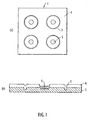
- the sample plate 1 comprises a flat conductive metal plate or substrate 2, preferably stainless steel.
- the substrate 2 is etched, preferably by a laser, so that a number of circular moat portions or grooves 3 are produced in the substrate 2. Each circular moat portion or groove 3 defines a sample position.
- sample positions may be provided on the sample plate 1.
- sample positions For ease of illustration only four sample positions are shown in Fig. 1 , but according to an embodiment 96 sample positions and 24 reference positions may be provided on a 55 mm x 40 mm steel plate.
- the steel plate 2 is approximately 2.5 mm thick.
- the circular moats 3 have a diameter of approximately 2.5 mm and each moat 3 is approximately 0.25 mm wide and 0.25 deep.
- Substrate 2 is coated with a hydrophobic material such as polytetrafluoroethylene ("PTFE") which creates a layer approximately 100 ⁇ m thick or less. As shown in Fig. 1(b) , because of the moat portions 3 there is a dip in the PTFE layer 4 above the corresponding moat 3.
- PTFE polytetrafluoroethylene
- a laser etched region 5 is then made in the centre of each sample portion by laser etching or ablation.
- Each laser etched region 5 has a diameter of approximately 0.4-0.6 mm.
- the precise structure of the laser etched region 5 has not been fully investigated but the steel substrate 2 underneath the upper surface of the laser etched region 5 is roughened or indented by the laser etching process.
- the laser etching process is believed to remove some or all of the PTFE coating leaving behind a roughened region which is presumed to have a large surface area.
- the laser etched region 5 is a roughened region having peaks and troughs.
- the peak to valley height is approximately 30 ⁇ m.
- a thin layer of hydrophobic material preferably polystyrene is applied across at least the roughened laser etched region 5. It may also be applied across substantially the whole of the upper surface of the sample plate 1.
- a sample is preferably deposited in a relatively large volume of 5-10 ⁇ l compared to the sample protocol used with the known sample plate.
- the sample solution preferably contains analyte and a solvent such as 20-30% acetonitrile ("ACN").
- the large volume sample loading of 5-10 ⁇ l is possible because the hydrophobic surface provides an increased contact angle with the sample solution compared to a stainless steel sample plate.
- the sample moat geometry maintains the high contact angle and acts as a barrier to the droplet perimeter.
- the combination of both the hydrophobic surface and the sample moat 3 gives an approximate 5-10 fold improvement in sample volume retention.
- the solvent in the sample solution is allowed to evaporate. During the evaporation the solution droplet is immobilised onto the roughened laser etched regions 5. Bio-molecules preferentially aggregate on the enlarged hydrophobic surfaces due to hydrophobic interactions. Although both PTFE and polystyrene are highly hydrophobic, it is believed that the relatively large surface area of the hydrophobic coating in the micro structure of the roughened laser etched region 5 allows accommodation of a relatively large proportion of the sample over the large surface area of the hydrophobic material within the roughened laser etched regions 5.
- the analyte bio-molecules are immobilised to the enlarged surface area of hydrophobic coating within the laser etched regions 5.
- the sample plate 1 can then be submerged in water to wash the sample and to remove impurities such as inorganic salts.
- the washed sample can then be analysed directly on the sample plate 1 by the addition of a small volume (1 ⁇ l) of matrix.
- the matrix preferably comprises ⁇ -cyano-4-hydroxycinnamic acid (CHCA).
- CHCA ⁇ -cyano-4-hydroxycinnamic acid
- other matrices such as 2,5-dihydroxybenzoic acid (DHB), hydroxypicolinic acid (HPA), 3,5-dimethoxy-4-hydroxycinnamic acid (Sinapinic acid), glycerol, succinic acid, thiourea, 2-(4-hydroxypheylazo)benzoic acid (HABA), esculetin and 2,4,5-trihydroxyacetophenone may be used.
- the matrix solvent preferably has a high organic content typically 70-90%.
- the matrix solvent dissociates the bio-molecules from the roughened laser etched region so allowing the co-crystallisation of analyte and matrix.
- the matrix droplet is also immobilised onto the roughened laser etched region 5 and this ensures that the sample is crystallised in a small area.
- Fig. 2 shows a sample being deposited on to a sample plate and progressively contracting as the solvent evaporates.
- Figs. 3(a)-(c) show three mass spectra of an in solution tryptic digest sample of Alcohol Dehydrogenase (ADH) protein showing the sensitivity and focusing of different concentrations using the sample plate according to the preferred embodiment.
- ADH Alcohol Dehydrogenase
- Each sample volume loaded was 5 ⁇ l.
- the sample concentrations were 2 attomole/ ⁇ l (0.01 fmol),20 attomole/ ⁇ l (0.1 fmol) and 200 attomole/ ⁇ l.
- the detection limit of tryptic peptides using the preferred MALDI sample plate 1 and sample preparation protocols is very low (between 2 and 20 attomole/ ⁇ l),
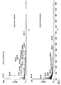
- Figs. 4(a) and (b) shows mass spectra from a 500 fmol digest sample of BSA protein that was injected onto a 1D gel plate (Bio-Rad (RTM)).
- the gel was silver stained and the protein band was cut out and processed using Micromass Massprep (RTM) automated sample preparation station.
- the automated sample processing included destaining of the cut out gel pieces, reduction and alkylation, tryptic digestion, conditioning and spotting onto the MALDI sample plate 1, washing in situ on the MALDI sample plate 1 (to remove salts) and finally addition of matrix onto the MALDI sample plate 1.
- Fig. 4(a) and (b) shows mass spectra from a 500 fmol digest sample of BSA protein that was injected onto a 1D gel plate (Bio-Rad (RTM)).
- the gel was silver stained and the protein band was cut out and processed using Micromass Massprep (RTM) automated sample preparation station.
- the automated sample processing included destaining of the
- FIG. 4(a) shows the resultant mass spectrum where the Massprep loaded 6 ⁇ l (from a total of 20 ⁇ l produced) onto a preferred MALDI sample plate 1 and Fig. 4(b) shows the resultant mass spectrum with a standard loading of 2 ⁇ l onto a conventional MALDI plate.
- the detected intensity of the tryptic peptides is much higher on the preferred MALDI sample plate 1 relative to the standard plate and therefore the ultimate detection limit is significantly lower when using the preferred MALDI sample plate 1.
- Fig. 7 compares mass spectra obtained from using 2 ⁇ l of the same sample used to obtain the mass spectra shown in Figs. 4-6 loaded onto a preferred MALDI sample plate 1 ( Fig. 7(a) ), a standard target plate after Zip Tip sample preparation routine ( Fig. 7(b) ) and a standard stainless steel MALDI sample plate ( Fig. 7(c) ).
- Zip Tips (C18) involve binding of analytes to C18 material followed by washing away of salts and subsequent elution onto a sample plate. It is not a direct in-situ method and suffers from transfer losses. It also does not work well with hydrophobic peptides or high concentrations of salts and CHAPS etc.
- the preferred MALDI sample plate 1 produces significantly higher signals and lower noise levels than the Zip Tip method. In this experiment no significant signal was observed when using a standard MALDI plate ( Fig. 7(c) ).
Landscapes
- Chemical & Material Sciences (AREA)
- Health & Medical Sciences (AREA)
- Analytical Chemistry (AREA)
- Chemical Kinetics & Catalysis (AREA)
- Hematology (AREA)
- Clinical Laboratory Science (AREA)
- General Health & Medical Sciences (AREA)
- Physics & Mathematics (AREA)
- Optics & Photonics (AREA)
- Other Investigation Or Analysis Of Materials By Electrical Means (AREA)
- Sampling And Sample Adjustment (AREA)
- Electron Tubes For Measurement (AREA)
- Prostheses (AREA)
- Cell Separators (AREA)
Claims (36)
- MALDI-Probenplatte, umfassend:ein Substrat (2), umfassend eine Vielzahl von Probenbereichen, die in einem Mikrotiterformat angeordnet sind, wobei jeder Probenbereich (5) Folgendes umfasst:einen lasergeätzten Abschnitt (5), der in dem Substrat (2) gebildet ist, wobei der lasergeätzte Abschnitt (5) ursprünglich hydrophobes Material umfasst, das anschließend durch einen Laser polymerisiert worden ist;einen ersten Abschnitt, der wenigstens einen Teil oder im Wesentlichen das Gesamte des lasergeätzten Abschnitts (5) umgibt;eine Nut (3) oder einen erhöhten Abschnitt, der wenigstens einen Teil oder im Wesentlichen das Gesamte des ersten Abschnitts umgibt;eine erste Schicht (4), die auf wenigstens einem Teil oder im Wesentlichen dem Gesamten des ersten Abschnitts angeordnet ist, wobei die erste Schicht ein erstes hydrophobes Material umfasst, ausgewählt aus der Gruppe bestehend aus: (i) Polytetrafluorethylen ("PTFE") und (ii) Polystyrol; undeine zweite Schicht, die auf wenigstens einem Teil oder im Wesentlichen dem Gesamten des lasergeätzten Abschnitts (5) angeordnet ist, wobei die zweite Schicht ein zweites hydrophobes Material umfasst, ausgewählt aus der Gruppe bestehend aus: (i) Polystyrol und (ii) Polytetrafluorethylen ("PTFE").
- MALDI-Probenplatte gemäß Anspruch 1, wobei die erste Schicht auch auf der Nut (3) oder dem erhöhten Abschnitt angeordnet ist.
- MALDI-Probenplette gemäß Anspruch 1 oder 2, wobei die erste Schicht (4) eine Dicke aufweist, ausgewählt aus der Gruppe bestehend aus: (i) ≤ 5 µm; (ii) 5-10 µm; (iii) 10-15 µm; (iv) 15-20 µm; (v) 20-25 µm; (vi) 25-30 µm; (vii) 30-35 µm; (viii) 35-40 µm; (ix) 40-45 µm; (x) 45-50 µm; (xi) 50-55 µm; (xii) 55-60 µm; (xiii) 60-65 µm; (xiv) 65-70 µm; (xv) 70-75 µm; (xvi) 75-80 µm; (xvii) 80-85 µm; (xviii) 85-90 µm; (xix) 90-95 µm; (xx) 95-100 µm und (xxi) > 100 µm.
- MALDI-Probenplatte gemäß einem der vorstehenden Ansprüche, wobei der Kontaktwinkel eines Lösungsmittel- oder wassertröpfchens mit dem ersten hydrophoben Material (4) ausgewählt ist aus der Gruppe bestehend aus: (i) ≥ 90°; (ii) ≥ 95°; (iii) ≥ 100°; (iv) ≥ 105°; (v) ≥ 110°; (vi) ≥ 115 und (vii) 110-114°.
- MALDI-Probenplatte gemäß einem der vorstehenden Ansprüche, wobei der lasergeätzte Abschnitt (5) einen aufgerauten Bereich des Substrats (2) umfasst.
- MALDI-Probenplatte gemäß einem der vorstehenden Ansprüche, wobei die zweite Schicht auch auf dem ersten Abschnitt angeordnet ist.
- MALDI-Probenplatte gemäß einem der vorstehenden Ansprüche, wobei die zweite Schicht auch auf der Nut (3) oder dem erhöhten Abschnitt angeordnet ist.
- MALDI-Probenplatte gemäß einem der vorstehenden Ansprüche, wobei die zweite Schicht eine Dicke aufweist, ausgewählt aus der Gruppe bestehend aus: (i) ≤ 100 µm; (ii) ≤ 90 µm; (iii) ≤ 80 µm; (iv) ≤ 70 µm; (v) ≤ 60 µm; (V1) ≤ 50 µm; (vii) ≤ 40 µm; (viii) ≤ 30 µm; (ix) ≤ 20 µm; (x) ≤ 10 um; (xi) ≤ 5 µm; (xii) ≤ 1 µm; (xiii) ≤ 100 nm; (xiv) ≤ 10 nm; (xv) ≤ 1 nm; (xvi) 1-5 Monolagen und (xvii) einer einzigen Monolage.
- MALDI-Probenplatte gemäß einem der vorstehenden Ansprüche, wobei der Kontaktwinkel eines Lösungsmittel- oder Wassertröpfchens mit dem zweiten hydrophoben Material ausgewählt ist aus der Gruppe bestehend aus: (i) ≥ 90°; (ii) ≥ 95°; (iii) ≥ 100°; (iv) ≥ 105°; (v) ≥ 110°; (vi) ≥ 115° und (vii) 110-114°.
- MALDI-Probenplatte gemäß einem der vorstehenden Ansprüche, wobei das Substrat (2) ausgewählt ist aus der Gruppe bestehend aus: (i) metallisch; (ii) Kunststoff; (iii) Keramik; (iv) Halbleiter und (v) Glas.
- MALDI-Probenplatte gemäß einem der vorstehenden Ansprüche, wobei die Nut (3) oder der erhöhte Abschnitt im Wesentlichen kreisförmig ist.
- MALDI-Probenplatte gemäß einem der vorstehenden Ansprüche, wobei die Nut (3) oder der erhöhte Abschnitt einen Innendurchmesser aufweist, ausgewählt aus der Gruppe bestehend aus: (i) 2,0-2,2 mm; (ii) 2,2-2,4 mm; (iii) 2,4-2,6 mm; (iv) 2,6-2,8 mm und (v) 2,8-3,0 mm.
- MALDI-Probenplatte gemäß Anspruch 12, wobei die Nut (3) eine Tiefe aufweist oder der erhöhte Abschnitt eine Höhe aufweist, ausgewählt aus der Gruppe bestehend aus: (i) 0,10-0,12; (ii) 0,12-0,14; (iii) 0,14-0,16; (iv) 0,16-0,18; (v) 0,18-0,20; (vi) 0,20-0,22 mm; (vii) 0,22-0,24 mm; (viii) 0,24-0,26 mm; (ix) 0,26-0,28 mm; (x) 0,28-0,30 mm; (xi) 0,30-0,32 mm; (xii) D,32-0,34 mm; (xiii) 0,34-0,36 mm; (xiv) 0,36-0,38 mm; (xv) 0,38-0,40 mm; (xvi) 0,40-0,42 mm; (xvii) 0,42-0,44 mm; (xviii) 0,44-0,46 mm; (xix) 0,46-0,48 mm und (xx) 0,48-0,50 mm.
- MALDI-Probenplatte gemäß Anspruch 12 oder 13, wobei der lasergeätzte Abschnitt (5) einen Durchmesser aufweist, ausgewählt aus der Gruppe bestehend aus: (i) 0,2-0,4 mm; (ii) 0,4-0,6 mm; (iii) 0,6-0,8 mm; (iv) 0,8-1,0 mm; (v) 1,0-1,2 mm; (vi) 1,2-1,4 mm; (vii) 1,4-1,6 mm und (viii) 1,6-1,8 mm.
- MALDI-Probenplatte gemäß einem der Ansprüche 1-11, wobei die Nut (3) oder der erhöhte Abschnitt einen Innendurchmesser aufweist, ausgewählt aus der Gruppe bestehend aus: (i) 1,0-1,2 mm; (ii) 1,2-1,4 mm; (iii) 1,4-1,6 mm; (iv) 1,6-1,8 mm und (v) 1,8-2,0 mm.
- MALDI-Probenplatte gemäß Anspruch 15, wobei die Nut (3) eine Tiefe aufweist oder der erhöhte Abschnitt eine Höhe aufweist, ausgewählt aus der Gruppe bestehend aus: (i) 0,10-0,12; (ii) 0,12-0,14; (iii) 0,14-0,16; (iv) 0,16-0,18; (v) 0,18-0,20; (vi) 0,20-0,22 mm; (vii) 0,22-0,24 mm; (viii) 0,24-0,26 mm; (ix) 0,26-0,28 mm; (x) 0,28-0,30 mm; (xi) 0,30-0,32 mm; (xii) 0,32-0,34 mm; (xiii) 0,34-0,36 mm; (xiv) 0,36-0,38 mm; (xv) 0.38-0, 40 mm; (xvi) 0,40-0,42 mm; (xvii) 0,42-0,44 mm; (xviii) 0,44-0,46 mm; (xix) 0,46-0,48 mm und (xx) 0,48-0,50 mm.
- MALDI-Probenplatte gemäß Anspruch 15 oder 16, wobei der lasergeätzte Abschnitt (5) einen Durchmesser aufweist, ausgewählt aus der Gruppe bestehend aus: (i) 0,2-0,4 mm; (ii) 0,4-0,6 mm; (iii) 0,6-0,8 mm und (iv) 0,8-1,0 mm.
- MALDI-Probenplatte gemäß einem der vorstehenden Ansprüche, wobei der lasergeätzte Abschnitt (5) Höchstpunkte und Tiefstpunkte aufweist, die durch einen mittleren Abstand getrennt sind, ausgewählt aus der Gruppe bestehend aus: (i) 100-90 µm; (ii) 90-80 µm; (iii) 80-70 µm; (iv) 70-60 µm; (v) 60-50 µm; (vi) 50-40 µm; (vii) 40-30 µm; (viii) 30-20 µm; (ix) 20-10 µm und (x) 10-1 µm.
- MALDI-Probenplatte gemäß einem der vorstehenden Ansprüche, wobei der lasergeätzte Abschnitt (5) so angeordnet ist, um eine auf der Probenplatte abgesetzte Probelösung bei Verringern des Volumens einzuziehen.
- MALDI-Probenplatte gemäß einem der vorstehenden Ansprüche, wobei der Rasterabstand zwischen den Proben etwa oder genau 18 mm, 9 mm, 4,5 mm, 2,25 mm oder 1,125 mm beträgt.
- MALDI-Probenplatte gemäß einem der vorstehenden Ansprüche, wobei bis zu 48, 96, 384, 1536 oder 6144 Proben zur Aufnahme auf die Probenplatte angeordnet sind.
- MALDI-Probenplatte gemäß einem der vorstehenden Ansprüche, wobei Proben zum Aufbringen auf die Probenplatte in einem Muster von vier Proben um eine zentrale Kontrollprobenkammer angeordnet sind.
- Kombination einer MALDT-Probenplatte gemäß einem der vorstehenden Ansprüche und auf der Probenplatte aufgebrachter Biomoleküle.
- MALDI-Massenspektrometer in Kombination mit einer MALDI-Probenplatte gemäß einem der Ansprüche 1-22.
- Verfahren der Massenspektrometrie, umfassend den Schritt der Verwendung einer MALDI-Probenplatte gemäß einem der Ansprüche 1-22.
- Verfahren zur Probenvorbereitung, umfassend den folgenden Schritt:automatisches oder manuelles Platzieren von Proben auf eine MALDI-Probenplatte gemäß einem der Ansprüche 1-22.
- Verfahren zur Probenvorbereitung, umfassend den folgenden Schritt:automatisches oder manuelles Waschen von Proben, die auf einer MALDI-Probenplatte gemäß einem der Ansprüche 1-22 aufgebracht sind.
- Verfahren der Massenspektrometrie, umfassend den folgenden Schritt:automatisches oder manuelles Analysieren von Analyt, der auf einer MALDI-Probenplatte gemäß einem der Ansprüche 1-22 aufgebracht ist.
- Verfahren zum Herstellen einer MPLDI-Probenplatte, umfassend die folgenden Schritte:Bereitstellen eines Substrats (2), umfassend eine Vielzahl von Probenbereichen, die in einem Mikrotiterformat angeordnet sind, wobei jeder Probenbereich einen zu laserätzenden Abschnitt und einen ersten Abschnitt, der wenigstens einen Teil oder im Wesentlichen das Gesamte des zu laserätzenden Abschnitts umgibt, umfasst, und wobei eine Nut (3) oder ein erhöhter Abschnitt wenigstens einen Teil oder im Wesentlichen das Gesamte des ersten Abschnitts umgibt;Aufbringen einer ersten Schicht (4) auf wenigstens einem Teil oder im Wesentlichen dem Gesamten des ersten Abschnitts, wobei die erste Schicht ein erstes hydrophobes Material umfasst, ausgewählt aus der Gruppe bestehend aus: (i) Polytetrafluorethylen ("PTFE") und (ii) Polystyrol;Laserätzen der zu laserätzenden Abschnitte jedes Probenbereichs, um so in jedem Probenbereich einen lasergeätzten Abschnitt (5) zu bilden, der ursprünglich hydrophobes Material umfasst, das anschließend durch einen Laser polymerisiert worden ist; undAufbringen einer zweiten Schicht auf wenigstens einem Teil oder im Wesentlichen dem Gesamten des lasergeätzten Abschnitts (5), wobei die zweite Schicht ein zweites hydrophobes Material umfasst, ausgewählt aus der Gruppe bestehend aus: (i) Polystyrol und (ii) Polytetrafluorethylen ("PTFE").
- Verfahren zur Probenvorbereitung, umfassend den folgenden Schritt:automatisches oder manuelles chemisches Entfärben von Gel- oder Membranproben in situ auf einer MALDI-Probenplatte gemäß einem der Ansprüche 1-22.
- Verfahren zur Probenvorbereitung, umfassend den folgenden Schritt:automatisches oder manuelles chemisches Reduzieren von Proben in situ auf einer MALDI-Probenplatte gemäß einem der Ansprüche 1-22.
- Verfahren zur Probenvorbereitung, umfassend den folgenden Schritt:automatisches oder manuelles chemisches Alkylieren von Proben in situ auf einer MALDI-Probenplatte gemäß einem der Ansprüche 1-22.
- verfahren zur Probenvorbereitung, umfassend den folgenden Schritt:automatisches oder manuelles tryptisches oder chemisches Aufschließen von Proben in situ auf einer MALDI-Probenplatte gemäß einem der Ansprüche 1-22.
- Verfahren zur Probenvorbereitung, umfassend den folgenden Schritt:automatisches oder manuelles chemisches Derivatisieren von Proben in situ auf einer MALDI-Probenplatte gemäß einem der Ansprüche 1-22.
- Verfahren zur Probenvorbereitung, umfassend den folgenden Schritt:automatisches oder manuelles Waschen von Proben in situ auf einer MALDI-Probenplatte gemäß einem der ansprüche 1-22, um Gel- oder Membranproben und/oder andere Verunreinigungen zu entfernen.
- Verfahren zur Probenvorbereitung, umfassend wenigstens zwei, drei, vier, fünf oder sechs der folgenden Schritte:(i) automatisches oder manuelles chemisches Entfärben von Gel- oder Membranproben in situ auf einer MALDI-Probenplatte;(ii) automatisches oder manuelles chemisches Reduzieren von Proben in situ auf einer MALDI-Probenplatte;(iii) automatisches oder manuelles chemisches Alkylieren von Proben in situ auf einer MALDI-Probenplatte;(iv) automatisches oder manuelles tryptisches oder chemisches Aufschließen von Proben in situ auf einer MALDI-Probenplatte;(v) automatisches oder manuelles chemisches Derivatisieren von Proben in situ auf einer MALDI-Probenplatte und(vi) automatisches oder manuelles waschen von Proben in situ auf einer MALDI-Probenplatte, um Gel- oder Membranproben und/oder andere Verunreinigungen zu entfernen,wobei die MALDI-Probenplatte eine MALDI-Probenplette gemäß einem der Ansprüche 1-22 ist.
Applications Claiming Priority (2)
| Application Number | Priority Date | Filing Date | Title |
|---|---|---|---|
| GB0120131 | 2001-08-17 | ||
| GBGB0120131.8A GB0120131D0 (en) | 2001-08-17 | 2001-08-17 | Maldi target plate |
Publications (3)
| Publication Number | Publication Date |
|---|---|
| EP1284495A2 EP1284495A2 (de) | 2003-02-19 |
| EP1284495A3 EP1284495A3 (de) | 2005-12-28 |
| EP1284495B1 true EP1284495B1 (de) | 2012-05-02 |
Family
ID=9920606
Family Applications (1)
| Application Number | Title | Priority Date | Filing Date |
|---|---|---|---|
| EP02255756A Expired - Lifetime EP1284495B1 (de) | 2001-08-17 | 2002-08-19 | Massenspektrometer |
Country Status (5)
| Country | Link |
|---|---|
| US (2) | US6952011B2 (de) |
| EP (1) | EP1284495B1 (de) |
| AT (1) | ATE555852T1 (de) |
| CA (1) | CA2398680C (de) |
| GB (2) | GB0120131D0 (de) |
Families Citing this family (70)
| Publication number | Priority date | Publication date | Assignee | Title |
|---|---|---|---|---|
| EP1401558A4 (de) | 2001-05-25 | 2007-12-12 | Waters Investments Ltd | Entsalzungsplatte für maldi-massenspektroskopie |
| WO2004072616A2 (en) * | 2003-02-10 | 2004-08-26 | Waters Investments Limited | A sample preparation plate for mass spectrometry |
| EP1478925A1 (de) * | 2002-02-22 | 2004-11-24 | Sunyx Surface Nanotechnologies GmbH | Verwendung von ultraphoben oberflächen mit einer vielzahl hydrophiler bereiche zur analyse von proben |
| JP4052094B2 (ja) * | 2002-11-11 | 2008-02-27 | 株式会社島津製作所 | レーザー脱離イオン化質量分析における試料作成方法とそれに用いるサンプルプレート |
| US20040185448A1 (en) * | 2003-03-20 | 2004-09-23 | Viorica Lopez-Avila | Methods and devices for performing matrix assisted laser desorption/lonization protocols |
| US6891156B2 (en) * | 2003-04-30 | 2005-05-10 | Perkin Elmer Instruments Llc | Sample plate for matrix-assisted laser desorption and ionization mass spectrometry |
| US7858387B2 (en) | 2003-04-30 | 2010-12-28 | Perkinelmer Health Sciences, Inc. | Method of scanning a sample plate surface mask in an area adjacent to a conductive area using matrix-assisted laser desorption and ionization mass spectrometry |
| DE602004010949T3 (de) * | 2003-05-13 | 2011-09-15 | Hitachi, Ltd. | Einrichtung zur Bestrahlung mit Teilchenstrahlen und Bestrahlungsplanungseinheit |
| CA2467131C (en) * | 2003-05-13 | 2013-12-10 | Becton, Dickinson & Company | Method and apparatus for processing biological and chemical samples |
| US6963066B2 (en) | 2003-06-05 | 2005-11-08 | Thermo Finnigan Llc | Rod assembly in ion source |
| GB0313170D0 (en) | 2003-06-09 | 2003-07-16 | Qinetiq Ltd | Method and apparatus for spore disruption and/or detection |
| FR2857451B1 (fr) | 2003-07-11 | 2005-09-30 | Commissariat Energie Atomique | Procede et dispositif pour l'analyse de milieux reactionnels vivants |
| US20050164402A1 (en) * | 2003-07-14 | 2005-07-28 | Belisle Christopher M. | Sample presentation device |
| US7833745B2 (en) * | 2003-09-11 | 2010-11-16 | E. I. Du Pont De Nemours And Company | Direct detection method for products of cellular metabolism using ToF-SIMS |
| EP1676292A4 (de) * | 2003-10-10 | 2009-01-07 | Protein Discovery Inc | Verfahren und einrichtungen zum konzentrieren und reinigen von analyten für die chemische analyse unter verwendung der matrixunterstützten laserdesorptions-/-ionisations-(maldi-)massenspektrometrie (ms) |
| US6844545B1 (en) * | 2003-10-10 | 2005-01-18 | Perseptive Biosystems, Inc. | MALDI plate with removable insert |
| US20090215192A1 (en) * | 2004-05-27 | 2009-08-27 | Stratos Biosystems, Llc | Solid-phase affinity-based method for preparing and manipulating an analyte-containing solution |
| JP4441336B2 (ja) * | 2004-06-11 | 2010-03-31 | 日本碍子株式会社 | マイクロアレイの製造方法 |
| DE102004058555A1 (de) * | 2004-12-03 | 2006-06-08 | Qiagen Gmbh | Verfahren zur Aufkonzentrierung von Biomolekülen in der Nähe der Oberfläche einer kristallinen Struktur |
| KR100544860B1 (ko) * | 2005-02-07 | 2006-01-24 | (주)프로테오니크 | 시료 플레이트 및 이의 제조방법 |
| US7619215B2 (en) * | 2005-02-07 | 2009-11-17 | Yangsun Kim | Sample plate for MALDI mass spectrometry and process for manufacture of the same |
| US7262841B2 (en) * | 2005-03-17 | 2007-08-28 | Agilent Technologies, Inc. | Laser alignment for ion source |
| US20060266941A1 (en) * | 2005-05-26 | 2006-11-30 | Vestal Marvin L | Method and apparatus for interfacing separations techniques to MALDI-TOF mass spectrometry |
| US20070258864A1 (en) * | 2005-12-08 | 2007-11-08 | Protein Discovery, Inc. | Methods and devices for concentration and fractionation of analytes for chemical analysis |
| US7687772B2 (en) * | 2006-01-27 | 2010-03-30 | National Sun Yat-Sen University | Mass spectrometric imaging method under ambient conditions using electrospray-assisted laser desorption ionization mass spectrometry |
| US7465921B1 (en) * | 2006-03-02 | 2008-12-16 | Agilent Technologies, Inc. | Structured carbon nanotube tray for MALDI plates |
| WO2007133714A2 (en) * | 2006-05-12 | 2007-11-22 | Stratos Biosystems, Llc | Analyte focusing biochips for affinity mass spectrometry |
| US20080116366A1 (en) * | 2006-11-17 | 2008-05-22 | Jantaie Shiea | Laser desorption device, mass spectrometer assembly, and method for ambient liquid mass spectrometry |
| US7589319B2 (en) | 2007-05-01 | 2009-09-15 | Virgin Instruments Corporation | Reflector TOF with high resolution and mass accuracy for peptides and small molecules |
| US7564028B2 (en) * | 2007-05-01 | 2009-07-21 | Virgin Instruments Corporation | Vacuum housing system for MALDI-TOF mass spectrometry |
| US7663100B2 (en) * | 2007-05-01 | 2010-02-16 | Virgin Instruments Corporation | Reversed geometry MALDI TOF |
| US7667195B2 (en) * | 2007-05-01 | 2010-02-23 | Virgin Instruments Corporation | High performance low cost MALDI MS-MS |
| US7564026B2 (en) * | 2007-05-01 | 2009-07-21 | Virgin Instruments Corporation | Linear TOF geometry for high sensitivity at high mass |
| US7838824B2 (en) * | 2007-05-01 | 2010-11-23 | Virgin Instruments Corporation | TOF-TOF with high resolution precursor selection and multiplexed MS-MS |
| GB0712795D0 (en) * | 2007-07-02 | 2007-08-08 | Ecole Polytechnique Federale De | Solid phase extraction and ionization device |
| WO2013114217A1 (en) * | 2012-02-05 | 2013-08-08 | Curiox Biosystems Pte Ltd. | Array plates and methods for making and using same |
| US7888127B2 (en) | 2008-01-15 | 2011-02-15 | Sequenom, Inc. | Methods for reducing adduct formation for mass spectrometry analysis |
| US8598511B1 (en) | 2008-03-05 | 2013-12-03 | University Of South Florida | Carbon nanotube anchor for mass spectrometer |
| JP5072682B2 (ja) * | 2008-03-28 | 2012-11-14 | 富士フイルム株式会社 | 質量分析用デバイス、これを用いる質量分析装置および質量分析方法 |
| EP2106858B1 (de) * | 2008-03-31 | 2011-11-02 | Sony DADC Austria AG | Substrat und Zielplatte |
| WO2009134120A1 (en) * | 2008-04-29 | 2009-11-05 | Erasmus University Medical Center Rotterdam | Mass spectrometric analysis of small molecule analytes |
| US9455130B2 (en) * | 2008-07-30 | 2016-09-27 | The Brigham And Women's Hospital, Inc. | Preparation of test plates for matrix assisted laser desorption ionization |
| CN102439398A (zh) * | 2009-04-27 | 2012-05-02 | 蛋白质发现公司 | 可编程电泳凹口过滤器系统及方法 |
| WO2011097677A1 (en) * | 2010-02-12 | 2011-08-18 | Monash University | Printed multi-zone microzone plates |
| US9211542B2 (en) | 2010-05-21 | 2015-12-15 | Eidgenossische Technische Hochschule Zurich | High-density sample support plate for automated sample aliquoting |
| US9305756B2 (en) * | 2013-03-13 | 2016-04-05 | Agena Bioscience, Inc. | Preparation enhancements and methods of use for MALDI mass spectrometry |
| US9799501B2 (en) * | 2013-08-07 | 2017-10-24 | Citizen Finedevice Co., Ltd. | Sample mounting plate |
| JP6111941B2 (ja) * | 2013-09-06 | 2017-04-12 | 日本軽金属株式会社 | バイオチップ用基板 |
| JP6591160B2 (ja) * | 2014-12-25 | 2019-10-16 | シチズンファインデバイス株式会社 | 試料積載プレート |
| US10978284B2 (en) | 2015-03-06 | 2021-04-13 | Micromass Uk Limited | Imaging guided ambient ionisation mass spectrometry |
| GB2556994B (en) | 2015-03-06 | 2021-05-12 | Micromass Ltd | Identification of bacterial strains in biological samples using mass spectrometry |
| GB2553941B (en) | 2015-03-06 | 2021-02-17 | Micromass Ltd | Chemically guided ambient ionisation mass spectrometry |
| CN107580675B (zh) | 2015-03-06 | 2020-12-08 | 英国质谱公司 | 拭子和活检样品的快速蒸发电离质谱(“reims”)和解吸电喷雾电离质谱(“desi-ms”)分析 |
| EP3726562B1 (de) | 2015-03-06 | 2023-12-20 | Micromass UK Limited | Bildgebungsplattform für umgebungsionisierungsmassenspektrometrie für direkte abbildung aus gesamtgewebe |
| WO2016142681A1 (en) | 2015-03-06 | 2016-09-15 | Micromass Uk Limited | Spectrometric analysis of microbes |
| CN107530065A (zh) | 2015-03-06 | 2018-01-02 | 英国质谱公司 | 活体内内窥镜下组织识别工具 |
| WO2016142686A1 (en) | 2015-03-06 | 2016-09-15 | Micromass Uk Limited | Liquid trap or separator for electrosurgical applications |
| WO2016142692A1 (en) | 2015-03-06 | 2016-09-15 | Micromass Uk Limited | Spectrometric analysis |
| CN107530064B (zh) | 2015-03-06 | 2021-07-30 | 英国质谱公司 | 气态样品的改进电离 |
| JP6800875B2 (ja) | 2015-03-06 | 2020-12-16 | マイクロマス ユーケー リミテッド | 急速蒸発イオン化質量分析(「reims」)装置に連結されたイオンアナライザのための流入器具 |
| CN108700590B (zh) | 2015-03-06 | 2021-03-02 | 英国质谱公司 | 细胞群体分析 |
| GB2552430B (en) | 2015-03-06 | 2022-05-11 | Micromass Ltd | Collision surface for improved ionisation |
| US11037774B2 (en) * | 2015-03-06 | 2021-06-15 | Micromass Uk Limited | Physically guided rapid evaporative ionisation mass spectrometry (“REIMS”) |
| GB201517195D0 (en) | 2015-09-29 | 2015-11-11 | Micromass Ltd | Capacitively coupled reims technique and optically transparent counter electrode |
| WO2017159879A1 (ja) | 2016-03-18 | 2017-09-21 | シチズンファインデバイス株式会社 | 試料積載プレート及びその製造方法 |
| EP3443354B1 (de) | 2016-04-14 | 2025-08-20 | Micromass UK Limited | Spektrometrische analyse von pflanzen |
| GB201705981D0 (en) * | 2017-04-13 | 2017-05-31 | Micromass Ltd | MALDI target plate |
| JP7496300B2 (ja) * | 2020-12-14 | 2024-06-06 | 浜松ホトニクス株式会社 | 試料支持体、イオン化法及び質量分析方法 |
| GB2605958A (en) * | 2021-04-15 | 2022-10-26 | Micromass Ltd | Ion source sample plate |
| CN118443404B (zh) * | 2024-05-07 | 2024-11-29 | 康丽达精密科技(苏州)有限公司 | 一种质谱检测用样品靶板的制备方法 |
Family Cites Families (36)
| Publication number | Priority date | Publication date | Assignee | Title |
|---|---|---|---|---|
| US68133A (en) * | 1867-08-27 | Richabd vose | ||
| US10908A (en) * | 1854-05-16 | Table fob ships cabin s | ||
| US150903A (en) * | 1874-05-12 | Improvement in feathering paddle-wheels | ||
| US51738A (en) * | 1865-12-26 | Improvement in horseshoes | ||
| US121595A (en) * | 1871-12-05 | Improvement in the manufacture of bleaching-powders, sulphates | ||
| US57368A (en) * | 1866-08-21 | Stove-pipe damper | ||
| US626575A (en) * | 1899-06-06 | Eyeglass-gage | ||
| US4405692A (en) * | 1981-12-04 | 1983-09-20 | Hughes Aircraft Company | Moisture-protected alkali halide infrared windows |
| GB2257295B (en) * | 1991-06-21 | 1994-11-16 | Finnigan Mat Ltd | Sample holder for use in a mass spectrometer |
| US5605798A (en) | 1993-01-07 | 1997-02-25 | Sequenom, Inc. | DNA diagnostic based on mass spectrometry |
| CA2512290C (en) | 1993-05-28 | 2010-02-02 | Baylor College Of Medicine | Method and apparatus for desorption and ionization of analytes |
| US6071610A (en) | 1993-11-12 | 2000-06-06 | Waters Investments Limited | Enhanced resolution matrix-laser desorption and ionization TOF-MS sample surface |
| US6004770A (en) | 1995-06-07 | 1999-12-21 | Arizona State University Board Of Regents | Sample presentation apparatus for mass spectrometry |
| DE19617011C2 (de) | 1996-04-27 | 2000-11-02 | Bruker Daltonik Gmbh | Matrixkomponentengemisch für die matrixunterstützte Laserdesorption und Ionisierung sowie Verfahren zur Zubereitung eines Matrixkomponentengemisches |
| DE19618032C2 (de) | 1996-05-04 | 2000-04-13 | Bruker Daltonik Gmbh | Lagerfähig vorpräparierte Maldi-Probenträger |
| NZ516848A (en) | 1997-06-20 | 2004-03-26 | Ciphergen Biosystems Inc | Retentate chromatography apparatus with applications in biology and medicine |
| DE69824586T2 (de) * | 1997-06-26 | 2005-06-23 | PerSeptive Biosystems, Inc., Framingham | Probenträger hoher dichte für die analyse biologischer proben |
| DE19754978C2 (de) | 1997-12-11 | 2000-07-13 | Bruker Daltonik Gmbh | Probenträger für die MALDI-Massenspektrometrie nebst Verfahren zur Herstellung der Platten und zum Aufbringen der Proben |
| EP1051259B1 (de) | 1998-01-12 | 2006-04-05 | Massachusetts Institute Of Technology | Verfahren und vorrichtung zur mikrotestdurchführung |
| US6893877B2 (en) | 1998-01-12 | 2005-05-17 | Massachusetts Institute Of Technology | Methods for screening substances in a microwell array |
| US6265715B1 (en) | 1998-02-02 | 2001-07-24 | Helene Perreault | Non-porous membrane for MALDI-TOFMS |
| KR100713786B1 (ko) | 1999-04-27 | 2007-05-07 | 바이오 래드 래버러토리스 인코오포레이티드 | 기체상 이온 분광계용 탐침 |
| KR20020022653A (ko) * | 1999-04-29 | 2002-03-27 | 사이퍼젠 바이오시스템스, 인코오포레이티드 | 기체상 질량 분광계용 소수성 코팅을 구비한 샘플 홀더 |
| WO2000077812A2 (en) | 1999-06-10 | 2000-12-21 | Northeastern University | Light-induced electron capture at a surface |
| JP3548769B2 (ja) | 1999-06-29 | 2004-07-28 | 旭テクネイオン株式会社 | 微細で均一な結晶を形成するためのカーボン製支持板及びその応用 |
| WO2001019520A1 (en) | 1999-09-13 | 2001-03-22 | Millipore Corporation | High density cast-in-place sample preparation card |
| JP2004502276A (ja) | 2000-06-28 | 2004-01-22 | ザ ジョンズ ホプキンズ ユニバーシティ | 飛行時間型質量分析計配列装置 |
| DE10043042C2 (de) | 2000-09-01 | 2003-04-17 | Bruker Daltonik Gmbh | Verfahren zum Belegen eines Probenträgers mit Biomolekülen für die massenspektrometrische Analyse |
| US6539102B1 (en) * | 2000-09-01 | 2003-03-25 | Large Scale Proteomics | Reference database |
| EP1330306A2 (de) * | 2000-10-10 | 2003-07-30 | BioTrove, Inc. | Vorrichtung zum testen, synthese und lagerung sowie verfahren zur herstellung, verwendung und handhabung |
| US6825477B2 (en) | 2001-02-28 | 2004-11-30 | Jan Sunner | Method and apparatus to produce gas phase analyte ions |
| EP1395824A1 (de) | 2001-05-14 | 2004-03-10 | The Penn State Research Foundation | Matrixfreie desorptionsionisierungsmassenspektrometrie unter verwendung angepasster morphologieschichteinrichtungen |
| WO2002097392A2 (en) | 2001-05-25 | 2002-12-05 | Waters Investments Limited | Sample concentration maldi plates for maldi mass spectrometry |
| US20030010908A1 (en) | 2001-07-02 | 2003-01-16 | Phillip Clark | Conductive card suitable as a MALDI-TOF target |
| DE10140499B4 (de) | 2001-08-17 | 2005-02-03 | Bruker Daltonik Gmbh | Probenträgerplatten für Massenspektrometrie mit Ionisierung durch matrixunterstützte Laserdesorption |
| US20040058059A1 (en) * | 2001-11-07 | 2004-03-25 | Linford Mathew Richard | Funtionalized patterned surfaces |
-
2001
- 2001-08-17 GB GBGB0120131.8A patent/GB0120131D0/en not_active Ceased
-
2002
- 2002-08-16 CA CA2398680A patent/CA2398680C/en not_active Expired - Lifetime
- 2002-08-19 GB GB0219309A patent/GB2381068B/en not_active Expired - Fee Related
- 2002-08-19 AT AT02255756T patent/ATE555852T1/de active
- 2002-08-19 US US10/223,401 patent/US6952011B2/en not_active Expired - Lifetime
- 2002-08-19 EP EP02255756A patent/EP1284495B1/de not_active Expired - Lifetime
-
2005
- 2005-08-03 US US11/196,820 patent/US7294831B2/en not_active Expired - Fee Related
Also Published As
| Publication number | Publication date |
|---|---|
| US6952011B2 (en) | 2005-10-04 |
| EP1284495A3 (de) | 2005-12-28 |
| US7294831B2 (en) | 2007-11-13 |
| GB0120131D0 (en) | 2001-10-10 |
| US20030116707A1 (en) | 2003-06-26 |
| EP1284495A2 (de) | 2003-02-19 |
| US20050274885A1 (en) | 2005-12-15 |
| GB2381068C (en) | 2003-09-10 |
| GB0219309D0 (en) | 2002-09-25 |
| ATE555852T1 (de) | 2012-05-15 |
| GB2381068A (en) | 2003-04-23 |
| CA2398680A1 (en) | 2003-02-17 |
| GB2381068B (en) | 2003-09-10 |
| CA2398680C (en) | 2010-10-26 |
Similar Documents
| Publication | Publication Date | Title |
|---|---|---|
| EP1284495B1 (de) | Massenspektrometer | |
| US5595636A (en) | Method for mass spectrometric analysis of samples from electrophoresis plates | |
| US7361311B2 (en) | System and method for the preparation of arrays of biological or other molecules | |
| Foret et al. | Liquid phase interfacing and miniaturization in matrix‐assisted laser desorption/ionization mass spectrometry | |
| US20030138823A1 (en) | Sample preparation methods for maldi mass spectrometry | |
| Kussmann et al. | Sample preparation techniques for peptides and proteins analyzed by MALDI-MS | |
| US9211542B2 (en) | High-density sample support plate for automated sample aliquoting | |
| Kruse et al. | Direct assay of Aplysia tissues and cells with laser desorption/ionization mass spectrometry on porous silicon | |
| US20050040328A1 (en) | Reduction of matrix interference for MALDI mass spectrometry analysis | |
| US20060016984A1 (en) | Sample preparation plate for mass spectrometry | |
| US20050031496A1 (en) | Target plate for mass spectometers and use thereof | |
| US20110095201A1 (en) | Electrowetting sample presentation device for matrix-assisted laser desorption/ionization mass spectrometry and related methods | |
| US20100148052A1 (en) | Analytical carrier and application thereof | |
| Shen et al. | Preparation and characterization of nitrilotriacetic-acid-terminated self-assembled monolayers on gold surfaces for matrix-assisted laser desorption ionization-time of flight-mass spectrometry analysis of proteins and peptides | |
| Hua et al. | Novel polymer composite to eliminate background matrix ions in matrix assisted laser desorption/ionization-mass spectrometry | |
| WO2006083151A1 (en) | Sample plate for maldi mass spectrometry and process for manufacture of the same | |
| JP2007309668A (ja) | レーザー脱離イオン化質量分析用サンプルプレート | |
| Afonso et al. | Activated surfaces for laser desorption mass spectrometry: application for peptide and protein analysis | |
| JP4432411B2 (ja) | レーザー脱離イオン化質量分析法 | |
| Dias | A microdevice for the improved presentation of biological samples for MALDI-TOF mass spectrometry | |
| Jespersen et al. | Picoliter Vials: A New Sample Handling Technique for Matrix-Assisted Laser Desorption/Ionization Mass Spectrometry | |
| Zubarev et al. | By CONNIE R. JIMÉNEZ | |
| Wen | Small molecule matrix-free laser desorption/ionization mass spectrometry |
Legal Events
| Date | Code | Title | Description |
|---|---|---|---|
| PUAI | Public reference made under article 153(3) epc to a published international application that has entered the european phase |
Free format text: ORIGINAL CODE: 0009012 |
|
| AK | Designated contracting states |
Designated state(s): AT BE BG CH CY CZ DE DK EE ES FI FR GB GR IE IT LI LU MC NL PT SE SK TR |
|
| AX | Request for extension of the european patent |
Extension state: AL LT LV MK RO SI |
|
| RAP1 | Party data changed (applicant data changed or rights of an application transferred) |
Owner name: MICROMASS UK LIMITED |
|
| PUAL | Search report despatched |
Free format text: ORIGINAL CODE: 0009013 |
|
| AK | Designated contracting states |
Kind code of ref document: A3 Designated state(s): AT BE BG CH CY CZ DE DK EE ES FI FR GB GR IE IT LI LU MC NL PT SE SK TR |
|
| AX | Request for extension of the european patent |
Extension state: AL LT LV MK RO SI |
|
| 17P | Request for examination filed |
Effective date: 20060626 |
|
| AKX | Designation fees paid |
Designated state(s): AT BE BG CH CY CZ DE DK EE ES FI FR GB GR IE IT LI LU MC NL PT SE SK TR |
|
| RIC1 | Information provided on ipc code assigned before grant |
Ipc: H01J 49/04 20060101ALI20101220BHEP Ipc: H01J 49/16 20060101AFI20101220BHEP |
|
| REG | Reference to a national code |
Ref country code: DE Ref legal event code: R079 Ref document number: 60242792 Country of ref document: DE Free format text: PREVIOUS MAIN CLASS: H01J0049400000 Ipc: B01L0003000000 |
|
| GRAP | Despatch of communication of intention to grant a patent |
Free format text: ORIGINAL CODE: EPIDOSNIGR1 |
|
| RIC1 | Information provided on ipc code assigned before grant |
Ipc: B01L 3/00 20060101AFI20120105BHEP Ipc: H01J 49/04 20060101ALI20120105BHEP |
|
| RBV | Designated contracting states (corrected) |
Designated state(s): AT BE BG CH CY CZ DE DK EE ES FI FR GR IE IT LI LU MC NL PT SE SK TR |
|
| GRAS | Grant fee paid |
Free format text: ORIGINAL CODE: EPIDOSNIGR3 |
|
| GRAA | (expected) grant |
Free format text: ORIGINAL CODE: 0009210 |
|
| AK | Designated contracting states |
Kind code of ref document: B1 Designated state(s): AT BE BG CH CY CZ DE DK EE ES FI FR GR IE IT LI LU MC NL PT SE SK TR |
|
| REG | Reference to a national code |
Ref country code: CH Ref legal event code: EP Ref country code: AT Ref legal event code: REF Ref document number: 555852 Country of ref document: AT Kind code of ref document: T Effective date: 20120515 |
|
| REG | Reference to a national code |
Ref country code: IE Ref legal event code: FG4D |
|
| REG | Reference to a national code |
Ref country code: DE Ref legal event code: R096 Ref document number: 60242792 Country of ref document: DE Effective date: 20120705 |
|
| REG | Reference to a national code |
Ref country code: NL Ref legal event code: VDEP Effective date: 20120502 |
|
| PG25 | Lapsed in a contracting state [announced via postgrant information from national office to epo] |
Ref country code: CY Free format text: LAPSE BECAUSE OF FAILURE TO SUBMIT A TRANSLATION OF THE DESCRIPTION OR TO PAY THE FEE WITHIN THE PRESCRIBED TIME-LIMIT Effective date: 20120502 Ref country code: SE Free format text: LAPSE BECAUSE OF FAILURE TO SUBMIT A TRANSLATION OF THE DESCRIPTION OR TO PAY THE FEE WITHIN THE PRESCRIBED TIME-LIMIT Effective date: 20120502 Ref country code: FI Free format text: LAPSE BECAUSE OF FAILURE TO SUBMIT A TRANSLATION OF THE DESCRIPTION OR TO PAY THE FEE WITHIN THE PRESCRIBED TIME-LIMIT Effective date: 20120502 |
|
| REG | Reference to a national code |
Ref country code: AT Ref legal event code: MK05 Ref document number: 555852 Country of ref document: AT Kind code of ref document: T Effective date: 20120502 |
|
| PG25 | Lapsed in a contracting state [announced via postgrant information from national office to epo] |
Ref country code: PT Free format text: LAPSE BECAUSE OF FAILURE TO SUBMIT A TRANSLATION OF THE DESCRIPTION OR TO PAY THE FEE WITHIN THE PRESCRIBED TIME-LIMIT Effective date: 20120903 Ref country code: GR Free format text: LAPSE BECAUSE OF FAILURE TO SUBMIT A TRANSLATION OF THE DESCRIPTION OR TO PAY THE FEE WITHIN THE PRESCRIBED TIME-LIMIT Effective date: 20120803 |
|
| PG25 | Lapsed in a contracting state [announced via postgrant information from national office to epo] |
Ref country code: BE Free format text: LAPSE BECAUSE OF FAILURE TO SUBMIT A TRANSLATION OF THE DESCRIPTION OR TO PAY THE FEE WITHIN THE PRESCRIBED TIME-LIMIT Effective date: 20120502 |
|
| PG25 | Lapsed in a contracting state [announced via postgrant information from national office to epo] |
Ref country code: CZ Free format text: LAPSE BECAUSE OF FAILURE TO SUBMIT A TRANSLATION OF THE DESCRIPTION OR TO PAY THE FEE WITHIN THE PRESCRIBED TIME-LIMIT Effective date: 20120502 Ref country code: NL Free format text: LAPSE BECAUSE OF FAILURE TO SUBMIT A TRANSLATION OF THE DESCRIPTION OR TO PAY THE FEE WITHIN THE PRESCRIBED TIME-LIMIT Effective date: 20120502 Ref country code: EE Free format text: LAPSE BECAUSE OF FAILURE TO SUBMIT A TRANSLATION OF THE DESCRIPTION OR TO PAY THE FEE WITHIN THE PRESCRIBED TIME-LIMIT Effective date: 20120502 Ref country code: AT Free format text: LAPSE BECAUSE OF FAILURE TO SUBMIT A TRANSLATION OF THE DESCRIPTION OR TO PAY THE FEE WITHIN THE PRESCRIBED TIME-LIMIT Effective date: 20120502 Ref country code: DK Free format text: LAPSE BECAUSE OF FAILURE TO SUBMIT A TRANSLATION OF THE DESCRIPTION OR TO PAY THE FEE WITHIN THE PRESCRIBED TIME-LIMIT Effective date: 20120502 Ref country code: SK Free format text: LAPSE BECAUSE OF FAILURE TO SUBMIT A TRANSLATION OF THE DESCRIPTION OR TO PAY THE FEE WITHIN THE PRESCRIBED TIME-LIMIT Effective date: 20120502 |
|
| PG25 | Lapsed in a contracting state [announced via postgrant information from national office to epo] |
Ref country code: IT Free format text: LAPSE BECAUSE OF FAILURE TO SUBMIT A TRANSLATION OF THE DESCRIPTION OR TO PAY THE FEE WITHIN THE PRESCRIBED TIME-LIMIT Effective date: 20120502 |
|
| PLBE | No opposition filed within time limit |
Free format text: ORIGINAL CODE: 0009261 |
|
| STAA | Information on the status of an ep patent application or granted ep patent |
Free format text: STATUS: NO OPPOSITION FILED WITHIN TIME LIMIT |
|
| REG | Reference to a national code |
Ref country code: CH Ref legal event code: PL |
|
| PG25 | Lapsed in a contracting state [announced via postgrant information from national office to epo] |
Ref country code: MC Free format text: LAPSE BECAUSE OF NON-PAYMENT OF DUE FEES Effective date: 20120831 |
|
| 26N | No opposition filed |
Effective date: 20130205 |
|
| PG25 | Lapsed in a contracting state [announced via postgrant information from national office to epo] |
Ref country code: LI Free format text: LAPSE BECAUSE OF NON-PAYMENT OF DUE FEES Effective date: 20120831 Ref country code: CH Free format text: LAPSE BECAUSE OF NON-PAYMENT OF DUE FEES Effective date: 20120831 Ref country code: ES Free format text: LAPSE BECAUSE OF FAILURE TO SUBMIT A TRANSLATION OF THE DESCRIPTION OR TO PAY THE FEE WITHIN THE PRESCRIBED TIME-LIMIT Effective date: 20120813 |
|
| REG | Reference to a national code |
Ref country code: IE Ref legal event code: MM4A |
|
| REG | Reference to a national code |
Ref country code: DE Ref legal event code: R097 Ref document number: 60242792 Country of ref document: DE Effective date: 20130205 |
|
| PG25 | Lapsed in a contracting state [announced via postgrant information from national office to epo] |
Ref country code: BG Free format text: LAPSE BECAUSE OF FAILURE TO SUBMIT A TRANSLATION OF THE DESCRIPTION OR TO PAY THE FEE WITHIN THE PRESCRIBED TIME-LIMIT Effective date: 20120802 Ref country code: IE Free format text: LAPSE BECAUSE OF NON-PAYMENT OF DUE FEES Effective date: 20120819 |
|
| PG25 | Lapsed in a contracting state [announced via postgrant information from national office to epo] |
Ref country code: TR Free format text: LAPSE BECAUSE OF FAILURE TO SUBMIT A TRANSLATION OF THE DESCRIPTION OR TO PAY THE FEE WITHIN THE PRESCRIBED TIME-LIMIT Effective date: 20120502 |
|
| PG25 | Lapsed in a contracting state [announced via postgrant information from national office to epo] |
Ref country code: LU Free format text: LAPSE BECAUSE OF NON-PAYMENT OF DUE FEES Effective date: 20120819 |
|
| REG | Reference to a national code |
Ref country code: FR Ref legal event code: PLFP Year of fee payment: 15 |
|
| REG | Reference to a national code |
Ref country code: FR Ref legal event code: PLFP Year of fee payment: 16 |
|
| PGFP | Annual fee paid to national office [announced via postgrant information from national office to epo] |
Ref country code: FR Payment date: 20170825 Year of fee payment: 16 |
|
| PGFP | Annual fee paid to national office [announced via postgrant information from national office to epo] |
Ref country code: DE Payment date: 20180719 Year of fee payment: 17 |
|
| PG25 | Lapsed in a contracting state [announced via postgrant information from national office to epo] |
Ref country code: FR Free format text: LAPSE BECAUSE OF NON-PAYMENT OF DUE FEES Effective date: 20180831 |
|
| REG | Reference to a national code |
Ref country code: DE Ref legal event code: R119 Ref document number: 60242792 Country of ref document: DE |
|
| PG25 | Lapsed in a contracting state [announced via postgrant information from national office to epo] |
Ref country code: DE Free format text: LAPSE BECAUSE OF NON-PAYMENT OF DUE FEES Effective date: 20200303 |