EP1284003B1 - Magnetspulenanordnung - Google Patents
Magnetspulenanordnung Download PDFInfo
- Publication number
- EP1284003B1 EP1284003B1 EP01931659A EP01931659A EP1284003B1 EP 1284003 B1 EP1284003 B1 EP 1284003B1 EP 01931659 A EP01931659 A EP 01931659A EP 01931659 A EP01931659 A EP 01931659A EP 1284003 B1 EP1284003 B1 EP 1284003B1
- Authority
- EP
- European Patent Office
- Prior art keywords
- coil arrangement
- connecting part
- plug
- metal housing
- fact
- Prior art date
- Legal status (The legal status is an assumption and is not a legal conclusion. Google has not performed a legal analysis and makes no representation as to the accuracy of the status listed.)
- Expired - Lifetime
Links
- 238000007789 sealing Methods 0.000 claims abstract description 57
- 239000002184 metal Substances 0.000 claims abstract description 50
- 230000001681 protective effect Effects 0.000 claims description 13
- 239000004020 conductor Substances 0.000 claims description 12
- 238000005516 engineering process Methods 0.000 abstract 1
- 239000012530 fluid Substances 0.000 abstract 1
- 238000005538 encapsulation Methods 0.000 description 12
- 238000004804 winding Methods 0.000 description 6
- 230000000694 effects Effects 0.000 description 5
- 238000004519 manufacturing process Methods 0.000 description 4
- 238000002844 melting Methods 0.000 description 3
- 230000008018 melting Effects 0.000 description 3
- 230000000712 assembly Effects 0.000 description 2
- 238000000429 assembly Methods 0.000 description 2
- 238000001816 cooling Methods 0.000 description 2
- 238000007765 extrusion coating Methods 0.000 description 2
- 239000000463 material Substances 0.000 description 2
- 230000008646 thermal stress Effects 0.000 description 2
- 230000005540 biological transmission Effects 0.000 description 1
- 238000005352 clarification Methods 0.000 description 1
- 150000001875 compounds Chemical class 0.000 description 1
- 238000011161 development Methods 0.000 description 1
- 230000018109 developmental process Effects 0.000 description 1
- 239000012777 electrically insulating material Substances 0.000 description 1
- 238000002347 injection Methods 0.000 description 1
- 239000007924 injection Substances 0.000 description 1
- 239000007788 liquid Substances 0.000 description 1
- 230000002093 peripheral effect Effects 0.000 description 1
- 238000003825 pressing Methods 0.000 description 1
- 230000035882 stress Effects 0.000 description 1
Images


Classifications
-
- H—ELECTRICITY
- H01—ELECTRIC ELEMENTS
- H01F—MAGNETS; INDUCTANCES; TRANSFORMERS; SELECTION OF MATERIALS FOR THEIR MAGNETIC PROPERTIES
- H01F7/00—Magnets
- H01F7/06—Electromagnets; Actuators including electromagnets
-
- H—ELECTRICITY
- H01—ELECTRIC ELEMENTS
- H01F—MAGNETS; INDUCTANCES; TRANSFORMERS; SELECTION OF MATERIALS FOR THEIR MAGNETIC PROPERTIES
- H01F7/00—Magnets
- H01F7/06—Electromagnets; Actuators including electromagnets
- H01F2007/062—Details of terminals or connectors for electromagnets
-
- H—ELECTRICITY
- H01—ELECTRIC ELEMENTS
- H01F—MAGNETS; INDUCTANCES; TRANSFORMERS; SELECTION OF MATERIALS FOR THEIR MAGNETIC PROPERTIES
- H01F5/00—Coils
- H01F5/04—Arrangements of electric connections to coils, e.g. leads
Definitions
- the invention relates to a magnet coil arrangement, in particular for actuating valves, according to the preamble of claim 1.
- Such a magnet coil arrangement is known from the DE 43 41 087 C2 known.
- a bobbin In a metal housing, a bobbin is arranged, which is provided with an electrical winding.
- a socket provided with contact lugs is held on the metal housing via a metallic connecting part.
- One of the contact lugs is connected as a protective conductor connection via the connecting part with the metal housing.
- the ends of the coil windings are connected.
- the spaces between the wound bobbin, the metal housing and the socket are filled with plastic. By gaps at the interfaces between the metal housing and the plastic moisture can penetrate into the magnet coil assembly.
- a sealing ring enclosing the connecting part is provided between the contact lug serving as the protective conductor terminal and the metal housing.
- the connecting part is pressed into a recess of the metal housing and into a recess of the contact lug.
- the sealing ring is clamped between the metal housing and the contact lug.
- the invention has for its object to provide a magnetic coil assembly of the type mentioned above, which prevents the transfer of liquid, which has penetrated into the solenoid assembly via a gap between the metal housing and the adjoining plastic in the terminal space.
- the sealing part neither touches the contact lug serving as the protective conductor connection nor the metal housing. Since the contact lug in the region in which the connecting part engages in this extends within the socket, it is sufficient that the sealing part rests on the one hand on the connecting part and on the other hand on the socket. Since the sealing part is acted upon before the encapsulation of the magnetic coil assembly with force, the pressure of the plastic during encapsulation and in the subsequent cooling phase for the sealing effect is irrelevant. The shrinkage of the plastic during cooling plays no role in the sealing effect.
- the sealing part can be arranged both radially and axially sealing between the connecting part and the socket.
- sealing part arranged radially sealing, it is advantageous to arrange the sealing part in a matched to the outer contour of the sealing part recess of the socket. If the recess is deeper than the thickness of the sealing part, the sealing part can yield in the axial direction, ie it assumes a substantially oval to egg-shaped cross-section when installed.
- a collar of the connecting part ensures a defined distance between the metal housing and the surface of the socket facing it. If the outer diameter of the collar is greater than the inner diameter of the recess, plastic does not reach the sealing part when the magnet coil arrangement is overmoulded.
- the voltage applied to the socket prevents the part of the collar, that the connecting part is pulled out of the socket with strong train.
- the invention allows an axially sealing arrangement of the sealing part.
- the connecting part is provided with a collar which comes into contact with the plug-in base when the connecting part is pressed into the contact lug held in the plug-in base and thus limits the force acting on the sealing part.
- the collar prevents the sealing part comes into contact with the hot plastic during encapsulation. If the connecting part is rotationally symmetrical, at least in the sealing region, a commercially available and therefore cost-effective O-ring can be used as the sealing part.
- a side surface of the socket between the outwardly facing side and the metal housing facing side of the socket provided with a projection, there is a positive connection that prevents even with strong train to the contact lugs or on the connecting part that the socket from the plastic body is pulled out.
- One or more recesses on the side facing the metal housing side of the socket, which surround the connecting part, improve the sealing effect in the boundary region between the socket and the plastic used for encapsulation, wherein the recesses facilitate melting during encapsulation or are effective as a labyrinth seal. If only the portion of the protective contact serving as the contact lug, in which the connecting part engages held in the socket, simplifies the production of the socket.
- the contact lug is inserted after the production of the socket in a recess of the socket. It is advantageous to arrange this recess perpendicular to the recess provided for the connecting part. An even better seal against the ingress of moisture into the terminal compartment can be achieved if the contact lug serving as the protective conductor terminal is held only in the socket.
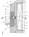
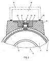
- FIGS. 1 and 2 show various sections through a portion of a first inventively designed magnetic coil assembly 10. It shows the FIG. 1 a longitudinal section through the magnet coil assembly 10 and the FIG. 2 a cross section along the line A - A in the FIG. 1 , Starting from the FIG. 2 show the FIG. 3 to clarify individual parts of the in the FIGS. 1 and 2 shown solenoid assembly 10 in the manner of an exploded drawing. The same components are provided with the same reference numerals.
- a bobbin 12 provided with a winding 11 is surrounded by a pot-shaped metal housing 13.
- prepared socket 14 are serving as a protective conductor terminal contact lug 15 and further contact lugs are arranged, to which the ends of the winding 11 are connected. The other tabs and the coil ends are for reasons of clarity in the FIGS. 1 to 3 not shown.
- the contact lug 15 is enclosed by the material of the plug-in socket 14 except for the region 15a projecting into a connection space 16.
- the contact lug 15 is inserted into the mold and then encapsulated with plastic.
- the connection space 16 is closed by a cap 17 shown schematically.
- a circumferential seal 18 prevents the ingress of moisture into the terminal space 16th
- a bolt-shaped metallic connecting part 21 is arranged in a recess 20 in a recess 20, a bolt-shaped metallic connecting part 21 is arranged.
- the contact lug 15 is both mechanically held on the metal housing 13 via the connecting part 21 and electrically connected thereto.
- O-ring 23 is arranged in a concentric with the recess 20 extending recess 22 of the socket 14 on the metal housing 13 side facing serving as a sealing part O-ring 23 is arranged.
- Both the recess 22 and the sealing region 21a of the connecting part 21 have a circular cross section in the sealing region.
- the inner diameter of the recess 22, the outer diameter of the sealing portion 21a and the O-ring 23 are matched to one another such that the O-ring seals radially.
- the recess 22 is greater in the axial direction of the connecting part 21 than the thickness of the O-ring 23.
- the O-ring 23 can thus escape in the axial direction.
- a collar 21b whose outer diameter is greater than the inner diameter of the recess 22, closes the recess 22. Its thickness determines the distance between the metal housing 13 and the socket 14. As in particular the FIG. 2 shows, the collar lies 21b due to the curvature of the metal housing 13 only linearly on this.
- the connecting part 21 is provided with a toothing 21 c, which is pressed into a corresponding through hole of the contact lug 15.
- the connecting part 21 is also provided with a further toothing 21 d, which is pressed into a corresponding through hole of the metal housing 13.
- An internal thread 21e allows the cap 17 to be fastened to the magnet coil arrangement 10 by a screw connection.
- the collar 21b also secures the connecting part 21 against being pulled out of the socket 14.
- the O-ring 23 Before the overmolding of the magnet coil arrangement 10, the O-ring 23 is pushed onto the sealing region 21a. Thereafter, the connecting member 21 is pressed with the O-ring 23 so far into the socket 14 until the collar 21b is flush with the socket 14. Thus, the recess 22 is closed so that no plastic gets into the recess 22 during the later encapsulation.
- the toothing 21d of the connecting part 21 is pressed into the metal housing 13 until the collar 21b touches the metal housing 13.
- the contact lug 15 is now electrically connected to the metal housing 13, and the socket 14 is held for the extrusion coating on the metal housing 13 in a defined position.
- the bobbin 12 provided with the winding 11 is guided into the metal housing 13 and the ends of the winding 11 are electrically conductively connected to the terminal lugs assigned to them.
- This structure is encapsulated in the usual way with plastic.
- the heated plastic flows into the open spaces and fills them out. After filling with plastic filled areas form after curing a plastic body in the FIGS. 1 and 2 is provided with the reference numeral 25.
- two side surfaces of the socket 14 are provided with projections 14 a and 14 b.
- the projections 14a and 14b are arranged between the outwardly facing side 14c and the metal housing 13 facing side 14d of the socket 14 and designed so that even with strong train on the socket 14 - either via the contact lug 15, via another contact lug or over the connecting part 21 - the socket 14 can not be pulled out of the plastic body 25.
- the metal housing 13 facing side 14d of the Stecksokkels 14 is provided with three recesses 14e, 14f, 14g.
- the recesses 14e, 14f, 14g surround the connecting part 21 concentrically as self-contained grooves. They serve as melt edges, which are melted during encapsulation of the magnet coil assembly 10 of the hot plastic and fuse with it.
- the melting temperature of the plastic used for the plastic body 25 is chosen higher than the melting temperature of the plastic used for the socket 14 for this purpose.
- the recesses 14e, 14f, 14g serve as so-called labyrinth seals, which prevent the transmission of moisture penetrated. In this way, it is possible to securely seal the interfaces between the socket 14 and the plastic body 25 against ingress of moisture.
- the recess 22 and the collar 21b of the connecting part 21 form a chamber with an annular cross-section, in which the O-ring 23 is protected during encapsulation from contact with the hot plastic compound. Since the O-ring 23 does not come into direct contact with the hot plastic, the thermal stress of the O-ring 23 during encapsulation is low. The mechanical stress of the O-ring 23 is low, since it only has to seal radially, but can dodge within the recess 22 in the direction of the axis of the connecting part 21.
- FIG. 4 shows a second magnet coil assembly 10 'according to the invention in one of FIG. 2 corresponding representation.
- the same parts are provided with the same reference numerals.
- the connection space 16 final cap is provided with the reference numeral 17 '.
- cap 17 is the cap 17 'with the seal 18 on the socket 14' on.
- the connecting part between the metal housing 13 and the contact lug 15 is denoted by the reference numeral 21 'provided.
- the O-ring 23 is axially sealingly disposed between the socket 14 'and a collar 21b' of the connecting part 21 '.
- the collar 21b ' limits the distance between the metal housing 13 and the socket 14'.
- the collar 21b ' determines the distance between the surfaces of the socket 14' and the connecting part 21 'against which the O-ring 23 abuts. This limits the force acting on the O-ring 23 in the direction of the axis of the connecting part 21 '. It is not necessary that the O-ring 23 in the radial direction sealingly against the connecting part 21 ', since the sealing effect is already effected by the force acting in the axial direction on the O-ring 23 force. Since the inner diameter of the collar 21b 'is greater than the outer diameter of the O-ring 23, the O-ring 23 can escape in axial direction under axial force.
- the collar 21b additionalally prevents the O-ring 23 from coming into contact with the hot plastic during encapsulation. Also in this embodiment, moisture that has penetrated via a gap between the metal housing 13 and the plastic body 25, only reach up to the O-ring 23. Due to the sealing by the O-ring 23, however, moisture that has penetrated can no longer enter the gap between the contact lug 15 and the plug-in base 14 ', via which the moisture would be conducted into the connection space 16.
- FIGS. 5 and 6 show various sections through a part of a third formed according to the invention magnetic coil assembly 10 " FIG. 5 a cut according to the FIG. 1 through the magnet coil arrangement 10 " FIG. 5 only the section is shown, in the magnet coil arrangement 10 "differs from that in the FIG. 1 shown magnetic coil assembly 10 differs.
- the FIG. 6 shows for clarification individual parts of the FIG. 5 shown magnetic coil assembly 10 "in an exploded view according to the FIG. 2 , The same components are provided with the same reference numerals.
- the third magnet coil arrangement 10 "differs from the one in the FIGS. 1 to 4 shown magnetic coil assemblies 10 and 10 'with respect to the arrangement of the contact lug 15 in the socket. This one is in the FIGS. 5 and 6 While in the magnetic coil assemblies 10 and 10 ', the contact lug 15 in the socket 14 (14 FIGS. 1 to 3 ) and 14 '( FIG. 4 ), the plug-in base 14 "is provided with an additional recess 28 which is arranged perpendicular to the recess 20 for receiving the connection part 21.
- the recess 28 serves to receive the area of the contact lug 15 provided with the reference numeral 15b 15b is provided with a through-hole 29.
- This arrangement has the advantage that in the production of the plug-in socket 14 ", the contact lug 15 does not need to be inserted into the injection mold.
- the contact lug 15 is introduced only before the encapsulation of the magnetic coil assembly 10 "in the recess 20 of the socket 14".
- the cap surrounding the terminal compartment is in the FIG. 5 not shown. She is - as in the FIG. 2 shown - form so that it rests on the plastic body 25.
Landscapes
- Physics & Mathematics (AREA)
- Electromagnetism (AREA)
- Engineering & Computer Science (AREA)
- Power Engineering (AREA)
- Electromagnets (AREA)
Abstract
Description
- Die Erfindung betrifft eine Magnetspulenanordnung, insbesondere zum Betätigen von Ventilen, gemäß dem Oberbegriff des Anspruchs 1.
- Eine derartige Magnetspulenanordnung ist aus der
DE 43 41 087 C2 bekannt. In einem Metallgehäuse ist ein Spulenkörper angeordnet, der mit einer elektrischen Wicklung versehen ist. Ein mit Kontaktfahnen versehener Stecksockel ist über ein metallisches Verbindungsteil an dem Metallgehäuse gehalten. Eine der Kontaktfahnen ist als Schutzleiteranschluß über das Verbindungsteil mit dem Metallgehäuse verbunden. An zwei weitere Kontaktfahnen sind die Enden der Spulenwicklungen angeschlossen. Die freien Räume zwischen dem bewickelten Spulenkörper, dem Metallgehäuse und dem Stecksockel sind mit Kunststoff ausgefüllt. Durch Spalten an den Grenzflächen zwischen dem Metallgehäuse und dem Kunststoff kann Feuchtigkeit in die Magnetspulenanordnung eindringen. Um zu verhindern, daß die Feuchtigkeit entlang der als Schutzleiteranschluß dienenden Kontaktfahne durch den Stecksockel in den Anschlußraum eintritt, ist zwischen der als Schutzleiteranschluß dienenden Kontaktfahne und dem Metallgehäuse ein das Verbindungsteil umschließender Dichtring vorgesehen. Bei der dem Umspritzen vorangehenden Montage wird das Verbindungsteil in eine Ausnehmung des Metallgehäuses und in eine ausnehmung der Kontaktfahne gepreßt. Dabei wird der Dichtring zwischen dem Metallgehäuse und der Kontaktfahne eingeklemmt. - Bedingt durch die Wölbung des Metallgehäuses ist der Abstand zwischen der Kontaktfahne und dem Metallgehäuse im Anlagebereich des Dichtrings unterschiedlich groß, so daß der Dichtring mehr oder weniger weit nach außen ausweicht. Dies führt zu einer ungleichmäßigen Verformung des Dichtrings über seinem Umfang. Die freie Umfangsfläche des Dichtrings, also die Fläche des Dichtrings, die nicht an einem Metallteil anliegt, kommt beim Umspritzen mit dem Kunststoff in Kontakt. Durch die hohe Temperatur des Kunststoffs während des Umspritzens wird das Material des Dichtrings thermisch stark beansprucht. Außerdem ist nicht sichergestellt, daß nach dem Erhärten des Kunststoffs, bei dem immer mit einem gewissen Schwund zu rechnen ist, eine einwandfreie Dichtwirkung zwischen dem Kunststoff und der vor dem Umspritzen freien Oberfläche des Dichtrings gewährleistet ist. Damit besteht die Gefahr, daß trotzdem Feuchtigkeit, die über einen Spalt zwischen Metallgehäuse und dem Kunststoff zu dem Dichtring gelangt ist, über einen Spalt zwischen dem Dichtring und dem an ihn grenzenden Kunststoff sowie über den Spalt zwischen der Kontaktfahne und dem Stecksockel oder über den Spalt zwischen der Kontaktfahne und dem Kunststoff in den Anschlußraum eintritt.
- Der Erfindung liegt die Aufgabe zugrunde, eine Magnetspulenanordnung der eingangs genannten Art zu schaffen, die eine Weiterleitung von Flüssigkeit, die über einen Spalt zwischen dem Metallgehäuse und dem an dieses angrenzenden Kunststoff in die Magnetspulenanordnung eingedrungen ist, in den Anschlußraum verhindert.
- Diese Aufgabe wird durch die im Anspruch 1 gekennzeichneten Merkmale gelöst. Bei der erfindungsgemäßen Magnetspulenanordnung berührt das Dichtteil weder die als Schutzleiteranschluß dienende Kontaktfahne noch das Metallgehäuse. Da die Kontaktfahne in dem Bereich, in dem das Verbindungsteil in diese eingreift, innerhalb des Stecksockels verläuft, genügt es, daß das Dichtteil einerseits an dem Verbindungsteil und andererseits an dem Stecksockel anliegt. Da das Dichtteil bereits vor dem Umspritzen der Magnetspulenanordnung mit Kraft beaufschlagt wird, spielt der Druck des Kunststoffs beim Umspritzen und in der darauf folgenden Abkühlphase für die Dichtwirkung keine Rolle. Auch der Schwund des Kunststoffs während des Abkühlens spielt für die Dichtwirkung keine Rolle. Das Dichtteil kann sowohl radial als auch axial dichtend zwischen dem Verbindungsteil und dem Stecksockel angeordnet werden.
- Vorteilhafte Weiterbildungen der Erfindung sind in den Unteransprüchen gekennzeichnet. Wird das Dichtteil radial dichtend angeordnet, ist es vorteilhaft, das Dichtteil in einer an die Außenkontur des Dichtteils angepaßten Ausnehmung des Stecksockels anzuordnen. Ist die Ausnehmung tiefer als die Dicke des Dichtteils, kann das Dichtteil in axialer Richtung ausweichen, d. h. es nimmt im eingebauten Zustand einen im wesentlichen ovalen bis eiförmigen Querschnitt an. Ein Bund des Verbindungsteils sorgt für einen definierten Abstand zwischen dem Metallgehäuse und der diesem zugewandten Fläche des Stecksockels. Ist der Außendurchmesser des Bunds größer als der Innendurchmesser der Ausnehmung, gelangt beim Umspritzen der Magnetspulenanordnung kein Kunststoff an das Dichtteil. Außerdem verhindert der an dem Stecksockel anliegende Teil des Bunds, daß das Verbindungsteil bei starkem Zug aus dem Stecksockel herausgezogen wird. Alternativ zu einer radial dichtenden Anordnung des Dichtteils erlaubt die Erfindung eine axial dichtende Anordnung des Dichtteils. In diesem Fall ist das Verbindungsteil mit einem Kragen versehen, der beim Einpressen des Verbindungsteils in die in dem Stecksockel gehaltene Kontaktfahne an dem Stecksockel zur Anlage kommt und so die auf das Dichtteil wirkende Kraft begrenzt. Zusätzlich verhindert der Kragen, daß das Dichtteil beim Umspritzen mit dem heißen Kunststoff in Berührung kommt. Ist das Verbindungsteil zumindest im Dichtbereich rotationssymmetrisch ausgebildet, kann als Dichtteil ein handelsüblicher und damit kostengünstiger O-Ring verwendet werden. Wird eine Seitenfläche des Stecksockels zwischen der nach außen weisenden Seite und der dem Metallgehäuse zugewandten Seite des Stecksockels mit einem Vorsprung versehen, ergibt sich eine formschlüssige Verbindung, die auch bei starkem Zug an den Kontaktfahnen oder an dem Verbindungsteil verhindert, daß der Stecksockel aus dem Kunststoffkörper herausgezogen wird. Eine oder mehrere Ausnehmungen auf der dem Metallgehäuse zugewandten Seite des Stecksockels, die das Verbindungsteil umgeben, verbessern die Dichtwirkung im Grenzbereich zwischen dem Stecksockel und dem zum Umspritzen verwendeten Kunststoff, wobei die Ausnehmungen ein Anschmelzen beim Umspritzen erleichtern oder als Labyrinthdichtung wirksam sind. Ist nur der Abschnitt der als Schutzleiteranschluß dienenden Kontaktfahne, in den das Verbindungsteil eingreift, in dem Stecksockel gehalten, vereinfacht sich die Herstellung des Stecksockels. Die Kontaktfahne wird nach der Herstellung des Stecksockels in eine Ausnehmung des Stecksockels eingeschoben. Dabei ist es vorteilhaft, diese Ausnehmung senkrecht zu der für das Verbindungsteil vorgesehenen Ausnehmung anzuordnen. Eine noch bessere Abdichtung gegen ein Eindringen von Feuchtigkeit in den Anschlußraum läßt sich erzielen, wenn die als Schutzleiteranschluß dienende Kontaktfahne nur in dem Stecksockel gehalten ist.
- Die Erfindung wird im folgenden mit ihren weiteren Einzelheiten anhand von in den Zeichnungen dargestellten Ausführungsbeispielen näher erläutert. Es zeigen
- Figur 1
- einen Längsschnitt durch einen Teil einer ersten erfindungsgemäß ausgebildeten Magnetspulenanordnung,
- Figur 2
- einen Schnitt entlang der Linie A - A in der
Figur 1 , - Figur 3
- einzelne Teile der in den
Figuren 1 und2 dargestellten Magnetspulenanordnung in der Art einer Explosionszeichnung, - Figur 4
- einen Schnitt entsprechend der
Figur 2 durch eine zweite erfindungsgemäße Magnetspulenanordnung, - Figur 5
- einen Schnitt entsprechend der
Figur 1 durch eine dritte erfindungsgemäße Magnetspulenanordnung und - Figur 6
- einzelne Teile der in der
Figur 5 dargestellten Magnetspulenanordnung in der Art einer Explosionszeichnung. - Die
Figuren 1 und2 zeigen verschiedene Schnitte durch einen Teil einer ersten erfindungsgemäß ausgebildeten Magnetspulenanordnung 10. Dabei zeigt dieFigur 1 einen Längsschnitt durch die Magnetspulenanordnung 10 und dieFigur 2 einen Querschnitt entlang der Linie A - A in derFigur 1 . Ausgehend von derFigur 2 zeigt dieFigur 3 zur Verdeutlichung einzelne Teile der in denFiguren 1 und2 dargestellten Magnetspulenanordnung 10 in der Art einer Explosionszeichnung. Gleiche Bauteile sind dabei mit denselben Bezugszeichen versehen. - Ein mit einer Wicklung 11 versehener Spulenkörper 12 ist von einem topfförmigen Metallgehäuse 13 umgeben. In einem aus elektrisch isolierenden Material, z. B. Kunststoff, hergestellten Stecksockel 14 sind eine als Schutzleiteranschluß dienende Kontaktfahne 15 sowie weitere Kontaktfahnen angeordnet, an die die Enden der Wicklung 11 angeschlossen sind. Die weiteren Kontaktfahnen sowie die Wicklungsenden sind aus Gründen der Übersichtlichkeit in den
Figuren 1 bis 3 nicht dargestellt. Die Kontaktfahne 15 ist bis auf den in einen Anschlußraum 16 ragenden Bereich 15a von dem Material des Stecksockels 14 umschlossen. Bei der Herstellung des Stecksockels 14 wird die Kontaktfahne 15 in die Spritzform eingelegt und danach mit Kunststoff umspritzt. In derFigur 2 ist der Anschlußraum 16 durch eine schematisch dargestellte Kappe 17 abgeschlossen. Eine umlaufende Dichtung 18 verhindert das Eindringen von Feuchtigkeit in den Anschlußraum 16. - In einer Ausnehmung 20 ist ein bolzenförmiges metallisches Verbindungsteil 21 angeordnet. Die Kontaktfahne 15 ist über das Verbindungsteil 21 sowohl mechanisch an dem Metallgehäuse 13 gehalten als auch elektrisch mit diesem verbunden. In einer konzentrisch zu der Ausnehmung 20 verlaufenden Ausnehmung 22 des Stecksockels 14 auf der dem Metallgehäuse 13 zugewandten Seite ist ein als Dichtteil dienender O-Ring 23 angeordnet. Sowohl die Ausnehmung 22 als auch der Dichtbereich 21a des Verbindungsteils 21 weisen im Dichtbereich einen kreisförmigen Querschnitt auf. Der Innendurchmesser der Ausnehmung 22, der Außendurchmesser des Dichtbereichs 21a und der O-Ring 23 sind derart aufeinander abgestimmt, daß der O-Ring radial dichtet. Die Ausnehmung 22 ist in Achsrichtung des Verbindungsteils 21 größer als die Dicke des O-Rings 23. Der O-Ring 23 kann somit in axialer Richtung ausweichen. Ein Bund 21b, dessen Außendurchmesser größer als der Innendurchmesser der Ausnehmung 22 ist, verschließt die Ausnehmung 22. Seine Dicke bestimmt den Abstand zwischen dem Metallgehäuse 13 und dem Stecksockel 14. Wie insbesondere die
Figur 2 zeigt, liegt der Bund 21b wegen der Wölbung des Metallgehäuses 13 nur linienförmig auf diesem auf. Das Verbindungsteil 21 ist mit einer Verzahnung 21c versehen, die in ein entsprechendes Durchgangsloch der Kontaktfahne 15 eingepreßt ist. Das Verbindungsteil 21 ist außerdem mit einer weiteren Verzahnung 21d versehen, die in ein entsprechendes Durchgangsloch des Metallgehäuses 13 eingepreßt ist. Ein Innengewinde 21e erlaubt es, die Kappe 17 durch eine Schraubverbindung an der Magnetspulenanordnung 10 zu befestigen. Der Bund 21b sichert außerdem das Verbindungsteil 21 gegen ein Herausziehen aus dem Stecksockel 14. - Vor dem Umspritzen der Magnetspulenanordnung 10 wird der O-Ring 23 auf den Dichtbereich 21a geschoben. Danach wird das Verbindungsteil 21 mit dem O-Ring 23 so weit in den Stecksockel 14 gepreßt, bis der Bund 21b bündig an dem Stecksockel 14 anliegt. Damit ist die Ausnehmung 22 derart verschlossen, daß beim späteren Umspritzen kein Kunststoff in die Ausnehmung 22 gelangt. In einem weiteren Schritt wird die Verzahnung 21d des Verbindungsteils 21 in das Metallgehäuse 13 gepreßt, bis der Bund 21b das Metallgehäuse 13 berührt. Die Kontaktfahne 15 ist jetzt mit dem Metallgehäuse 13 elektrisch verbunden, und der Stecksockel 14 ist für den Umspritzvorgang an dem Metallgehäuse 13 in einer definierten Lage gehalten. Nach diesen vorbereitenden Schritten wird der mit der Wicklung 11 versehene Spulenkörper 12 in das Metallgehäuse 13 geführt und die Enden der Wicklung 11 mit den ihnen zugeordneten Anschlußfahnen elektrisch leitend verbunden. Dieses Gebilde wird in üblicher Weise mit Kunststoff umspritzt. Dabei fließt der erhitzte Kunststoff in die freien Räume und füllt diese aus. Die nach dem Umspritzen mit Kunststoff gefüllten Bereiche bilden nach dem Aushärten einen Kunststoffkörper, der in den
Figuren 1 und2 mit dem Bezugszeichen 25 versehen ist. - Wie in der
Figur 1 dargestellt, sind zwei Seitenflächen des Stecksockels 14 sind mit Vorsprüngen 14a und 14b versehen. Die Vorsprünge 14a und 14b sind zwischen der nach außen weisenden Seite 14c und der dem Metallgehäuse 13 zugewandten Seite 14d des Stecksockels 14 angeordnet und so ausgebildet, daß auch bei starkem Zug an dem Stecksockel 14 - sei es über die Kontaktfahne 15, über eine andere Kontaktfahne oder über das Verbindungsteil 21 - der Stecksockel 14 nicht aus dem Kunststoffkörper 25 herausgezogen werden kann. - Die dem Metallgehäuse 13 zugewandte Seite 14d des Stecksokkels 14 ist mit drei Ausnehmungen 14e, 14f, 14g versehen. Die Ausnehmungen 14e, 14f, 14g umgeben das Verbindungsteil 21 konzentrisch als in sich geschlossene Rillen. Sie dienen als Schmelzkanten, die beim Umspritzen der Magnetspulenanordnung 10 von dem heißen Kunststoff angeschmolzen werden und mit diesem verschmelzen. Die Schmelztemperatur des für den Kunststoffkörper 25 verwendeten Kunststoffs wird hierfür höher gewählt als die Schmelztemperatur des für den Stecksockel 14 verwendeten Kunststoffs. Soweit eine vollständige Verschmelzung nicht stattfindet oder nicht beabsichtigt ist, dienen die Ausnehmungen 14e, 14f, 14g als sogenannte Labyrinthdichtungen, die eine Weiterleitung von eingedrungener Feuchtigkeit verhindern. Auf diese Weise ist es möglich, die Grenzflächen zwischen dem Stecksockel 14 und dem Kunststoffkörper 25 sicher gegen ein Eindringen von Feuchtigkeit abzudichten.
- Anders ist es dagegen bei den Grenzflächen zwischen Metall und Kunststoff, wie zwischen dem Metallgehäuse 13 und dem Kunststoffkörper 25 sowie zwischen der Kontaktfahne 15 und dem Stecksockel 14. Hier lassen sich Spalten, die ein Eindringen von Feuchtigkeit ermöglichten, nicht vermeiden. Es müssen daher zusätzliche Maßnahmen ergriffen werden, damit keine Feuchtigkeit, die von außen über einen Spalt zwischen dem Metallgehäuse 13 und dem Kunststoffkörper 25 eingedrungen ist, über einen Spalt zwischen der Kontaktfahne 15 und dem an diese angrenzenden Kunststoff des Stecksockels 14 in den Anschlußraum 16 gelangt. Gemäß der Erfindung ist hierfür der als Dichtteil dienende O-Ring 23 vorgesehen, der radial dichtend sowohl an dem Verbindungsteil 21 als auch an dem Stecksockel 14 anliegt. Nur bis hierhin kann Feuchtigkeit, die über einen Spalt zwischen dem Metallgehäuse 13 und dem Kunststoffkörper 25 eingedrungen ist, gelangen. In den Spalt zwischen der Kontaktfahne 15 und dem Stecksockel 14, über den Feuchtigkeit in den Anschlußraum 16 weitergeleitet würde, kann jedoch - wie oben beschrieben - wegen des O-Rings 23 keine Feuchtigkeit mehr gelangen.
- Die Ausnehmung 22 und der Bund 21b des Verbindungsteils 21 bilden eine Kammer mit kreisringförmigem Querschnitt, in der der O-Ring 23 beim Umspritzen vor einer Berührung mit der heißen Kunststoffmasse geschützt ist. Da der O-Ring 23 mit dem heißen Kunststoff nicht in direkte Berührung kommt, ist die thermische Beanspruchung des O-Rings 23 beim Umspritzen nur gering. Auch die mechanische Beanspruchung des O-Rings 23 ist gering, da er nur radial abdichten muß, in.Richtung der Achse des Verbindungsteils 21 jedoch innerhalb der Ausnehmung 22 ausweichen kann.
- Die
Figur 4 zeigt eine zweite Magnetspulenanordnung 10' gemäß der Erfindung in einer derFigur 2 entsprechende Darstellung. Dabei sind gleiche Teile mit den gleichen Bezugszeichen versehen. Die den Anschlußraum 16 abschließende Kappe ist mit dem Bezugszeichen 17' versehen. Anders als die in derFigur 2 dargestellte Kappe 17 liegt die Kappe 17' mit der Dichtung 18 auf dem Stecksockel 14' auf. Das Verbindungsteil zwischen dem Metallgehäuse 13 und der Kontaktfahne 15 ist mit dem Bezugszeichen 21' versehen. Der O-Ring 23 ist axial dichtend zwischen dem Stecksockel 14' und einem Kragen 21b' des Verbindungsteils 21' angeordnet. Der Kragen 21b' begrenzt den Abstand zwischen dem Metallgehäuse 13 und dem Stecksockel 14'. Außerdem bestimmt der Kragen 21b' den Abstand zwischen den Flächen von Stecksockel 14' und Verbindungsteil 21', an denen der O-Ring 23 anliegt. Damit wird die in Richtung der Achse des Verbindungsteils 21' auf den O-Ring 23 wirkende Kraft begrenzt. Es ist nicht erforderlich, daß der O-Ring 23 auch in radialer Richtung dichtend an dem Verbindungsteil 21' anliegt, da die Dichtwirkung bereits durch die in axialer Richtung auf den O-Ring 23 wirkende Kraft erfolgt. Da der Innendurchmesser des Kragens 21b' größer als der Außendurchmesser des O-Rings 23 ist, kann der O-Ring 23 bei axialer Kraftbeaufschlagung in radialer Richtung ausweichen. Der Kragen 21b' verhindert zusätzlich, daß der O-Ring 23 beim Umspritzen mit dem heißen Kunststoff in Berührung kommt. Auch in diesem Ausführungsbeispiel kann Feuchtigkeit, die über einen Spalt zwischen dem Metallgehäuse 13 und dem Kunststoffkörper 25 eingedrungen ist, nur bis zu dem O-Ring 23 gelangen. Aufgrund der Abdichtung durch den O-Ring 23 kann eingedrungene Feuchtigkeit jedoch nicht weiter in den Spalt zwischen der Kontaktfahne 15 und dem Stecksockel 14' gelangen, über den die Feuchtigkeit in den Anschlußraum 16 weitergeleitet würde. - Die
Figuren 5 und 6 zeigen verschiedene Schnitte durch einen Teil einer dritten gemäß der Erfindung ausgebildeten Magnetspulenanordnung 10". Dabei zeigt dieFigur 5 einen Schnitt entsprechend derFigur 1 durch die Magnetspulenanordnung 10". In derFigur 5 ist nur derjenige Ausschnitt dargestellt, in dem sich die Magnetspulenanordnung 10" von der in derFigur 1 dargestellten Magnetspulenanordnung 10 unterscheidet. DieFigur 6 zeigt zur Verdeutlichung einzelne Teile der in derFigur 5 dargestellten Magnetspulenanordnung 10" in einer Explosionszeichnung entsprechend derFigur 2 . Gleiche Bauteile sind dabei mit den gleichen Bezugszeichen versehen. - Die dritte Magnetspulenanordnung 10" unterscheidet sich von den in den
Figuren 1 bis 4 dargestellten Magnetspulenanordnungen 10 und 10' hinsichtlich der Anordnung der Kontaktfahne 15 in dem Stecksockel. Dieser ist in denFiguren 5 und 6 mit dem Bezugszeichen 14" versehen. Während bei den Magnetspulenanordnungen 10 und 10' die Kontaktfahne 15 in die Stecksockel 14 (Figuren 1 bis 3 ) und 14' (Figur 4 ) eingespritzt ist, ist der Stecksockel 14" mit einer zusätzlichen Ausnehmung 28 versehen, die senkrecht zu der Ausnehmung 20 für die Aufnahme des Verbindungsteils 21 angeordnet ist. Die Ausnehmung 28 dient zur Aufnahme des mit dem Bezugszeichen 15b versehenen Bereichs der Kontaktfahne 15. Der Bereich 15b ist mit einem Durchgangsloch 29 versehen. Diese Anordnung hat den Vorteil, daß bei der Herstellung des Stecksockels 14" die Kontaktfahne 15 nicht in die Spritzform eingelegt zu werden braucht. Die Kontaktfahne 15 wird erst vor dem Umspritzen der Magnetspulenanordnung 10" in die Ausnehmung 20 des Stecksockels 14" eingeführt. Nachdem der O-Ring 23 bis zur Anlage an dem Bund 21b auf das Verbindungsteil 21 geschoben worden ist, wird das Verbindungsteil 21 mit dem O-Ring 23 in die Ausnehmung 20 geschoben und der Kontaktbereich 21c des Verbindungsteils 21 in das Durchgangsloch 29 der Kontaktfahne 15 gepreßt, bis der Bund 21b an dem Stecksockel 14" anliegt. Damit ist die Kontaktfahne 15 bei den weiteren Verarbeitungsschritten gegen ein Herausrutschen aus dem Stecksockel 14" gesichert. Nach dem Einpressen der Verzahnung 21d des Verbindungsteils 21 in das Metallgehäuse 13 erfolgen die weiteren Verarbeitungsschritte wie bereits im Zusammenhang mit derFigur 3 beschrieben. - Die den Anschlußraum umgebende Kappe ist in der
Figur 5 nicht dargestellt. Sie ist - wie in derFigur 2 dargestellt - so auszubilden, daß sie auf dem Kunststoffkörper 25 aufliegt.
Claims (13)
- Magnetspulenanordnung, insbesondere zum Betätigen von Ventilen,- mit einem bewickelten Spulenkörper,- mit einem den bewickelten Spulenkörper umgebenden Metallgehäuse,- mit einem mit Kontaktfahnen versehenen Stecksockel, von denen eine als Schutzleiteranschluß dient,- mit einem zwischen dem Metallgehäuse und der als Schutzleiteranschluß dienenden Kontaktfahne angeordneten metallischen Verbindungsteil, das in eine Ausnehmung des Metallgehäuses und der als Schutzleiteranschluß dienenden Kontaktfahne eingreift,- mit einem das Verbindungsteil umgebenden ringförmigen Dichtteil und- bei der die freien Räume zwischen dem bewickelten Spulenkörper, dem Metallgehäuse und dem Stecksockel mit Kunststoff gefüllt sind,dadurch gekennzeichnet,- daß die als Schutzleiteranschluß dienende Kontaktfahne (15) in dem Bereich, in dem das Verbindungsteil (21; 21') in diese eingreift, innerhalb des Stecksockels (14; 14'; 14") angeordnet ist und- daß das Dichtteil (23) zwischen dem Verbindungsteil (21; 21') und dem Stecksockel (14; 14'; 14") dichtend angeordnet ist.
- Magnetspulenanordnung nach Anspruch 1, dadurch gekennzeichnet, daß das Dichtteil (23) in radialer Richtung dichtend zwischen dem Verbindungsteil (21) und dem Stecksockel (14; 14") angeordnet ist.
- Magnetspulenanordnung nach Anspruch 2, dadurch gekennzeichnet, daß der Stecksockel (14; 14") an der dem Metallgehäuse (13) zugewandten Seite mit einer an die Außenkontur des Dichtteils (23) angepaßten Ausnehmung (22) versehen ist.
- Magnetspulenanordnung nach Anspruch 3, dadurch gekennzeichnet, daß die Ausnehmung (22) tiefer als die Dicke des Dichtteils (23) ist.
- Magnetspulenanordnung nach einem der vorhergehenden Ansprüche, dadurch gekennzeichnet, daß das Verbindungsteil (21) zwischen dem in das Metallgehäuse (13) eingreifenden Teil (21d) und dem Teil (21a), der von dem Dichtteil (23) umschlossen ist, mit einem Bund (21b) versehen ist.
- Magnetspulenanordnung nach Anspruch 5 in Verbindung mit Anspruch 4, dadurch gekennzeichnet, daß der Außendurchmesser des Bunds (21b) größer als der Durchmesser der Ausnehmung (22) ist.
- Magnetspulenanordnung nach Anspruch 1, dadurch gekennzeichnet, daß das Dichtteil (23) in axialer Richtung dichtend zwischen dem Verbindungsteil (21') und dem Stecksockel (14') angeordnet ist, daß das Verbindungsteil (21') mit einem Kragen (21b') versehen ist, der das Dichtteil (23) in axialer Richtung gegen den Stecksockel (14') drückt und daß der Kragen (21b') das Dichtteil (23) seitlich umschließt.
- Magnetspulenanordnung nach einem der vorhergehenden Ansprüche, dadurch gekennzeichnet, daß das Verbindungsteil (21; 21') rotationssymmetrisch ausgebildet ist und daß das Dichtteil (23) ein O-Ring ist.
- Magnetspulenanordnung nach einem der vorhergehenden Ansprüche, dadurch gekennzeichnet, daß mindestens eine Seitenfläche des Stecksockels (14) zwischen der nach außen weisenden Seite (14c) und der dem Metallgehäuse (13) zugewandten Seite (14d) des Stecksockels (14) mit einem Vorsprung (14a, 14b) versehen ist.
- Magnetspulenanordnung nach einem der vorhergehenden Ansprüche, dadurch gekennzeichnet, daß die dem Metallgehäuse (13) zugewandte Seite (14b) des Stecksockels (14) mit mindestens einer das Verbindungsteil (21) umgebenden Ausnehmung (14e, 14f, 14g) versehen ist.
- Magnetspulenanordnung nach einem der vorhergehenden Ansprüche, dadurch gekennzeichnet, daß der Stecksockel (14") mit einer ersten Ausnehmung (20) für die Aufnahme des Verbindungsteils (21) und mit einer zweiten Ausnehmung (28) für die Aufnahme des Bereichs der als Schutzleiteranschluß dienenden Kontaktfahne (15), in den das Verbindungsteil (21) eingreift, versehen ist.
- Magnetspulenanordnüng nach Anspruch 11, dadurch gekennzeichnet, daß die zweite Ausnehmung (28) senkrecht zu der ersten Ausnehmung (20) angeordnet ist.
- Magnetspulenanordnung nach einem der Ansprüche 1 bis 10, dadurch gekennzeichnet, daß die als Schutzleiteranschluß dienende Kontaktfahne (15) nur in dem Stecksockel (14; 14') verläuft.
Applications Claiming Priority (5)
| Application Number | Priority Date | Filing Date | Title |
|---|---|---|---|
| DE10025719 | 2000-05-25 | ||
| DE10025719 | 2000-05-25 | ||
| DE10049709 | 2000-10-07 | ||
| DE10049709A DE10049709A1 (de) | 2000-05-25 | 2000-10-07 | Magnetspulenanordnung |
| PCT/EP2001/004748 WO2001091140A1 (de) | 2000-05-25 | 2001-04-27 | Magnetspulenanordnung |
Publications (2)
| Publication Number | Publication Date |
|---|---|
| EP1284003A1 EP1284003A1 (de) | 2003-02-19 |
| EP1284003B1 true EP1284003B1 (de) | 2009-12-02 |
Family
ID=26005813
Family Applications (1)
| Application Number | Title | Priority Date | Filing Date |
|---|---|---|---|
| EP01931659A Expired - Lifetime EP1284003B1 (de) | 2000-05-25 | 2001-04-27 | Magnetspulenanordnung |
Country Status (3)
| Country | Link |
|---|---|
| US (1) | US6784778B2 (de) |
| EP (1) | EP1284003B1 (de) |
| WO (1) | WO2001091140A1 (de) |
Families Citing this family (8)
| Publication number | Priority date | Publication date | Assignee | Title |
|---|---|---|---|---|
| DE102004029185A1 (de) * | 2004-06-16 | 2006-01-12 | Hydac Electronic Gmbh | Betätigungsvorrichtung |
| US7517235B2 (en) | 2006-12-28 | 2009-04-14 | General Electric Company | Press fit connection for mounting electrical plug-in outlet insulator to a busway aluminum housing |
| DE202007005132U1 (de) * | 2007-04-04 | 2008-08-14 | Eto Magnetic Gmbh | Elektromagnetische Stellvorrichtung |
| DE102010055212A1 (de) * | 2010-12-20 | 2012-06-21 | Svm Schultz Verwaltungs-Gmbh & Co. Kg | Elektromagnet mit einem Anschlussbereich |
| US9431834B2 (en) | 2012-03-20 | 2016-08-30 | Qualcomm Incorporated | Wireless power transfer apparatus and method of manufacture |
| US9653206B2 (en) | 2012-03-20 | 2017-05-16 | Qualcomm Incorporated | Wireless power charging pad and method of construction |
| US9160205B2 (en) | 2012-03-20 | 2015-10-13 | Qualcomm Incorporated | Magnetically permeable structures |
| US9583259B2 (en) | 2012-03-20 | 2017-02-28 | Qualcomm Incorporated | Wireless power transfer device and method of manufacture |
Family Cites Families (14)
| Publication number | Priority date | Publication date | Assignee | Title |
|---|---|---|---|---|
| US4683454A (en) * | 1985-10-31 | 1987-07-28 | Automatic Switch Company | Solenoid actuator with electrical connection modules |
| US4682136A (en) * | 1985-11-26 | 1987-07-21 | United Technologies Automotive, Inc. | Fused covering for an electrical conductor and method for making the fused covering |
| IT213013Z2 (it) | 1987-11-24 | 1989-10-13 | Weber Srl | Bobina di eccitazione per una valvola di dosatura e di polverizzazione del carburante per un dispositivo ad iniezione del carburante in un motore a combustione interna |
| FR2640413B1 (fr) * | 1988-12-12 | 1993-04-02 | Mors | Agencement a bobine electrique, notamment electro-aimant, comprenant une carcasse de bobine et un capot de bobine |
| US5204044A (en) * | 1989-03-28 | 1993-04-20 | Aisan Kogyo Kabushiki Kaisha | Method of asembling a DC solenoid with a thermistor |
| DE4341087C2 (de) | 1993-12-02 | 1996-02-08 | Bso Steuerungstechnik Gmbh | Abgedichtete Schaltvorrichtung |
| KR100420662B1 (ko) * | 1995-09-08 | 2004-06-05 | 도토기키 가부시키가이샤 | 솔레노이드및솔레노이드밸브 |
| DE19622634A1 (de) * | 1996-06-05 | 1997-12-11 | Nass Magnet Gmbh | Magnetspule sowie Verfahren zu deren Herstellung |
| US5710535A (en) * | 1996-12-06 | 1998-01-20 | Caterpillar Inc. | Coil assembly for a solenoid valve |
| US6127912A (en) * | 1998-08-03 | 2000-10-03 | Caterpillar Inc. | Bobbin for an encapsulated coil of a solenoid assembly |
| US6121865A (en) | 1998-08-03 | 2000-09-19 | Caterpillar Inc. | Solenoid assembly having a sealing device for the electrical leads |
| DE19854100B4 (de) * | 1998-11-24 | 2013-10-10 | Bosch Rexroth Aktiengesellschaft | Magnetspulenanordnung |
| DE19958199A1 (de) * | 1998-12-11 | 2000-06-29 | Continental Teves Inc | Elektrischer Verbinder zum Herstellen einer lötfreien Verbindung zwischen einer Spule und einer Leiterplatte |
| US6310533B2 (en) * | 1999-07-20 | 2001-10-30 | Cliftronics, Inc. | Water-resistant encapsulation of solenoid |
-
2001
- 2001-04-27 US US10/276,534 patent/US6784778B2/en not_active Expired - Fee Related
- 2001-04-27 EP EP01931659A patent/EP1284003B1/de not_active Expired - Lifetime
- 2001-04-27 WO PCT/EP2001/004748 patent/WO2001091140A1/de not_active Ceased
Also Published As
| Publication number | Publication date |
|---|---|
| US6784778B2 (en) | 2004-08-31 |
| WO2001091140A1 (de) | 2001-11-29 |
| US20040104795A1 (en) | 2004-06-03 |
| EP1284003A1 (de) | 2003-02-19 |
Similar Documents
| Publication | Publication Date | Title |
|---|---|---|
| DE69411642T2 (de) | Vergossenes elektromagnetisch betätigtes Ventil | |
| DE3153393C2 (de) | ||
| EP2076908B1 (de) | Elektrische durchführung, insbesondere für druckanwendungen, sowie verfahren zum herstellen einer solchen durchführung | |
| DE202007010865U1 (de) | Elektrische Heizpatrone | |
| EP2896093B1 (de) | Elektrischer kontaktstecker sowie steckergehäuse | |
| EP3619781B1 (de) | Elektro-bauteil und verfahren zu dessen herstellung | |
| EP1356480B1 (de) | Abgedichtete schaltvorrichtung | |
| DE102011052576B3 (de) | Elektrische Vorrichtung mit Dichtelement, Dichtelement für eine elektrische Vorrichtung und Verfahren zum Abdichten eines Gehäuses | |
| EP1284003A1 (de) | Magnetspulenanordnung | |
| WO2007048434A1 (de) | Fluidleitung und verfahren zu ihrer herstellung | |
| DE102015224152B3 (de) | Betätigungsvorrichtung mit Polscheibe und Distanzscheibe | |
| EP0913882A2 (de) | Verfahren zum Isolieren eines elektrischen Bauteiles | |
| DE4341087C2 (de) | Abgedichtete Schaltvorrichtung | |
| DE4343879A1 (de) | Elektromagnet, insbesondere für ein hydraulisches Ventil | |
| DE10049709A1 (de) | Magnetspulenanordnung | |
| DE10054714A1 (de) | Verfahren zum Abdichten eines Kabels in/an einem Kabeldurchführungskanal sowie ein Kabeldurchführungskanal | |
| DE4310156C2 (de) | Gegen Umgebungseinflüsse geschützte Spulenvorrichtung, insbesondere Solenoid | |
| DE2341112A1 (de) | Verschlussgehaeuse fuer kabelenden | |
| DE102005033212B4 (de) | Hochspannungssicherung | |
| DE10108350C1 (de) | Baueinheit aus einem Näherungsschalter und einem Kabelanschlußteil und Verfahren zu deren Herstellung | |
| DE102004010904A1 (de) | Verfahren zur Herstellung einer Vorrichtung zur Erfassung der Bewegung eines bewegbaren Bauteils | |
| DE2820132C3 (de) | Elektrische Anschlußeinrichtung | |
| DE3942511C1 (de) | ||
| DE3741103C2 (de) | ||
| DE102005014373B3 (de) | Elektrische Steckvorrichtung |
Legal Events
| Date | Code | Title | Description |
|---|---|---|---|
| PUAI | Public reference made under article 153(3) epc to a published international application that has entered the european phase |
Free format text: ORIGINAL CODE: 0009012 |
|
| 17P | Request for examination filed |
Effective date: 20021106 |
|
| AK | Designated contracting states |
Designated state(s): AT BE CH CY DE DK ES FI FR GB GR IE IT LI LU MC NL PT SE TR |
|
| RIN1 | Information on inventor provided before grant (corrected) |
Inventor name: STITZ, MATTHIAS Inventor name: RICHARTZ, ACHIM |
|
| RBV | Designated contracting states (corrected) |
Designated state(s): DE FR GB IT |
|
| GRAP | Despatch of communication of intention to grant a patent |
Free format text: ORIGINAL CODE: EPIDOSNIGR1 |
|
| GRAS | Grant fee paid |
Free format text: ORIGINAL CODE: EPIDOSNIGR3 |
|
| GRAA | (expected) grant |
Free format text: ORIGINAL CODE: 0009210 |
|
| AK | Designated contracting states |
Kind code of ref document: B1 Designated state(s): DE FR GB IT |
|
| REG | Reference to a national code |
Ref country code: GB Ref legal event code: FG4D Free format text: NOT ENGLISH |
|
| REF | Corresponds to: |
Ref document number: 50115245 Country of ref document: DE Date of ref document: 20100114 Kind code of ref document: P |
|
| PLBE | No opposition filed within time limit |
Free format text: ORIGINAL CODE: 0009261 |
|
| STAA | Information on the status of an ep patent application or granted ep patent |
Free format text: STATUS: NO OPPOSITION FILED WITHIN TIME LIMIT |
|
| 26N | No opposition filed |
Effective date: 20100903 |
|
| PG25 | Lapsed in a contracting state [announced via postgrant information from national office to epo] |
Ref country code: IT Free format text: LAPSE BECAUSE OF FAILURE TO SUBMIT A TRANSLATION OF THE DESCRIPTION OR TO PAY THE FEE WITHIN THE PRESCRIBED TIME-LIMIT Effective date: 20091202 |
|
| PGFP | Annual fee paid to national office [announced via postgrant information from national office to epo] |
Ref country code: GB Payment date: 20120423 Year of fee payment: 12 Ref country code: FR Payment date: 20120511 Year of fee payment: 12 |
|
| PGFP | Annual fee paid to national office [announced via postgrant information from national office to epo] |
Ref country code: DE Payment date: 20120626 Year of fee payment: 12 |
|
| GBPC | Gb: european patent ceased through non-payment of renewal fee |
Effective date: 20130427 |
|
| PG25 | Lapsed in a contracting state [announced via postgrant information from national office to epo] |
Ref country code: DE Free format text: LAPSE BECAUSE OF NON-PAYMENT OF DUE FEES Effective date: 20131101 Ref country code: GB Free format text: LAPSE BECAUSE OF NON-PAYMENT OF DUE FEES Effective date: 20130427 |
|
| REG | Reference to a national code |
Ref country code: FR Ref legal event code: ST Effective date: 20131231 |
|
| REG | Reference to a national code |
Ref country code: DE Ref legal event code: R119 Ref document number: 50115245 Country of ref document: DE Effective date: 20131101 |
|
| PG25 | Lapsed in a contracting state [announced via postgrant information from national office to epo] |
Ref country code: FR Free format text: LAPSE BECAUSE OF NON-PAYMENT OF DUE FEES Effective date: 20130430 |