EP1283084A1 - Funkenerosionsmaschine und funkenerosionsbearbeitungsverfahren - Google Patents
Funkenerosionsmaschine und funkenerosionsbearbeitungsverfahren Download PDFInfo
- Publication number
- EP1283084A1 EP1283084A1 EP00927768A EP00927768A EP1283084A1 EP 1283084 A1 EP1283084 A1 EP 1283084A1 EP 00927768 A EP00927768 A EP 00927768A EP 00927768 A EP00927768 A EP 00927768A EP 1283084 A1 EP1283084 A1 EP 1283084A1
- Authority
- EP
- European Patent Office
- Prior art keywords
- predetermined
- jump
- command locus
- jump operation
- value
- Prior art date
- Legal status (The legal status is an assumption and is not a legal conclusion. Google has not performed a legal analysis and makes no representation as to the accuracy of the status listed.)
- Granted
Links
Images


Classifications
-
- B—PERFORMING OPERATIONS; TRANSPORTING
- B23—MACHINE TOOLS; METAL-WORKING NOT OTHERWISE PROVIDED FOR
- B23H—WORKING OF METAL BY THE ACTION OF A HIGH CONCENTRATION OF ELECTRIC CURRENT ON A WORKPIECE USING AN ELECTRODE WHICH TAKES THE PLACE OF A TOOL; SUCH WORKING COMBINED WITH OTHER FORMS OF WORKING OF METAL
- B23H7/00—Processes or apparatus applicable to both electrical discharge machining and electrochemical machining
- B23H7/14—Electric circuits specially adapted therefor, e.g. power supply
- B23H7/18—Electric circuits specially adapted therefor, e.g. power supply for maintaining or controlling the desired spacing between electrode and workpiece
-
- B—PERFORMING OPERATIONS; TRANSPORTING
- B23—MACHINE TOOLS; METAL-WORKING NOT OTHERWISE PROVIDED FOR
- B23H—WORKING OF METAL BY THE ACTION OF A HIGH CONCENTRATION OF ELECTRIC CURRENT ON A WORKPIECE USING AN ELECTRODE WHICH TAKES THE PLACE OF A TOOL; SUCH WORKING COMBINED WITH OTHER FORMS OF WORKING OF METAL
- B23H1/00—Electrical discharge machining, i.e. removing metal with a series of rapidly recurring electrical discharges between an electrode and a workpiece in the presence of a fluid dielectric
- B23H1/02—Electric circuits specially adapted therefor, e.g. power supply, control, preventing short circuits or other abnormal discharges
Definitions
- the present invention relates to a technology for machining an object by generating an electric discharge between the object and an electrode. More particularly, this invention relates to a technology for controlling a jump operation in which distance between the object and the electrode is temporarily increased at every predetermined time or depending on the machining state.
- an electric discharge machining device performs jump operation.
- This jump operation is an operation in which distance between the object and the electrode ("interelectrode distance") is temporarily increased at every predetermined time or depending on the machining state. Machining waste deposited between the electrode and the object can be removed efficiently because of this jump operation. Moreover, speed or precision of electric discharge machining can be improved.
- Fig. 14 is a block diagram showing the configuration of a conventional electric discharge machining device.
- Fig. 15 includes time charts for explaining a jump operation performed by the conventional electric discharge machining device.
- Fig. 15(a) is a time chart showing a change in interelectrode distance in the jump operation
- Fig. 15(b) is a time chart showing a change in speed in the jump operation
- Fig. 15(c) is a time chart showing a change in acceleration in the jump operation
- Fig. 15(d) is a graph showing a result of Fourier transform of the time chart in Fig. 15(a).
- the interelectrode voltage detection unit 7 detects a voltage between the electrode 11 and the object 12 ("interelectrode voltage").
- the interelectrode servo control unit 3 controls the position of the main shaft 13 according to the detected interelectrode voltage.
- the interelectrode servo control unit 3 performs electric discharge machining of the object 12 by using an electric discharge phenomenon.
- the jump control unit 102 performs a control for temporarily increasing the interelectrode distance at every predetermined time or a depending on the machining state. Whether machining by the interelectrode servo control unit 3 is to be performed or jump operation by the jump control unit 102 is to be performed can be selected with the switching unit SW10.
- the jump control unit 102 When the jump control unit 102 performs a jump operation, the jump control unit 102 notifies the interelectrode servo control unit 3 the jump operation is performed, and switches the switching unit SW10 from the interelectrode servo control unit 3 to the jump control unit 102.
- the jump control unit 102 starts the jump operation at a point of time at which predetermined time has elapsed or a point of time t1 at which a predetermined machining state is set.
- the electrode 11 is raised at a speed V1 until the interelectrode distance changes from a distance l1 to a distance l2.
- the electrode 11 is switched from an up state to a down state to move the electrode 11 downward at a speed -V1.
- the speed -V1 of the of the electrode 11 is changed into the speed -V2, and the electrode 11 is reduced in speed, and the interelectrode distance returns to the distance l1.
- the speed -V1 is reduced to the speed -V2 because the electrode 11 may collide with the object to be machined 12 by inertia of the electrode 11 when the electrode 11 is moved downward at the speed -V1.
- a deceleration distance (l3 - l1) may be increased to prevent a machining precision from being degraded by the influence of residual vibration or the overshooting of the shaft.
- a deceleration distance (l3 - l1) may be increased to prevent a machining precision from being degraded by the influence of residual vibration or the overshooting of the shaft.
- a jump operation performed by the conventional electric discharge machining device has a problem a machining precision or a machining speed is considerably decreased depending on a setting of residual vibration or deceleration distance because a speed or an acceleration is sharply changed.
- an optimum set frequency and the allowable maximum component value of the frequency in the jump operation change depending on the mass of the electric discharge machining device, a machining condition, aging of the electric discharge machining device, and the like.
- the machining time is shortened, and the machining precision can be increased.
- An operator of the electric discharge machining device is hard to optimally adjust the set frequency and the allowable maximum component value.
- This invention has been made to solve the above problems, and has as its object to obtain an electric discharge machining device and an electric discharge machining method which can shorten machining time and which can improve a machining precision.
- the electric discharge machining device comprises an interelectrode servo control unit which controls an interelectrode distance which is a distance between an electrode and an object to be machined while applying a predetermined voltage across the electrode and the object; and a jump control unit which controls a jump operation in which the interelectrode distance is temporarily increased at every predetermined time or depending on a machining state.
- the jump control unit includes a command locus generation unit which generates a smooth command locus having a frequency component in a predetermined frequency range which is not higher than a predetermined frequency or lower than the predetermined frequency.
- the jump control unit controls the jump operation by using a smooth command locus generated by the command locus generation unit.
- the command locus generation unit is designed to generate a command locus by using a sine wave having a low-frequency component which is lower than a resonance frequency of a mechanical system, vibration of the mechanical system does not remain upon completion of the jump operation, and precise machining can be performed.
- the electric discharge machining device comprises an interelectrode servo control unit which controls an interelectrode distance which is a distance between an electrode and an object while applying a predetermined voltage across the electrode and the object; and a jump control unit which controls a jump operation in which the interelectrode distance is temporarily increased at every predetermined time or depending on a machining state.
- the jump control unit includes a command locus generation unit which generates a smooth command locus having a frequency component in a predetermined frequency range except for a frequency range of a first frequency which is lower than a predetermined frequency to a second frequency which is higher than the predetermined frequency.
- the jump control unit controls the jump operation by using the smooth command locus generated by the command locus generation unit.
- the command locus generation unit is designed to generate a command locus by using a sine wave having a frequency component sufficiently different from a resonance frequency of a mechanical system, vibration of the mechanical system does not remain upon completion of the jump operation, and precise machining can be performed.
- the electric discharge machining device comprises an interelectrode servo control unit which controls an interelectrode distance which is a distance between an electrode and an object while applying a predetermined voltage across the electrode and the object; and a jump control unit which controls a jump operation in which the interelectrode distance is temporarily increased at every predetermined time or depending on a machining state.
- the jump control unit includes a command locus generation unit which generates a smooth command locus in which a value of a frequency component in a predetermined frequency range which is not lower than a predetermined frequency or higher than the predetermined frequency is suppressed to a value which is not larger than a predetermined value or smaller than the predetermined value.
- the jump control unit controls the jump operation by using the smooth command locus generated by the command locus generation unit.
- the command locus generation unit is designed to generate a smooth command locus in which a high frequency component which is higher than a resonance frequency of a mechanical system is suppressed to a value which is not larger than a predetermined value, vibration of the mechanical system does not remain upon completion of the jump operation, precise machining can be performed, and a deceleration distance of the electrode can be decreased by decreasing vibration and decreasing an amount of overshooting. As a result, time required for the entire jump operation can be shortened, and machining speed can be increased.
- the electric discharge machining device comprises an interelectrode servo control unit which controls an interelectrode distance which is a distance between an electrode and an object while applying a predetermined voltage across the electrode and the object; and a jump control unit which controls a jump operation in which the interelectrode distance is temporarily increased at every predetermined time or depending on a machining state.
- the jump control unit includes a command locus generation unit which generates a smooth command locus in which a value of a frequency component in a predetermined frequency range of a first frequency which is lower than a predetermined frequency to a second frequency which is higher than the predetermined frequency is suppressed to a value which is not larger than a predetermined value or smaller than the predetermined value.
- the jump control unit controls the jump operation by using the smooth command locus generated by the command locus generation unit.
- the command locus generation unit is designed to generate a smooth command locus in which a value of a frequency component approximate to a resonance frequency of a mechanical system, vibration of the mechanical system does not remain upon completion of the jump operation, and precise machining can be performed.
- the jump control unit further includes a filter, and the filter shapes a locus into a smooth locus in which the value of the frequency component in the predetermined frequency range is suppressed to a value which is not larger than the predetermined value or smaller than the predetermined value.
- a filter shapes a locus into a smooth locus in which the value of the frequency component in the predetermined frequency range is suppressed to a value which is not larger than the predetermined value or smaller than the predetermined value.
- the command locus generation unit adds a plurality of loci in each of which the value of the frequency component in the predetermined frequency range is suppressed to a value which is not larger than a predetermined value or smaller than the predetermined value to each other to generate the smooth command locus which is suppressed to the value which is not larger than the predetermined value or smaller than the predetermined value. In this manner, vibration of a mechanical system does not remain upon completion of the jump operation, and precise machining can be performed.
- the electric discharge machining device further includes a storage unit which stores condition information of the jump operation including the predetermined frequency range or the predetermined frequency range and the predetermined value, and the command locus generation unit is designed to generate the smooth command locus on the basis of the predetermined frequency range or the predetermined frequency range and the predetermined value, so that the jump operation can be flexibly changed and set.
- the electric discharge machining device further includes setting input unit which inputs values of the predetermined frequency range or at least one of the predetermined frequency range and the predetermined value, and the command locus generation unit generates the smooth command locus on the basis of the predetermined frequency range or the predetermined frequency and the predetermined value set by the setting input unit. In this manner, vibration of a mechanical system does not remain upon completion of the jump operation, so that precise machining can be easily set.
- the jump control unit further includes a jump operation evaluation unit which detects a state in the jump operation to evaluate the jump operation, and a setting change unit which changes the set values of the predetermined frequency range, the predetermined value, or the predetermined frequency range and the predetermined value on the basis of an evaluation result obtained by the jump operation evaluation unit.
- the jump operation evaluation unit evaluates an actual motion of the electrode, and the setting change unit automatically change a setting on the basis of the evaluation result to obtain an optimum machining condition such as the predetermined frequency range or the predetermined value. For this reason, machining at a high speed and a high precision can be automatically performed.
- the command locus generation unit generates a predetermined function which satisfies the predetermined frequency range or the predetermined frequency range and the predetermined value and which corresponds to the jump operation, and performs at least one integrating process or at least one differential process to the predetermined function to generate the command locus or a control command corresponding to the command locus.
- vibration of a mechanical system does not remain upon completion of the jump operation, and precise machining can be performed.
- deceleration distance of the electrode can be shortened by reducing vibration and reducing an amount of overshooting. As a result, time required for the entire jump operation can be shortened, and machining speed can be increased.
- the jump control unit controls the jump operation on the basis of a command speed or a command acceleration corresponding to the smooth command locus . In this manner, flexible electric discharge machining can be performed at a high speed and high precision.
- the electric discharge machining method in which an interelectrode servo control unit controls an interelectrode distance which is a distance between an electrode and an object while applying a predetermined voltage across the electrode and the object and a jump control unit controls a jump operation temporarily increases the interelectrode distance every predetermined time or depending on a machining state.
- the method comprises the command locus generation step of generating a smooth command locus having a frequency component in a predetermined frequency range which is not higher than a predetermined frequency or lower than the predetermined frequency, and the jump operation control step of controlling the jump operation by using a smooth command locus generated by the command locus generation step.
- the command locus generation step is designed to generate a command locus by using a sine wave having a low-frequency component which is lower than a resonance frequency of a mechanical system, vibration of the mechanical system does not remain upon completion of the jump operation, and precise machining can be performed.
- the electric discharge machining method in which an interelectrode servo control unit controls an interelectrode distance which is a distance between an electrode and an object while applying a predetermined voltage across the electrode and the object and a jump control unit controls a jump operation temporarily increases the interelectrode distance every predetermined time or depending on a machining state.
- the method comprises the command locus generation step of generating a smooth command locus having a frequency component in a predetermined frequency range except for a frequency range of a first frequency which is lower than a predetermined frequency to a second frequency which is higher than the predetermined frequency, and the jump operation control step of controlling the jump operation by using the smooth command locus generated by the command locus generation step.
- the command locus generation step is designed to generate a command locus by using a sine wave having a frequency component sufficiently different from a resonance frequency of a mechanical system, vibration of the mechanical system does not remain upon completion of the jump operation, and precise machining can be performed.
- an interelectrode servo control unit controls an interelectrode distance which is a distance between an electrode and an object while applying a predetermined voltage across the electrode and the object and a jump control unit controls a jump operation temporarily increases the interelectrode distance every predetermined time or depending on a machining state.
- the method comprises the command locus generation step of generating a smooth command locus in which a value of a frequency component in a predetermined frequency range which is not lower than a predetermined frequency or higher than the predetermined frequency is suppressed to a value which is not larger than a predetermined value or smaller than the predetermined value, and the jump control step of controlling the jump operation by using the smooth command locus generated by the command locus generation step.
- the command locus generation step is designed to generate a smooth command locus in which a value of frequency component approximate to a resonance frequency of a mechanical system is suppressed to a value which is not larger than a predetermined value, vibration of the mechanical system does not remain upon completion of the jump operation, precise machining can be performed.
- the command locus generation step includes the addition step of adding a plurality of loci in each of which the value of the frequency component in the predetermined frequency range is suppressed to a value which is not larger than a predetermined value or smaller than the predetermined value to each other, and the generation step of generating the smooth command locus which is suppressed to the value which is not larger than the predetermined value or smaller than the predetermined value on the basis of the loci added by the addition step. In this manner, vibration of a mechanical system does not remain upon completion of the jump operation, and precise machining can be performed.
- the electric discharge machining method further includes the setting input step of inputting a setting of the predetermined frequency range or at least one of the predetermined frequency range and the predetermined value, and the command locus generation step generates the smooth command locus on the basis of the predetermined frequency range or the predetermined frequency and the predetermined value set by the setting input step. In this manner, vibration of a mechanical system does not remain upon completion of the jump operation, so that precise machining can be easily set.
- the electric discharge machining method further includes the jump operation evaluation step of detecting a state in the jump operation to evaluate the jump operation, and the setting change step of changing a setting of the predetermined frequency range, the predetermined value, or the predetermined frequency range and the predetermined value on the basis of an evaluation result obtained by the jump operation evaluation step.
- the jump operation evaluation step evaluates an actual motion of the electrode
- the setting change step automatically change a setting on the basis of the evaluation result to obtain an optimum machining condition such as the predetermined frequency range or the predetermined value. For this reason, machining at a high speed and a high precision can be automatically performed.
- the command locus generation step generates a predetermined function which satisfies the predetermined frequency range or the predetermined frequency range and the predetermined value and which corresponds to the jump operation, and performs at least one integrating process or at least one differential process to the predetermined function to generate the command locus or a control command corresponding to the command locus.
- vibration of a mechanical system does not remain upon completion of the jump operation, and precise machining can be performed.
- deceleration distance of the electrode can be shortened by reducing vibration and reducing an amount of overshooting. As a result, time required for the entire jump operation can be shortened, and machining speed can be increased.
- the jump operation control step controls the jump operation on the basis of a command speed or a command acceleration corresponding to the smooth command locus. In this manner, flexible electric discharge machining can be performed at a high speed and a high precision.
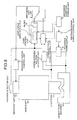
- Fig. 1 is a block diagram showing the configuration of an electric discharge machining device according to a first embodiment of the present invention
- Fig. 2 is a graph showing an example of a command locus generated by a jump locus generation unit of the electric discharge machining device according to the first embodiment of the present invention
- Fig. 3 is a graph showing an example of a command locus generated by a jump locus generation unit of an electric discharge machining device according to a second embodiment of the present invention
- Fig. 4 is a block diagram showing the configuration of an electric discharge machining device according to a third embodiment of the present invention
- Fig. 1 is a block diagram showing the configuration of an electric discharge machining device according to a first embodiment of the present invention
- Fig. 2 is a graph showing an example of a command locus generated by a jump locus generation unit of the electric discharge machining device according to the first embodiment of the present invention
- Fig. 3 is a graph showing an example of a command locus generated by a jump locus generation unit of an
- FIG. 5 is a graph showing an example of a command locus generated by a jump locus generation unit of an electric discharge machining device according to a fourth embodiment of the present invention
- Fig. 6 is a graph showing a Fourier transform result shown in Fig. 5
- Fig. 7 is a graph showing an example of a Fourier transform result to a command locus generated by a jump locus generation unit of an electric discharge machining device according to a fifth embodiment of the present invention
- Fig. 8 is a block diagram showing the configuration of an electric discharge machining device according to a sixth embodiment of the present invention
- Fig. 9 is a graph showing an example of a command locus generated by a jump locus generation unit of an electric discharge machining device according to a seventh embodiment of the present invention
- Fig. 10 is a graph showing an example of a command locus which is a modification of the seventh embodiment of the present invention
- Fig. 11 is a block diagram showing the configuration of an electric discharge machining device according to a eighth embodiment of the present invention
- Fig. 12 is a graph showing an example of a command locus generated by a jump locus generation unit which is a ninth embodiment of the present invention
- Fig. 13 is a graph showing an example of a decomposition waveform of a partial waveform in Fig. 12
- Fig. 14 is a block diagram showing the configuration of a conventional electric discharge machining device
- Fig. 15 is a graph for explaining a jump operation performed by the conventional electric discharge machining device.
- Fig. 1 shows a block diagram of the configuration of an electric discharge machining device according to the first embodiment of the present invention.
- a machining power supply control unit 5 controls a machining power supply 10 on the basis of information stored in a machining condition storage unit 4 and related to machining power supply control to apply a voltage across an electrode 11 and an object 12.
- An interelectrode servo control unit 3 controls an interelectrode distance between an interelectrode voltage detection result of an interelectrode voltage detection unit 7 for detecting an interelectrode voltage between the electrode 11 and the object 12 and a position detection result of the electrode 11 obtained by a position detection unit 8.
- the interelectrode servo control unit 3 controls a main shaft motor control unit 6, drives a main shaft motor 9 on the basis of this control, and vertically moves the position of a main shaft 13 to move the electrode 11. As a result, an interelectrode distance between the electrode 11 and the object 12 is controlled.
- the interelectrode servo control unit 3 performs control on the basis of a servo control condition stored in the machining condition storage unit 4.
- a jump control unit 2 controls a jump operation for temporarily largely jumping the interelectrode distance every predetermined time or depending on a machining state on the basis of jump operation condition information stored in the machining condition storage unit 4.
- the jump control unit 2 controls the interelectrode distance between the electrode 11 and the object 12 through the main shaft motor control unit 6, the main shaft motor 9 and the main shaft 13 like the control of the interelectrode distance by the interelectrode servo control unit 3.
- the jump control unit 2 controls the interelectrode distance on the basis of a position detection result of the position detection unit 8 for detecting the position of the electrode 11.
- Switching between the control by the interelectrode servo control unit 3 and the control by the jump control unit 2 is performed by a switching unit SW.
- the jump control unit 2 When the jump control unit 2 performs a jump operation, the jump control unit 2 notifies the interelectrode servo control unit 3 that the jump operation is performed, and controls the switching unit SW to switch the control from the interelectrode servo control unit 3 to the jump control unit 2.
- the jump control unit 2 has a jump locus generation unit 1.
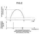
- the jump locus generation unit 1 generates a command locus of an interelectrode distance shown in Fig. 2(a) on the basis of jump operation condition information stored in the machining condition storage unit 4, and the jump control unit 2 controls the jump operation on the basis of the command locus.
- Fig. 2(b) shows a Fourier transform result of the command locus shown in Fig. 2(a).
- a locus generated by a sine wave of a low frequency f which is lower than a reference frequency fc is used.
- f1 represents a frequency component of a command locus.
- "11” represents an interelectrode distance at a jump operation start point t1 and a jump operation end point t2
- "12" represents the maximum value of an interelectrode distance in the jump operation.
- the reference frequency fc a resonance frequency of an electric discharge machining device (mechanical system) is used.
- the equation of the interelectrode distance L(t) is stored in the machining condition storage unit 4.
- the jump locus generation unit 1 generates a command locus from the machining condition storage unit 4 on the basis of the equation of the interelectrode distance L(t), and the jump control unit 2 controls a jump operation on the basis of the command locus.
- the jump locus generation unit 1 since the jump locus generation unit 1 generates a smooth command locus obtained by a sine wave of only a component of a frequency f1 which is lower than the resonance frequency fc, vibration in a mechanical system does not remain upon completion of the jump operation, and precise machining can be performed.
- the command locus is generated by a sine wave of only a component of one frequency f1 which is lower than the reference frequency fc.
- the frequency f1 may be equal to or lower than the reference frequency fc, and a command locus including at least two frequency components which are lower than the reference frequency fc may be generated.
- a resonance frequency of the mechanical system is used as the reference frequency fc.
- a cut-off frequency calculated by frequency response of a control system, 1/2 of a sampling frequency of a digital controller, or a reference frequency for setting these frequencies, e.g., a frequency which is A times (0 ⁇ A ⁇ 1) of the cut-off frequency may be used.
- a jump operation is performed such that a command locus, i.e., the position of the interelectrode distance is controlled.
- the interelectrode distance may be controlled by speed control or acceleration control.
- a second embodiment of the present invention will be described below.
- the configuration of an electric discharge machining device according to this second embodiment is same as that of the electric discharge machining device shown in Fig. 1 except for an equation of an interelectrode distance "L(t)" stored by a machining condition storage unit 4 and a generation process of a command locus performed by a jump locus generation unit 1.
- Fig. 3 is a graph showing a command locus of a jump operation generated by the jump locus generation unit 1 of the electric discharge machining device according to the second embodiment of the present invention and a Fourier transform result of the command locus.
- the command locus of the jump operation shown in Fig. 3 is generated by a sine wave having a frequency component except for frequencies ranging from a frequency which is 0.9 times an reference frequency fc to a frequency which is 1.1 times the reference frequency fc.
- "f2" represents a frequency component of a command locus.
- "11” represents an interelectrode distance at a jump operation start point t1 and a jump operation end point t2, and "12” represents the maximum value of an interelectrode distance in the jump operation.
- the reference frequency fc a resonance frequency of an electric discharge machining device (mechanical system) is used.
- the equation of the interelectrode distance L(t) is stored in the machining condition storage unit 4.
- the jump locus generation unit 1 generates a command locus from the machining condition storage unit 4 on the basis of the equation of the interelectrode distance L(t), and the jump control unit 2 controls a jump operation on the basis of the command locus.
- the jump locus generation unit 1 since the jump locus generation unit 1 generates a smooth command locus obtained by a sine wave of only a component of a frequency f2 except for frequencies ranging from a frequency which is 0.9 times the resonance frequency fc to a frequency which is 1.1 times the resonance frequency fc, a frequency f2 which is sufficiently different from the resonance frequency fc, vibration in a mechanical system does not remain upon completion of the jump operation, and precise machining can be performed.
- the command locus is generated by a sine wave having only one frequency f2 except for frequencies ranging from the frequency which is 0.9 times the reference frequency fc to the frequency which is 1.1 times the reference frequency fc.
- a command locus including at least two frequency components which satisfy the condition may be generated.
- the command locus is generated by only the frequency except for frequencies ranging from the frequency which is 0.9 times the reference frequency fc to the frequency which is 1.1 times the reference frequency fc.
- the command locus may be generated by only a frequency except for frequencies ranging from the frequency which is A times (0 ⁇ A ⁇ 1) the reference frequency fc to the frequency which is B times (1 ⁇ B) the reference frequency fc.
- the resonance frequency of the mechanical system is used as the reference frequency fc
- a cut-off frequency calculated by response of a control system or 1/2 of a sampling frequency of a digital controller may be used.
- the jump operation is performed such that a command locus, i.e., the position of the interelectrode distance is controlled.
- the interelectrode distance may be controlled by speed control or acceleration control.
- a third embodiment of the present invention will be described below.
- a configuration obtained by adding a machining condition input unit 14 to the electric discharge machining device shown in Fig. 1 is employed.
- Fig. 4 is a block diagram showing the configuration of an electric discharge machining device according to the third embodiment of the present invention.
- the machining condition input unit 14 input jump operation condition information, i.e., parameters used in locus generation for a jump operation to a machining condition storage unit 4.
- the reference frequency fc and the conditions such as "f ⁇ fc" are set and input.
- a fourth embodiment of the present invention will be described below.
- the configuration of an electric discharge machining device according to the fourth embodiment is different from that of the electric discharge machining device shown in Fig. 1 in the equation of an interelectrode distance L (t) stored in a machining condition storage unit 4 and a generation process of a command locus performed by a jump locus generation unit 1, and the other configuration is the same as that of the electric discharge machining device shown in Fig. 1.
- Fig. 5 is a graph showing a command locus of a jump operation generated by a jump locus generation unit of the electric discharge machining device according to the fourth embodiment of the present invention.
- Fig. 6 is a graph showing a Fourier transform result of the command locus shown in Fig. 5.
- the command locus shown in Fig. 5 is a locus which shapes an almost crest from a point of time t1 to a point of time t4. However, a distance from an interelectrode distance 13 at the point of time t4 to an interelectrode distance 11 at a point of time t3 upon completion of the jump operation is set as a deceleration distance (l3 - l1).
- a frequency component value in a frequency range which is equal to or higher than the reference frequency (resonance frequency) fc is suppressed to a value which is equal to or smaller than a predetermined value C.
- the deceleration distance (l3 - l1) can be shortened to reduce the vibration and to reduce an amount of overshooting.
- time required for the entire jump operation (t3 - t1) can be shortened, and machining speed can be increased.
- the resonance frequency of the mechanical system is used as the reference frequency fc.
- a cut-off frequency calculated by frequency response of a control system, 1/2 of a sampling frequency of a digital controller, or a reference frequency for setting these frequencies, e.g., a frequency which is A times (0 ⁇ A ⁇ 1) of the cut-off frequency may be used.
- a jump operation is performed such that a command locus, i.e., the position of the interelectrode distance is controlled.
- the interelectrode distance may be controlled by speed control or acceleration control.
- a fifth embodiment of the present invention will be described below.
- the command locus in which the frequency component value in the frequency range which is equal to or higher than the resonance frequency fc is equal to or smaller than the predetermined value C is generated.
- a frequency component value in a frequency range from the frequency which is 0.9 times the resonance frequency fc to the frequency which is 1.1 times the resonance frequency fc is set to be equal to or smaller than the predetermined value C.
- Fig. 7 is, for example, a graph showing an example of a Fourier transform result of a command locus which is approximate to that in Fig. 5.
- a frequency component value in a frequency range froma frequency (0.9 fc) which is 0.9 times a resonance frequency fc to a frequency (1.1 ⁇ fc) which is 1.1 times the resonance frequency fc is set to be equal to or smaller than a predetermined value C.
- the resonance frequency of the mechanical system is used as the reference frequency fc.
- a cut-off frequency calculated by frequency response of a control system, 1/2 of a sampling frequency of a digital controller, or a reference frequency for setting these frequencies, e.g., a frequency which is A times (0 ⁇ A ⁇ 1) of the cut-off frequency may be used.
- the command locus of the jump operation in which the frequency component value in the frequency range from the frequency which is 0.9 times the resonance frequency to the frequency which is 1.1 times the resonance frequency is suppressed to a value which is equal to or smaller than the predetermined value C is generated.
- the frequency component value in a frequency range from a frequency which is A times (0 ⁇ A ⁇ 1) the resonance frequency fc to a frequency which is B times (1 ⁇ B) the resonance frequency fc may be suppressed to a value which is equal to or smaller than the predetermined value C.
- the jump operation is performed such that the command locus, i.e., the position of the interelectrode distance is controlled.
- the interelectrode distance may be controlled by speed control or acceleration control.
- the jump generation units 1 generate the command loci in which the frequency component values in the frequency ranges are suppressed to the value which is equal to or smaller than the predetermined value C.
- a filter 15 which suppresses the frequency component value in the frequency range which is equal to or higher than the resonance frequency fc to a value which is equal to or larger than the predetermined value C.
- Fig. 8 is a block diagram showing the configuration of an electric discharge machining device according to the sixth embodiment of the present invention.
- the filter 15 is an analog filter outputs a frequency component value in a frequency range which is equal to or higher than the resonance frequency fc such that the frequency component value is suppressed to a value which is equal to or smaller than the predetermined value C.
- the other configuration is the same as the configuration of the electric discharge machining device shown in Fig. 1.
- the filter 15 realized by an analog filter is arranged on the output stage of the jump control unit 2, so that the frequency component value in the frequency range which is equal to or higher than the resonance frequency fc is suppressed to the value which is equal to or smaller than the predetermined value C. For this reason, vibration of a mechanical system does not remain upon completion of a jump operation, and precise machining can be performed. In addition, since vibration is small, or since an amount of overshooting is small, a deceleration distance (l3 - l1) can be shortened. Entire jump operation time (t3 - t1) can be shortened, and machining speed can be increased.
- the frequency component value in the frequency range which is equal to or higher than the resonance frequency fc is suppressed to the value which is equal to or smaller than the predetermined value C.
- a digital filter may be incorporated in the jump locus generation unit 1 to generate a smooth command locus in which a frequency component value in a frequency range which is equal to or higher than the resonance frequency fc is suppressed to a value which is equal to or smaller than the predetermined value C.
- the jump operation is performed such that a command locus, i.e., the position of the interelectrode distance is controlled.
- the interelectrode distance may be controlled by speed control or acceleration control.
- one command locus is generated by using a plurality of loci.
- Fig. 9 is a graph for explaining an example of a command locus generation process of a jump operation performed by a jump locus generation unit 1 of an electric discharge machining device according to the seventh embodiment of the present invention.
- the sine wave L1(t) is a sine wave having a frequency component which is lower than a set frequency, i.e., a resonance frequency fc. Therefore, in the sine wave L1(t), a frequency component value in the frequency range which is equal to or higher than the resonance frequency fc is 0.
- L2(t) 0 (t ⁇ t1) D (t1 ⁇ t ⁇ t3) 0 (t3 ⁇ t).
- This rectangular wave L2(t) is subjected to Fourier series development, the following equation can be obtained: ⁇ sin(2(2m + 1) ⁇ /(t3 - t1))(t - t1)).
- the size of a frequency component value of a frequency f[Hz] is calculated, the following value is obtained: 4D/ ⁇ f(t3 - t1).
- a value "D" is sufficiently decreased such that the frequency component value of the resonance frequency fc is equal to or smaller than the predetermined value C, or a time value (t3 - t1) is increased, so that the frequency component value in an entire frequency range in which the frequency f is equal to or higher than the resonance frequency fc is equal to or smaller than the predetermined value C.
- the command locus L(t) of the jump operation is a function of these values, i.e., the sum of the sine wave L1(t) and the rectangular wave L2(t). For this reason, the frequency component value in the frequency range which is higher than the resonance frequency fc can be set to be equal to or smaller than the predetermined value C.
- a command locus of a jump operation in which the sum of the frequency component values in the frequency range which is higher than the resonance frequency fc is equal to or smaller than the predetermined value C is generated. For this reason, upon completion of the jump operation, vibration of a mechanical system does not remain, and precise machining can be performed.
- the command locus L(t) is generated by the sum of the sine wave L1(t) and the rectangular wave L2(t).
- two or more sine waves L1(t) and two or more rectangular waves L2(t) may be added.
- two or more sine waves L1(t) or two or more rectangular waves L2(t) may be added to generate a command locus L(t).
- a function of another locus i.e., a chopping wave may be added to generate a command locus.
- the command locus is calculated as the sum of only functions defined in an entire time range from a jump operation start point t1 to a jump operation end point t3.
- the time range is divided, and command loci are generated for the respective time ranges, so that a locus obtained by connecting these time ranges may be obtained as the command locus.
- the time range may be divided into a more large number of time ranges. For example,
- the jump operation is performed such that a command locus, i.e., the position of the interelectrode distance is controlled.
- the interelectrode distance may be controlled by speed control or acceleration control.
- a jump control unit 2 evaluates an operation state of a jump operation, and a command locus is automatically set again such that an appropriate jump operation is performed on the basis of the evaluation result.
- Fig. 11 is a block diagram showing the configuration of an electric discharge machining device according to the eighth embodiment of the present invention.
- This electric discharge machining device is different from the electric discharge machining device shown in Fig. 1 in the configuration of the jump control unit 2, and the other configuration of the electric discharge machining device in Fig. 11 is the same as that of the electric discharge machining device shown in Fig. 1.
- the jump control unit 2 has an evaluation unit 21 and a setting change unit 22.
- the evaluation unit 21 to cause a jump locus generation unit 1 to generate a command locus based on jump operation condition information stored in the machining condition storage unit 4, and a jump operation is executed on the basis of the command locus.
- the evaluation unit 21 instructs the setting change unit 22 to set a command locus for decreasing a resonance frequency fc or decreasing an allowable vibration amount (predetermined value C).
- the setting change unit 22 stores this instruction in the machining condition storage unit 4. More specifically, the setting of the jump operation condition information in the machining condition storage unit 4 is automatically changed. By the setting change, a jump operation is executed by a command locus using the jump operation condition information which is subjected to setting change, i.e., which is corrected in the next jump operation.
- an actual motion of a main shaft 13 is evaluated, and settings of the conditions such as a resonance frequency fc and the allowable vibration amount (predetermined value C) are changed. For this reason, machining conditions are automatically optimized, and machining can be performed at a high speed and a high precision.
- the command locus of the jump operation which is subjected to setting change in the jump operation next to the jump operation evaluated by the evaluation unit 21 is applied.
- the command locus which is subjected to the setting change may be applied from the second or subsequent jump operation.
- an acceleration locus in consideration of frequency component values of functions of accelerations, is subjected to second-order integration such that the sum of frequency component values in a frequency range which is higher than a resonance frequency fc is equal to or smaller than a predetermined value C, so that a command locus is generated.
- Fig. 12 is a graph showing an example of a generation process of a command locus generated by a jump locus generation unit 1 of an electric discharge machining device according to the ninth embodiment of the present invention.
- an acceleration locus is determined. More specifically, in respective sections between a point of time TA1 and a point of time TA16, the following acceleration loci are determined.
- the waveform of the acceleration locus in the section represented by TA1 ⁇ t ⁇ TA4 includes a rectangular wave indicated by a solid line in Fig. 13.
- This rectangular wave is the sum of two rectangular waves defined by: height: a1/2, width: TA4 - TA1 and height: a1/2, width: TA3 - TA2.
- a value "a1" is decreased, or a time interval is lengthened such that a frequency component value expressed by: 2a1/ ⁇ f(TA4 - TA1) + 2a1/ ⁇ f(TA3 - TA2) at the frequency f is equal to or smaller than the predetermined value C.
- frequency components at the frequency f are set to be equal to or smaller than the predetermined value C, and an acceleration function is determined such that a maximum interelectrode distance 12, a maximum speed V1, a deceleration distance 12, a speed - V2 in a deceleration distance reach state satisfy conditions, respectively.
- a speed locus in Fig. 12 (b) obtained by performing first-order integration to an acceleration locus shown in Fig. 12 (a) is calculated, and a command locus shown in Fig. 12(c) obtained by further integrating the speed locus shown in Fig. 12(b), i.e., by performing second-order integration to the acceleration locus in Fig. 12(a) is finally calculated.
- the acceleration locus in consideration of the frequency components of respective functions of an acceleration, the acceleration locus is subjected to second-order integration such that the sum of frequency component values in a frequency range which is higher than the resonance frequency fc is equal to or smaller than the predetermined value C, so that a command locus is generated. For this reason, vibration of a mechanical system does not remain upon completion of the jump operation, and precise machining can be performed. Since vibration is small, and since an amount of overshooting is small, a deceleration distance (l3 - l1) can be shortened. Entire jump operation time (t3 - t1) can be shortened, and machining speed can be increased.
- the command locus of the jump operation is generated such that the acceleration locus satisfies the condition, and the acceleration locus is subjected to second-order integration to calculate a command value an interelectrode distance, i.e., a command locus.
- the jump control unit 2 may perform speed control or acceleration control based on the speed locus or the acceleration locus in place of the command locus.
- a second-order integration process is performed in generation of the command locus.
- a first-order or a third-or-higher-order integration process may be performed.
- a first-or-higher-order differential process may be performed to calculate a desired command locus, a speed locus, and an acceleration locus.
- This invention can be used in an electric discharge machining device and an electric discharge machining method which a voltage is applied across an electrode and an object to machine the object by using an electric discharge phenomenon generated between both the electrodes and, more particularly, is preferably applied to an electric discharge machining device and an electric discharge machining method for controlling a jump operation for temporarily increasing an interelectrode distance every predetermined time or depending on a machining state.
Landscapes
- Engineering & Computer Science (AREA)
- Mechanical Engineering (AREA)
- Chemical & Material Sciences (AREA)
- Chemical Kinetics & Catalysis (AREA)
- Electrochemistry (AREA)
- Electrical Discharge Machining, Electrochemical Machining, And Combined Machining (AREA)
Applications Claiming Priority (1)
| Application Number | Priority Date | Filing Date | Title |
|---|---|---|---|
| PCT/JP2000/003097 WO2001087527A1 (en) | 2000-05-15 | 2000-05-15 | Electric discharge machine and method of electric discharge machining |
Publications (3)
| Publication Number | Publication Date |
|---|---|
| EP1283084A1 true EP1283084A1 (de) | 2003-02-12 |
| EP1283084A4 EP1283084A4 (de) | 2007-11-28 |
| EP1283084B1 EP1283084B1 (de) | 2011-07-06 |
Family
ID=11736028
Family Applications (1)
| Application Number | Title | Priority Date | Filing Date |
|---|---|---|---|
| EP00927768A Expired - Lifetime EP1283084B1 (de) | 2000-05-15 | 2000-05-15 | Funkenerosionsmaschine und funkenerosionsbearbeitungsverfahren |
Country Status (5)
| Country | Link |
|---|---|
| US (1) | US6608275B1 (de) |
| EP (1) | EP1283084B1 (de) |
| JP (1) | JP4260397B2 (de) |
| KR (1) | KR100450806B1 (de) |
| WO (1) | WO2001087527A1 (de) |
Cited By (1)
| Publication number | Priority date | Publication date | Assignee | Title |
|---|---|---|---|---|
| CN100439577C (zh) * | 2003-09-02 | 2008-12-03 | 倪远 | 纤维打击梳理元件锐化和强化的方法与装置 |
Families Citing this family (3)
| Publication number | Priority date | Publication date | Assignee | Title |
|---|---|---|---|---|
| KR100537769B1 (ko) * | 2001-01-09 | 2005-12-19 | 미쓰비시덴키 가부시키가이샤 | 방전가공장치 |
| AU2003218101A1 (en) * | 2002-03-13 | 2003-09-29 | Georgia Tech Research Corporation | Shaping and smooth baseline function command generator |
| US6979795B1 (en) | 2005-03-18 | 2005-12-27 | Sodick Co., Ltd. | Sinker electric discharge machine jump control device |
Family Cites Families (11)
| Publication number | Priority date | Publication date | Assignee | Title |
|---|---|---|---|---|
| DE3644042A1 (de) * | 1986-12-22 | 1988-06-30 | Agie Ag Ind Elektronik | Verfahren und vorrichtung zum spuelen der erodierzone beim elektroerosiven senken |
| JP2807046B2 (ja) | 1990-05-29 | 1998-09-30 | 昭和電工株式会社 | 光ファイバー |
| JP2692022B2 (ja) | 1991-10-28 | 1997-12-17 | 三菱電機株式会社 | 放電加工装置 |
| JPH06126534A (ja) * | 1992-10-21 | 1994-05-10 | Mitsubishi Electric Corp | 放電加工装置 |
| JPH06250723A (ja) * | 1993-02-25 | 1994-09-09 | Komatsu Ltd | ロボットの振動低減装置 |
| JPH0724638A (ja) | 1993-07-15 | 1995-01-27 | Okuma Mach Works Ltd | 放電加工制御装置 |
| JP3056928B2 (ja) | 1993-10-28 | 2000-06-26 | オークマ株式会社 | 放電加工機の主軸負荷力軽減装置 |
| JP3575087B2 (ja) * | 1994-12-07 | 2004-10-06 | 三菱電機株式会社 | 放電加工装置 |
| JPH10296538A (ja) * | 1997-04-24 | 1998-11-10 | Mitsubishi Electric Corp | 放電加工装置 |
| JP3842377B2 (ja) * | 1997-05-09 | 2006-11-08 | 株式会社ソディック | 放電加工制御方法及びその装置 |
| JP3841569B2 (ja) * | 1998-09-14 | 2006-11-01 | 株式会社牧野フライス製作所 | 放電加工機のジャンプ動作制御方法および装置 |
-
2000
- 2000-05-15 KR KR10-2002-7000515A patent/KR100450806B1/ko not_active Expired - Fee Related
- 2000-05-15 JP JP2001583971A patent/JP4260397B2/ja not_active Expired - Fee Related
- 2000-05-15 EP EP00927768A patent/EP1283084B1/de not_active Expired - Lifetime
- 2000-05-15 US US09/937,384 patent/US6608275B1/en not_active Expired - Lifetime
- 2000-05-15 WO PCT/JP2000/003097 patent/WO2001087527A1/ja not_active Ceased
Cited By (1)
| Publication number | Priority date | Publication date | Assignee | Title |
|---|---|---|---|---|
| CN100439577C (zh) * | 2003-09-02 | 2008-12-03 | 倪远 | 纤维打击梳理元件锐化和强化的方法与装置 |
Also Published As
| Publication number | Publication date |
|---|---|
| EP1283084A4 (de) | 2007-11-28 |
| US6608275B1 (en) | 2003-08-19 |
| WO2001087527A1 (en) | 2001-11-22 |
| EP1283084B1 (de) | 2011-07-06 |
| JP4260397B2 (ja) | 2009-04-30 |
| KR20020019520A (ko) | 2002-03-12 |
| KR100450806B1 (ko) | 2004-10-01 |
Similar Documents
| Publication | Publication Date | Title |
|---|---|---|
| US7670015B2 (en) | Optical switch controller and movable body controller | |
| JP5230110B2 (ja) | 可変空隙距離を有するエネルギ変換システム及びエネルギ回生システム | |
| US10693394B2 (en) | Driving apparatus of vibration-type actuator method of controlling driving vibration-type actuator and image pickup apparatus | |
| US5539268A (en) | Vibration type actuator device | |
| CN112384882B (zh) | 致动器控制装置和方法 | |
| JP6105650B2 (ja) | 機械の負荷を低減する数値制御装置 | |
| JPWO2011089648A1 (ja) | 数値制御装置、これを用いたワイヤ放電加工装置、及びこれを用いたワイヤ放電加工方法 | |
| EP1283084A1 (de) | Funkenerosionsmaschine und funkenerosionsbearbeitungsverfahren | |
| US10118818B2 (en) | Controller for actuating a micromechanical actuator, actuating system for actuating a micromechanical actuator, micro-mirror system and method for actuating a micromechanical actuator | |
| CN108429405A (zh) | 线性电机共振频率的检测方法及装置 | |
| JPWO2001087527A1 (ja) | 放電加工装置および放電加工方法 | |
| JP3609927B2 (ja) | 駆動装置 | |
| US9310606B2 (en) | Controller for actuating a micromechanical actuator, actuating system for actuating a micromechanical actuator, micro-mirror system and method for actuating a micromechanical actuator | |
| JPH11356071A (ja) | 電気機械変換素子を用いた駆動装置およびその駆動回路 | |
| US7697829B1 (en) | Electronic damping for stage positioning | |
| US20110018475A1 (en) | Ultrasonic motor | |
| CN110213702B (zh) | 用于操作压电扬声器的方法及电路 | |
| KR20180113197A (ko) | 전기 기계 소자를 액추에이팅하는 방법 및 장치 | |
| JP2012023917A (ja) | 駆動装置 | |
| JP3739473B2 (ja) | ワイヤ放電加工機の制御装置 | |
| JP2022029016A (ja) | 振動型モータの制御装置 | |
| RU2071106C1 (ru) | Оптимальная система позиционирования | |
| SU1581506A1 (ru) | Устройство дл цифрового регулировани параметра сварки | |
| CN120113146A (zh) | 马达驱动装置以及马达驱动方法 | |
| CN119043661A (zh) | 基于sogi-fll的电机驱动机械震荡实时检测方法及系统 |
Legal Events
| Date | Code | Title | Description |
|---|---|---|---|
| PUAI | Public reference made under article 153(3) epc to a published international application that has entered the european phase |
Free format text: ORIGINAL CODE: 0009012 |
|
| 17P | Request for examination filed |
Effective date: 20011203 |
|
| AK | Designated contracting states |
Designated state(s): AT BE CH CY DE DK ES FI FR GB GR IE IT LI LU MC NL PT SE |
|
| AX | Request for extension of the european patent |
Extension state: AL LT LV MK RO SI |
|
| RBV | Designated contracting states (corrected) |
Designated state(s): CH DE LI |
|
| RAP1 | Party data changed (applicant data changed or rights of an application transferred) |
Owner name: MITSUBISHI DENKI KABUSHIKI KAISHA |
|
| A4 | Supplementary search report drawn up and despatched |
Effective date: 20071031 |
|
| 17Q | First examination report despatched |
Effective date: 20080528 |
|
| GRAP | Despatch of communication of intention to grant a patent |
Free format text: ORIGINAL CODE: EPIDOSNIGR1 |
|
| RTI1 | Title (correction) |
Free format text: ELECTRIC DISCHARGE MACHINING DEVICE AND ELECTRIC DISCHARGE MACHINING METHOD |
|
| GRAS | Grant fee paid |
Free format text: ORIGINAL CODE: EPIDOSNIGR3 |
|
| RIN1 | Information on inventor provided before grant (corrected) |
Inventor name: IMAI, YOSHIHITOMITSUBISHI DENKI KABUSHIKI KAISHA Inventor name: NAKAGAWA, TAKAYUKIMITSUBISHI DENKI KABUSHIKI KAISH |
|
| GRAA | (expected) grant |
Free format text: ORIGINAL CODE: 0009210 |
|
| AK | Designated contracting states |
Kind code of ref document: B1 Designated state(s): CH DE LI |
|
| REG | Reference to a national code |
Ref country code: CH Ref legal event code: EP |
|
| REG | Reference to a national code |
Ref country code: DE Ref legal event code: R096 Ref document number: 60046176 Country of ref document: DE Effective date: 20110825 |
|
| PLBE | No opposition filed within time limit |
Free format text: ORIGINAL CODE: 0009261 |
|
| STAA | Information on the status of an ep patent application or granted ep patent |
Free format text: STATUS: NO OPPOSITION FILED WITHIN TIME LIMIT |
|
| 26N | No opposition filed |
Effective date: 20120411 |
|
| REG | Reference to a national code |
Ref country code: DE Ref legal event code: R097 Ref document number: 60046176 Country of ref document: DE Effective date: 20120411 |
|
| REG | Reference to a national code |
Ref country code: CH Ref legal event code: PL |
|
| PG25 | Lapsed in a contracting state [announced via postgrant information from national office to epo] |
Ref country code: CH Free format text: LAPSE BECAUSE OF NON-PAYMENT OF DUE FEES Effective date: 20120531 Ref country code: LI Free format text: LAPSE BECAUSE OF NON-PAYMENT OF DUE FEES Effective date: 20120531 |
|
| PGFP | Annual fee paid to national office [announced via postgrant information from national office to epo] |
Ref country code: DE Payment date: 20160510 Year of fee payment: 17 |
|
| REG | Reference to a national code |
Ref country code: DE Ref legal event code: R119 Ref document number: 60046176 Country of ref document: DE |
|
| PG25 | Lapsed in a contracting state [announced via postgrant information from national office to epo] |
Ref country code: DE Free format text: LAPSE BECAUSE OF NON-PAYMENT OF DUE FEES Effective date: 20171201 |