EP1282793B1 - Method for manufacturing an elastic sealing ring and sealing ring manufactured according to the method - Google Patents
Method for manufacturing an elastic sealing ring and sealing ring manufactured according to the method Download PDFInfo
- Publication number
- EP1282793B1 EP1282793B1 EP01932483A EP01932483A EP1282793B1 EP 1282793 B1 EP1282793 B1 EP 1282793B1 EP 01932483 A EP01932483 A EP 01932483A EP 01932483 A EP01932483 A EP 01932483A EP 1282793 B1 EP1282793 B1 EP 1282793B1
- Authority
- EP
- European Patent Office
- Prior art keywords
- sealing ring
- sealing
- piston rod
- component
- shaped
- Prior art date
- Legal status (The legal status is an assumption and is not a legal conclusion. Google has not performed a legal analysis and makes no representation as to the accuracy of the status listed.)
- Expired - Lifetime
Links
- 238000007789 sealing Methods 0.000 title claims abstract description 84
- 238000000034 method Methods 0.000 title claims abstract description 14
- 238000004519 manufacturing process Methods 0.000 title claims abstract description 8
- 239000000463 material Substances 0.000 claims abstract description 82
- 238000002347 injection Methods 0.000 claims description 3
- 239000007924 injection Substances 0.000 claims description 3
- 230000002093 peripheral effect Effects 0.000 claims description 2
- 238000000465 moulding Methods 0.000 claims 1
- 239000011162 core material Substances 0.000 description 18
- 238000001125 extrusion Methods 0.000 description 13
- 238000010438 heat treatment Methods 0.000 description 13
- 229920002635 polyurethane Polymers 0.000 description 7
- 239000004814 polyurethane Substances 0.000 description 7
- 239000004033 plastic Substances 0.000 description 6
- 229920003023 plastic Polymers 0.000 description 6
- 235000019589 hardness Nutrition 0.000 description 4
- 239000010720 hydraulic oil Substances 0.000 description 3
- 239000002184 metal Substances 0.000 description 3
- 230000001627 detrimental effect Effects 0.000 description 2
- 239000012535 impurity Substances 0.000 description 2
- 238000001746 injection moulding Methods 0.000 description 2
- 238000012423 maintenance Methods 0.000 description 2
- 239000004809 Teflon Substances 0.000 description 1
- 229920006362 Teflon® Polymers 0.000 description 1
- 239000003638 chemical reducing agent Substances 0.000 description 1
- 239000013013 elastic material Substances 0.000 description 1
- 229920001971 elastomer Polymers 0.000 description 1
- 239000000806 elastomer Substances 0.000 description 1
- 239000012530 fluid Substances 0.000 description 1
- 238000012986 modification Methods 0.000 description 1
- 230000004048 modification Effects 0.000 description 1
- 238000012856 packing Methods 0.000 description 1
- 230000000149 penetrating effect Effects 0.000 description 1
- 239000000843 powder Substances 0.000 description 1
- 230000000717 retained effect Effects 0.000 description 1
- 239000007779 soft material Substances 0.000 description 1
Images


Classifications
-
- B—PERFORMING OPERATIONS; TRANSPORTING
- B29—WORKING OF PLASTICS; WORKING OF SUBSTANCES IN A PLASTIC STATE IN GENERAL
- B29C—SHAPING OR JOINING OF PLASTICS; SHAPING OF MATERIAL IN A PLASTIC STATE, NOT OTHERWISE PROVIDED FOR; AFTER-TREATMENT OF THE SHAPED PRODUCTS, e.g. REPAIRING
- B29C45/00—Injection moulding, i.e. forcing the required volume of moulding material through a nozzle into a closed mould; Apparatus therefor
- B29C45/16—Making multilayered or multicoloured articles
- B29C45/1642—Making multilayered or multicoloured articles having a "sandwich" structure
-
- F—MECHANICAL ENGINEERING; LIGHTING; HEATING; WEAPONS; BLASTING
- F16—ENGINEERING ELEMENTS AND UNITS; GENERAL MEASURES FOR PRODUCING AND MAINTAINING EFFECTIVE FUNCTIONING OF MACHINES OR INSTALLATIONS; THERMAL INSULATION IN GENERAL
- F16J—PISTONS; CYLINDERS; SEALINGS
- F16J15/00—Sealings
- F16J15/16—Sealings between relatively-moving surfaces
- F16J15/32—Sealings between relatively-moving surfaces with elastic sealings, e.g. O-rings
- F16J15/3204—Sealings between relatively-moving surfaces with elastic sealings, e.g. O-rings with at least one lip
- F16J15/3232—Sealings between relatively-moving surfaces with elastic sealings, e.g. O-rings with at least one lip having two or more lips
- F16J15/3236—Sealings between relatively-moving surfaces with elastic sealings, e.g. O-rings with at least one lip having two or more lips with at least one lip for each surface, e.g. U-cup packings
-
- F—MECHANICAL ENGINEERING; LIGHTING; HEATING; WEAPONS; BLASTING
- F16—ENGINEERING ELEMENTS AND UNITS; GENERAL MEASURES FOR PRODUCING AND MAINTAINING EFFECTIVE FUNCTIONING OF MACHINES OR INSTALLATIONS; THERMAL INSULATION IN GENERAL
- F16J—PISTONS; CYLINDERS; SEALINGS
- F16J15/00—Sealings
- F16J15/16—Sealings between relatively-moving surfaces
- F16J15/32—Sealings between relatively-moving surfaces with elastic sealings, e.g. O-rings
- F16J15/3284—Sealings between relatively-moving surfaces with elastic sealings, e.g. O-rings characterised by their structure; Selection of materials
-
- B—PERFORMING OPERATIONS; TRANSPORTING
- B29—WORKING OF PLASTICS; WORKING OF SUBSTANCES IN A PLASTIC STATE IN GENERAL
- B29L—INDEXING SCHEME ASSOCIATED WITH SUBCLASS B29C, RELATING TO PARTICULAR ARTICLES
- B29L2031/00—Other particular articles
- B29L2031/26—Sealing devices, e.g. packaging for pistons or pipe joints
Definitions
- the present invention relates to a method for manufacturing an elastic sealing ring for sealing between a displaceable and/or rotatable component, such as a piston, piston rod, shaft etc., and a surrounding component, such as a cylinder block, a cylinder end wall etc., which sealing ring is adapted so as to be mounted in a groove in one component and has at least one sealing surface intended for bearing against the other component.
- a displaceable and/or rotatable component such as a piston, piston rod, shaft etc.
- a surrounding component such as a cylinder block, a cylinder end wall etc.
- the invention also relates to an elastic sealing ring manufactured by means of the method according to the invention.
- Sealing rings of the type indicated above are used in many situations, inter alia as hydraulic seals for pistons and piston rods.
- One application is as a wiper for piston rods, their task being to prevent dirt or other impurities from, for example, accompanying a piston rod into a hydraulic cylinder. They can also be used on rotating shafts which may be, for example, axially displaceable.
- Another application is as a pressure seal between a piston rod and a cylinder end wall in order to prevent leakage of pressure fluid from the cylinder.
- a similar application is as a piston seal in order to bring about sealing between a displaceable piston and a surrounding cylinder block.
- Piston rod wipers and pressure seals for piston rods are commonly used together. Conventionally, however, they have been made and mounted as two separate components.
- an elastic sealing ring which is usually made of polyurethane, must be so soft/elastic that good sealing and bearing against the piston rod are obtained.
- a disadvantage of this is that the risk of gap extrusion, that is to say material being forced out into the gap between the two components which are to be sealed relative to one another, is relatively great.
- the entire seal body is also made of the same relatively elastic material, the friction against the piston rod increases, the temperature in the seal material then increasing, which in turn reduces the rigidity and brings about a further increase in. friction and temperature, and so forth.
- the sealing rings serving as wipers have commonly been provided with a sheet-metal surround in order to bring about secure mounting of the relatively elastic polyurethane ring in a groove in the surrounding block.
- One object of the present invention is to produce sealing rings for piston rods and pistons, in which inter alia the risk of detrimental friction heating and gap extrusion has been eliminated or greatly reduced.
- the invention is based on the knowledge (see for example EP 0 326 719) that this aim can be achieved by manufacturing a sealing ring by injection-molding two materials with different properties, so that a core made of a first material is obtained, which is surrounded by a thin layer of a second material with in part other properties.
- the inner material is to be sufficiently elastic in order to give the sealing ring the dynamic properties which are required for good flexibility and sealing action.
- This inner core material is surrounded by a thin layer of an outer material with low friction, which inter alia reduces friction heating of the seal material. Such heating otherwise reduces the rigidity of the seal material, which increases the risk of gap extrusion.
- the outer layer can be made of a harder material than the core.
- a material is injected which gives lower friction on contact with a component bearing against it than the first material, the second material preferably having a greater hardness than the first material.
- the materials can be injected into a mold which produces a dish-shaped blank, the peripheral outer edge portion of the blank being essentially V-shaped or U-shaped with two sealing lips for forming a pressure seal for a piston rod or the like, the sprue dish being cut away, so that the other end of the annular product obtained is shaped to form a piston rod wiper lip.
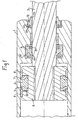
- reference number 1 designates a cylinder block and 2 a piston which is displaceable in the block and has a piston rod 3 projecting through the end wall of the block.
- the piston 2 is provided with an elastic sealing ring 6 made of an elastomer, suitably a polyurethane material, arranged in a groove 5.
- the polyurethane material must be relatively soft, which involves risks of gap extrusion, that is to say the risk that the seal material will be pressed into and crushed in the gap between the piston 2 and the surrounding cylinder block 1.
- the sealing ring 3 is supported on both sides by means of a pair of support rings 7 made of hard plastic material.
- Reference number 8 designates two guides for keeping the piston 2 centered in the cylinder.
- the piston seal therefore consists overall of a number of components which have to be manufactured and mounted separately, which increases costs.
- the relatively soft material in the sealing ring 6 also results in increased friction which inter alia increases friction heating etc. All in all, this increases the risk of the seal material being damaged on account of friction heating.
- Reference number 9 designates a so-called U packing ring which forms a pressure seal in order to prevent hydraulic oil from being pressed out from the cylinder along the piston rod 3.
- the pressure seal has two sealing lips 10 which will be pressed apart by the hydraulic pressure and then bring about good sealing of the piston rod 3. For this reason, the pressure seal 9 also has to be made of a relatively soft seal material with the attendant risk of detrimental friction heating. Furthermore, a support ring 11 is required in order to reduce the risk of gap extrusion as mentioned above.
- Reference number 12 relates to what is known as a piston rod wiper with an annular wiper lip 13 bearing against the piston rod 3. This prevents dirt and other impurities from accompanying the piston rod into the hydraulic cylinder.
- the wiper 12 also has to be manufactured from a relatively soft seal material.
- a sheet-metal surround 14 is usually embedded in the wiper, which can be pressed firmly into the groove 14 by means of a press fit.
- sealing rings for inter alia piston rod wipers, piston rod seals and piston seals are manufactured according to the present invention by double injection of two plastic materials with in part different properties. In this way, it is possible to produce sealing rings with an outer layer with relatively low friction in order inter alia to reduce friction heating and the risk of gap extrusion, and with a softer inner core which gives the sealing ring the necessary flexibility and adaptability so as to provide good sealing action.
- the outer layer is made of a harder material than the core.
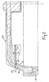
- Fig. 2 shows a section through one half of a dish-shaped blank, produced in a mold by double injection, for a piston rod wiper 16 according to the present invention.
- the blank has an inner core 17 made of a relatively elastic seal material, for example of polyurethane with a hardness of 40-70° Shore D, preferably roughly 50-60° Shore D.
- the core 17 is surrounded by a relatively thin outer layer 18 with a thickness of the order of 0.2-0.6 mm, preferably roughly 0.4 mm.
- the outer layer also suitably consists of a polyurethane material which, however, is harder than the material in the core 17 and has a hardness of the order of 85-95° Shore D, preferably roughly 90-93° Shore D. This harder outer layer results in low friction against the piston rod and thus low friction heating as well.
- the softer core 17 however, good flexibility and adaptability of the sealing ring are obtained for maintaining a good sealing function.
- the blank shown is manufactured by sequential injection-molding of the two plastic materials into a mold.
- the harder material which is to form the outer layer 18 of the sealing ring, is injected first.
- the material for the core 17 is injected centrally into the mold, this material, when injected, forcing the material injected first out against the delimiting surfaces of the mold cavity, so that the latter material will form an outer layer 18 which surrounds the softer material in the core 17.
- the wiper is to be provided with a sheet-metal surround 15, such a surround is positioned in the mold before the plastic materials are injected, so that it will be molded integral with the outer layer 18.
- the sprue dish 20 formed is cut off along an angled cutting line 21, so that a cut surface as illustrated in the figure is obtained.
- the outer layer 18 on the inner surface of the ring will then form a sealing lip 19 which bears against a piston rod which is guided through the sealing ring. This means that it is the harder material in the outer layer 18 which bears against the piston rod, which results in reduced friction and thus reduced friction heating in comparison with previously known wipers.
- the flexibility of the wiper lip 19 will be retained, however, on account of the softer material in the core 17 of the wiper ring.
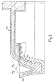
- Fig. 3 illustrates in a corresponding manner one half of a blank for a piston rod seal 22 after mold removal.
- the blank consists of a core 17 made of a soft plastic material, which is surrounded by an outer layer 18 made of a harder material.
- the sprue dish 20 is cut away, and the two end portions of the V-shaped sealing collar are chamfered along the lines 23 and 24. In this way, a sealing lip 25 with the cross section shown bearing against a piston rod guided through the collar, and a sealing lip 26 bearing against the bottom in a groove in a surrounding cylinder end wall are formed.
- Fig. 4 illustrates a blank for a combined piston rod wiper and piston rod seal.
- the blank is constructed from a relatively flexible core 17 and a harder outer layer 18.
- the sprue dish 20 is cut off along a cutting line 27 to form a piston rod wiper lip 28, as described above in connection with Fig. 2.
- the end portions of the blank are chamfered along the lines 29 and 30 to form sealing lips 31 and 32 for bearing against a surrounding cylinder block and, respectively, a piston rod.
- the part serving as the piston rod wiper is connected to the part serving as the piston rod seal via a relatively thin portion 33 which barely fills the gap present between the piston rod and the cylinder end wall.
- the risk is also eliminated of the seal material in the piston seal penetrating the gap between the piston and the cylinder end wall, which is also to a great extent filled by the material portion 33.
- FIG. 5 shows the application of sealing elements according to the invention in a hydraulic cylinder of the same type as is shown in Fig. 1.
- the reference numbers 1, 2 and 3 relate to a cylinder block, a piston and, respectively, a piston rod which projects through the cylinder block.
- the reference numbers 8 relate to guides for the piston 2 and the piston rod 3.
- a combined sealing element Arranged between the end wall of the cylinder block 1 and the piston rod 3 is a combined sealing element according to Fig. 4.
- This comprises a wiper lip 28 which bears against the piston rod 3, and a piston rod seal with a sealing lip 32 for bearing against the piston rod 3 and a sealing lip 31 for bearing against the bottom surface of a groove in the cylinder end wall.
- the sealing lips 31 and 32 are pressed away from one another on account of hydraulic oil entering the V-shaped space between these sealing lips.
- the sealing element according to the above is manufactured with a softer core and a harder outer layer, a sealing element is obtained with low friction and low friction heating but which still has the necessary flexibility for bringing about good sealing action.
- Manufacture and mounting are made easier and less costly, as it is necessary to handle only one element without a requirement for extra support rings or equivalent.
- the piston seal is made with a softer core 36 and a harder outer layer 37. This affords the same advantages as indicated in connection with the piston rod seal and means that no extra support rings for preventing gap extrusion are required. This means lower costs for the piston seal as well, as inter alia separate support rings do not have to be manufactured, mounted or maintained.
- sealing rings according to the invention can be made in undivided form, as the elasticity is sufficient for it to be possible for these to be pulled onto, for example, a piston or a piston rod.
- the support rings used previously had to be mounted in sections as they were too inelastic to be slipped onto, for example, a piston.
- the outer layer can consist of the same material as the core but with an addition of a friction-reducing substance, such as Teflon powder.
Landscapes
- Engineering & Computer Science (AREA)
- General Engineering & Computer Science (AREA)
- Mechanical Engineering (AREA)
- Manufacturing & Machinery (AREA)
- Sealing Devices (AREA)
- Pistons, Piston Rings, And Cylinders (AREA)
- Casting Or Compression Moulding Of Plastics Or The Like (AREA)
- Gasket Seals (AREA)
Applications Claiming Priority (3)
| Application Number | Priority Date | Filing Date | Title |
|---|---|---|---|
| SE0001874A SE0001874D0 (sv) | 2000-05-19 | 2000-05-19 | Sätt vid tillverkning av en elastisk tätningsring och en enligt sättet tillverkad tätningsring |
| SE0001874 | 2000-05-19 | ||
| PCT/SE2001/001113 WO2001090609A1 (en) | 2000-05-19 | 2001-05-18 | Method for manufacturing an elastic sealing ring and sealing ring manufactured according to the method |
Publications (2)
| Publication Number | Publication Date |
|---|---|
| EP1282793A1 EP1282793A1 (en) | 2003-02-12 |
| EP1282793B1 true EP1282793B1 (en) | 2005-12-28 |
Family
ID=20279757
Family Applications (1)
| Application Number | Title | Priority Date | Filing Date |
|---|---|---|---|
| EP01932483A Expired - Lifetime EP1282793B1 (en) | 2000-05-19 | 2001-05-18 | Method for manufacturing an elastic sealing ring and sealing ring manufactured according to the method |
Country Status (7)
| Country | Link |
|---|---|
| US (1) | US20030122317A1 (enExample) |
| EP (1) | EP1282793B1 (enExample) |
| AT (1) | ATE314595T1 (enExample) |
| AU (1) | AU2001259005A1 (enExample) |
| DE (1) | DE60116288T2 (enExample) |
| SE (1) | SE0001874D0 (enExample) |
| WO (1) | WO2001090609A1 (enExample) |
Cited By (2)
| Publication number | Priority date | Publication date | Assignee | Title |
|---|---|---|---|---|
| DE102006014439A1 (de) * | 2006-03-27 | 2007-10-11 | Appel Gmbh | Verfahren zur Herstellung eines Dichtungsrings und Dichtungsring |
| DE102013006083A1 (de) | 2013-04-09 | 2014-10-09 | Neo-Plastic Dr. Doetsch Diespeck Gmbh | Dichtungsring |
Families Citing this family (15)
| Publication number | Priority date | Publication date | Assignee | Title |
|---|---|---|---|---|
| HUP0102162A2 (hu) * | 2001-05-23 | 2002-12-28 | Gábor Frojimovics | Együtt fröccsöntött, többkomponensű műanyag tömítőelemek |
| DE10309275A1 (de) | 2002-09-03 | 2004-03-25 | Rasmussen Gmbh | Kupplungsstück zum Verbinden eines Kraftstoffaufnahme- oder -abgabebauteils mit einer Fluidleitung und Verfahren zu dessen Herstellung |
| CN2735069Y (zh) * | 2004-01-20 | 2005-10-19 | 郑红专 | 密封装置 |
| EP1864038B1 (en) * | 2005-03-28 | 2013-04-10 | Kalsi Engineering, Inc. | Composite, high temperature, dynamic seal and method of making same |
| WO2010086144A1 (de) * | 2009-01-27 | 2010-08-05 | Neo-Plastic Dr. Doetsch Diespeck Gmbh | Sandwichdichtung mit durchgreifendem kern und prozesssteuerung mit überlaufeinrichtung |
| WO2010086145A1 (de) * | 2009-01-27 | 2010-08-05 | Neo-Plastic Dr. Doetsch Diespeck Gmbh | Sandwichdichtung mit verbreiteter kopfform |
| US20100259015A1 (en) * | 2009-04-08 | 2010-10-14 | Lannie Laroy Dietle | Hydrodynamic seal with improved exclusion and lubrication |
| JP5604345B2 (ja) * | 2011-03-23 | 2014-10-08 | カヤバ工業株式会社 | 流体圧シリンダのピストン軸受け構造 |
| US9869395B2 (en) * | 2014-02-26 | 2018-01-16 | Garlock Sealing Technologies, Llc | Shaft sealing apparatus and associated methods |
| DE202015100048U1 (de) * | 2015-01-08 | 2016-04-11 | Krones Ag | Dichtring |
| DE102016217117A1 (de) * | 2016-09-08 | 2016-12-01 | Zf Friedrichshafen Ag | Frequenzselektive Dämpfventilanordnung |
| US10563763B1 (en) | 2017-03-31 | 2020-02-18 | Piston Tank Corporation | Tank piston with improved seal and cover |
| US10941829B2 (en) * | 2018-06-29 | 2021-03-09 | Freudenberg-Nok General Partnership | Damper system with a high performance plastic wiper seal |
| CN112324524A (zh) * | 2020-11-03 | 2021-02-05 | 中国北方发动机研究所(天津) | 一种增压器复合密封环 |
| CN115654143B (zh) * | 2022-12-28 | 2023-03-28 | 东营海森密封技术有限责任公司 | 一种自平衡微接触式密封结构 |
Family Cites Families (25)
| Publication number | Priority date | Publication date | Assignee | Title |
|---|---|---|---|---|
| US2360734A (en) * | 1943-01-29 | 1944-10-17 | Maytag Co | Compressible sealing ring |
| US2859061A (en) * | 1954-09-17 | 1958-11-04 | William P Reid | Composite sealing ring and method of making the same |
| US3511685A (en) * | 1964-03-10 | 1970-05-12 | Minnesota Rubber Co | Method of making sealing rings |
| NL6508612A (enExample) * | 1964-07-17 | 1966-01-18 | ||
| FR2069498A5 (enExample) * | 1969-11-17 | 1971-09-03 | Burkert Christian | |
| US3888612A (en) * | 1971-01-28 | 1975-06-10 | Ici Ltd | Injection moulding means for forming a composite product |
| US3773454A (en) * | 1971-09-20 | 1973-11-20 | Chicago Rawhide Mfg Co | Apparatus for precision injection molding of composite parts |
| US3788654A (en) * | 1971-09-30 | 1974-01-29 | Gen Motors Corp | Multiple hardness o-rings |
| US3921856A (en) * | 1972-09-27 | 1975-11-25 | Erhard Langecker | Injection molding nozzle |
| US4029841A (en) * | 1975-02-14 | 1977-06-14 | General Electric Company | Injection molding process |
| FR2431080A1 (fr) * | 1978-07-12 | 1980-02-08 | Chromex Sa | Joint tournant entre pieces coaxiales et application de celui-ci comme palier autolubrifiant |
| US4406847A (en) * | 1979-03-23 | 1983-09-27 | Garlock Inc. | Method for making a lip type shaft seal having a resin liner |
| SE444358B (sv) * | 1981-04-23 | 1986-04-07 | Finnveden Dev Ltd Ab | Sett for avtetning av spalten mellan tva tetningsytor samt tetningsanordning for genomforande av settet |
| DE3339939A1 (de) * | 1983-11-04 | 1985-05-15 | Jörg 6708 Neuhofen Redeker | Gewindemuffe zum verbinden von laborglasgeraeten |
| DE3720211A1 (de) * | 1987-06-17 | 1988-12-29 | Bayer Ag | Vorrichtung und verfahren zum herstellen eines kunststoff-verbundteils |
| US4842795A (en) * | 1987-07-27 | 1989-06-27 | Internal Business Machines Corporation | Method of making coinjection molded daisywheel printhead |
| SE8800348L (sv) * | 1988-02-03 | 1989-08-04 | Forsheda Ab | Taetningsring och verktyg foer framstaellning daerav |
| DE69517471T2 (de) * | 1994-06-06 | 2001-03-08 | Husky Injection Molding Systems Ltd., Bolton | Spritzgiessverfahren mit gegenüberliegenden Anschnitten |
| US5792397A (en) * | 1996-10-08 | 1998-08-11 | Ritchey; Eugene B. | Method of injection molding |
| NL1004791C2 (nl) * | 1996-12-16 | 1998-06-17 | Wavin Bv | Werkwijze en matrijs voor het vormen van een uit een afdichtring en vasthoudring bestaand afdichtsamenstel. |
| FR2765649B1 (fr) * | 1997-07-04 | 1999-08-13 | Soc D Mecanique Et De Plastiqu | Procede de fabrication d'un engrenage rotatif en matiere thermoplastique et engrenage ainsi obtenu |
| US6325384B1 (en) * | 1997-09-10 | 2001-12-04 | Transportation Leasing Corporation | Tank piston with improved seal and wiper |
| US6224577B1 (en) * | 1998-03-02 | 2001-05-01 | Medrad, Inc. | Syringes and plungers for use therein |
| KR20010079757A (ko) * | 1998-09-08 | 2001-08-22 | 조나쏜 지. 란데 | 다층 복합재 |
| JP2001150595A (ja) * | 1999-11-30 | 2001-06-05 | Tokai Rubber Ind Ltd | パッキン構造体 |
-
2000
- 2000-05-19 SE SE0001874A patent/SE0001874D0/xx unknown
-
2001
- 2001-05-18 DE DE60116288T patent/DE60116288T2/de not_active Expired - Lifetime
- 2001-05-18 EP EP01932483A patent/EP1282793B1/en not_active Expired - Lifetime
- 2001-05-18 AU AU2001259005A patent/AU2001259005A1/en not_active Abandoned
- 2001-05-18 US US10/276,826 patent/US20030122317A1/en not_active Abandoned
- 2001-05-18 WO PCT/SE2001/001113 patent/WO2001090609A1/en not_active Ceased
- 2001-05-18 AT AT01932483T patent/ATE314595T1/de not_active IP Right Cessation
Cited By (3)
| Publication number | Priority date | Publication date | Assignee | Title |
|---|---|---|---|---|
| DE102006014439A1 (de) * | 2006-03-27 | 2007-10-11 | Appel Gmbh | Verfahren zur Herstellung eines Dichtungsrings und Dichtungsring |
| DE102013006083A1 (de) | 2013-04-09 | 2014-10-09 | Neo-Plastic Dr. Doetsch Diespeck Gmbh | Dichtungsring |
| DE102013006083B4 (de) * | 2013-04-09 | 2020-03-12 | Neo-Plastic Dr. Doetsch Diespeck Gmbh | Dichtungsring |
Also Published As
| Publication number | Publication date |
|---|---|
| SE0001874L (enExample) | 2001-11-20 |
| AU2001259005A1 (en) | 2001-12-03 |
| ATE314595T1 (de) | 2006-01-15 |
| DE60116288D1 (de) | 2006-02-02 |
| SE0001874D0 (sv) | 2000-05-19 |
| US20030122317A1 (en) | 2003-07-03 |
| EP1282793A1 (en) | 2003-02-12 |
| DE60116288T2 (de) | 2006-07-27 |
| WO2001090609A1 (en) | 2001-11-29 |
Similar Documents
| Publication | Publication Date | Title |
|---|---|---|
| EP1282793B1 (en) | Method for manufacturing an elastic sealing ring and sealing ring manufactured according to the method | |
| US4239243A (en) | Molded lip seal with polytetrafluoroethylene liner and method for making the same | |
| US5759466A (en) | Method of making lip-type oil seals having improved sealing edge | |
| CA1120071A (en) | Molded lip seal with polytetrafluoroethylene liner and method for making same | |
| US6481336B2 (en) | Piston with pressure-dependent sealing effect for a piston-cylinder arrangement, in particular a shock absorber piston | |
| US4206930A (en) | Circumferentially compressed piston ring assembly and method | |
| JP2781136B2 (ja) | 案内スリーブを製造する方法 | |
| FR2680844A1 (fr) | Dispositif de debrayage a commande hydraulique pour embrayage a friction pour vehicule automobile. | |
| US5595697A (en) | Method of manufacturing a sealing device | |
| US4867926A (en) | Method for manufacturing oil seal | |
| EP2705284B1 (en) | Hydrodynamic seal with increased flexibility sealing element | |
| US20040245728A1 (en) | Lip seal | |
| EP1266158B1 (en) | High pressure seal | |
| US20020158421A1 (en) | Shaft seal having a hinge and a liner | |
| WO1990015946A1 (en) | Gate valve | |
| US4911454A (en) | Radial shaft sealing ring | |
| US7178237B2 (en) | Piston for a piston-cylinder arrangement, in particular a shock absorber piston | |
| US4915892A (en) | Making sealing ring assembly | |
| CA1300187C (en) | Integral sealing system for a cylinder rod and the like | |
| USRE33192E (en) | Method of molding an elastomeric shaft seal with a polytetrafluoroethylene liner simultaneously formed thereon | |
| JP3869248B2 (ja) | 流体式変速機のクラッチピストン | |
| EP3793794B1 (en) | Rotary seal and method of making same | |
| US4335889A (en) | Shaft seal with liner flange | |
| US4168837A (en) | Shaft seal with scraper | |
| US5230149A (en) | Method of manufacturing a hydraulic seal |
Legal Events
| Date | Code | Title | Description |
|---|---|---|---|
| PUAI | Public reference made under article 153(3) epc to a published international application that has entered the european phase |
Free format text: ORIGINAL CODE: 0009012 |
|
| 17P | Request for examination filed |
Effective date: 20021108 |
|
| AK | Designated contracting states |
Designated state(s): AT BE CH CY DE DK ES FI FR GB GR IE IT LI LU MC NL PT SE TR |
|
| AX | Request for extension of the european patent |
Extension state: AL LT LV MK RO SI |
|
| 17Q | First examination report despatched |
Effective date: 20031111 |
|
| GRAP | Despatch of communication of intention to grant a patent |
Free format text: ORIGINAL CODE: EPIDOSNIGR1 |
|
| GRAS | Grant fee paid |
Free format text: ORIGINAL CODE: EPIDOSNIGR3 |
|
| GRAA | (expected) grant |
Free format text: ORIGINAL CODE: 0009210 |
|
| AK | Designated contracting states |
Kind code of ref document: B1 Designated state(s): AT BE CH CY DE DK ES FI FR GB GR IE IT LI LU MC NL PT SE TR |
|
| PG25 | Lapsed in a contracting state [announced via postgrant information from national office to epo] |
Ref country code: FI Free format text: LAPSE BECAUSE OF FAILURE TO SUBMIT A TRANSLATION OF THE DESCRIPTION OR TO PAY THE FEE WITHIN THE PRESCRIBED TIME-LIMIT Effective date: 20051228 Ref country code: LI Free format text: LAPSE BECAUSE OF FAILURE TO SUBMIT A TRANSLATION OF THE DESCRIPTION OR TO PAY THE FEE WITHIN THE PRESCRIBED TIME-LIMIT Effective date: 20051228 Ref country code: AT Free format text: LAPSE BECAUSE OF FAILURE TO SUBMIT A TRANSLATION OF THE DESCRIPTION OR TO PAY THE FEE WITHIN THE PRESCRIBED TIME-LIMIT Effective date: 20051228 Ref country code: BE Free format text: LAPSE BECAUSE OF FAILURE TO SUBMIT A TRANSLATION OF THE DESCRIPTION OR TO PAY THE FEE WITHIN THE PRESCRIBED TIME-LIMIT Effective date: 20051228 Ref country code: CH Free format text: LAPSE BECAUSE OF FAILURE TO SUBMIT A TRANSLATION OF THE DESCRIPTION OR TO PAY THE FEE WITHIN THE PRESCRIBED TIME-LIMIT Effective date: 20051228 Ref country code: NL Free format text: LAPSE BECAUSE OF FAILURE TO SUBMIT A TRANSLATION OF THE DESCRIPTION OR TO PAY THE FEE WITHIN THE PRESCRIBED TIME-LIMIT Effective date: 20051228 |
|
| REG | Reference to a national code |
Ref country code: GB Ref legal event code: FG4D |
|
| REG | Reference to a national code |
Ref country code: CH Ref legal event code: EP |
|
| REG | Reference to a national code |
Ref country code: IE Ref legal event code: FG4D |
|
| REF | Corresponds to: |
Ref document number: 60116288 Country of ref document: DE Date of ref document: 20060202 Kind code of ref document: P |
|
| PG25 | Lapsed in a contracting state [announced via postgrant information from national office to epo] |
Ref country code: GR Free format text: LAPSE BECAUSE OF FAILURE TO SUBMIT A TRANSLATION OF THE DESCRIPTION OR TO PAY THE FEE WITHIN THE PRESCRIBED TIME-LIMIT Effective date: 20060328 Ref country code: DK Free format text: LAPSE BECAUSE OF FAILURE TO SUBMIT A TRANSLATION OF THE DESCRIPTION OR TO PAY THE FEE WITHIN THE PRESCRIBED TIME-LIMIT Effective date: 20060328 |
|
| REG | Reference to a national code |
Ref country code: SE Ref legal event code: TRGR |
|
| PG25 | Lapsed in a contracting state [announced via postgrant information from national office to epo] |
Ref country code: ES Free format text: LAPSE BECAUSE OF FAILURE TO SUBMIT A TRANSLATION OF THE DESCRIPTION OR TO PAY THE FEE WITHIN THE PRESCRIBED TIME-LIMIT Effective date: 20060408 |
|
| PG25 | Lapsed in a contracting state [announced via postgrant information from national office to epo] |
Ref country code: GB Free format text: LAPSE BECAUSE OF NON-PAYMENT OF DUE FEES Effective date: 20060518 Ref country code: IE Free format text: LAPSE BECAUSE OF NON-PAYMENT OF DUE FEES Effective date: 20060518 |
|
| PG25 | Lapsed in a contracting state [announced via postgrant information from national office to epo] |
Ref country code: PT Free format text: LAPSE BECAUSE OF FAILURE TO SUBMIT A TRANSLATION OF THE DESCRIPTION OR TO PAY THE FEE WITHIN THE PRESCRIBED TIME-LIMIT Effective date: 20060529 |
|
| PG25 | Lapsed in a contracting state [announced via postgrant information from national office to epo] |
Ref country code: MC Free format text: LAPSE BECAUSE OF NON-PAYMENT OF DUE FEES Effective date: 20060531 |
|
| NLV1 | Nl: lapsed or annulled due to failure to fulfill the requirements of art. 29p and 29m of the patents act | ||
| REG | Reference to a national code |
Ref country code: CH Ref legal event code: PL |
|
| ET | Fr: translation filed | ||
| PLBE | No opposition filed within time limit |
Free format text: ORIGINAL CODE: 0009261 |
|
| STAA | Information on the status of an ep patent application or granted ep patent |
Free format text: STATUS: NO OPPOSITION FILED WITHIN TIME LIMIT |
|
| 26N | No opposition filed |
Effective date: 20060929 |
|
| GBPC | Gb: european patent ceased through non-payment of renewal fee |
Effective date: 20060518 |
|
| REG | Reference to a national code |
Ref country code: IE Ref legal event code: MM4A |
|
| PG25 | Lapsed in a contracting state [announced via postgrant information from national office to epo] |
Ref country code: LU Free format text: LAPSE BECAUSE OF NON-PAYMENT OF DUE FEES Effective date: 20060518 Ref country code: TR Free format text: LAPSE BECAUSE OF FAILURE TO SUBMIT A TRANSLATION OF THE DESCRIPTION OR TO PAY THE FEE WITHIN THE PRESCRIBED TIME-LIMIT Effective date: 20051228 |
|
| PG25 | Lapsed in a contracting state [announced via postgrant information from national office to epo] |
Ref country code: CY Free format text: LAPSE BECAUSE OF FAILURE TO SUBMIT A TRANSLATION OF THE DESCRIPTION OR TO PAY THE FEE WITHIN THE PRESCRIBED TIME-LIMIT Effective date: 20051228 |
|
| REG | Reference to a national code |
Ref country code: FR Ref legal event code: PLFP Year of fee payment: 16 |
|
| REG | Reference to a national code |
Ref country code: FR Ref legal event code: PLFP Year of fee payment: 17 |
|
| REG | Reference to a national code |
Ref country code: FR Ref legal event code: PLFP Year of fee payment: 18 |
|
| PGFP | Annual fee paid to national office [announced via postgrant information from national office to epo] |
Ref country code: DE Payment date: 20200520 Year of fee payment: 20 Ref country code: FR Payment date: 20200518 Year of fee payment: 20 |
|
| PGFP | Annual fee paid to national office [announced via postgrant information from national office to epo] |
Ref country code: SE Payment date: 20200518 Year of fee payment: 20 Ref country code: IT Payment date: 20200515 Year of fee payment: 20 |
|
| REG | Reference to a national code |
Ref country code: DE Ref legal event code: R071 Ref document number: 60116288 Country of ref document: DE |
|
| REG | Reference to a national code |
Ref country code: SE Ref legal event code: EUG |