EP1282517B1 - Procede et dispositif pour appliquer une couche de vernis sur la face superieure d'un support d'impression - Google Patents
Procede et dispositif pour appliquer une couche de vernis sur la face superieure d'un support d'impression Download PDFInfo
- Publication number
- EP1282517B1 EP1282517B1 EP01949328A EP01949328A EP1282517B1 EP 1282517 B1 EP1282517 B1 EP 1282517B1 EP 01949328 A EP01949328 A EP 01949328A EP 01949328 A EP01949328 A EP 01949328A EP 1282517 B1 EP1282517 B1 EP 1282517B1
- Authority
- EP
- European Patent Office
- Prior art keywords
- varnish
- adhesive
- film
- transfer
- printed
- Prior art date
- Legal status (The legal status is an assumption and is not a legal conclusion. Google has not performed a legal analysis and makes no representation as to the accuracy of the status listed.)
- Expired - Lifetime
Links
- 238000000034 method Methods 0.000 title claims abstract description 26
- 239000004922 lacquer Substances 0.000 title abstract description 10
- 230000005855 radiation Effects 0.000 claims abstract description 5
- 239000000853 adhesive Substances 0.000 claims description 70
- 230000001070 adhesive effect Effects 0.000 claims description 57
- 239000002966 varnish Substances 0.000 claims description 41
- 239000002131 composite material Substances 0.000 claims description 20
- 239000000919 ceramic Substances 0.000 claims description 13
- 238000001035 drying Methods 0.000 claims description 11
- VYZAMTAEIAYCRO-UHFFFAOYSA-N Chromium Chemical compound [Cr] VYZAMTAEIAYCRO-UHFFFAOYSA-N 0.000 claims description 8
- 239000000463 material Substances 0.000 claims description 5
- 229910052804 chromium Inorganic materials 0.000 claims description 4
- 239000011651 chromium Substances 0.000 claims description 4
- 238000002604 ultrasonography Methods 0.000 claims description 4
- 239000002313 adhesive film Substances 0.000 claims description 3
- CWYNVVGOOAEACU-UHFFFAOYSA-N Fe2+ Chemical compound [Fe+2] CWYNVVGOOAEACU-UHFFFAOYSA-N 0.000 claims description 2
- 229910000831 Steel Inorganic materials 0.000 claims 2
- 239000010959 steel Substances 0.000 claims 2
- 238000004026 adhesive bonding Methods 0.000 claims 1
- 238000011144 upstream manufacturing Methods 0.000 claims 1
- 239000003973 paint Substances 0.000 description 52
- 238000010422 painting Methods 0.000 description 11
- 239000012790 adhesive layer Substances 0.000 description 6
- 230000002093 peripheral effect Effects 0.000 description 6
- 239000010410 layer Substances 0.000 description 5
- 229920000298 Cellophane Polymers 0.000 description 4
- 239000011248 coating agent Substances 0.000 description 4
- 238000000576 coating method Methods 0.000 description 4
- 239000003292 glue Substances 0.000 description 4
- 238000004519 manufacturing process Methods 0.000 description 3
- 230000005540 biological transmission Effects 0.000 description 2
- 238000010276 construction Methods 0.000 description 2
- 238000010438 heat treatment Methods 0.000 description 2
- 229910001220 stainless steel Inorganic materials 0.000 description 2
- 239000010935 stainless steel Substances 0.000 description 2
- 240000005702 Galium aparine Species 0.000 description 1
- 239000006185 dispersion Substances 0.000 description 1
- 238000010030 laminating Methods 0.000 description 1
- 238000011089 mechanical engineering Methods 0.000 description 1
- 125000000449 nitro group Chemical group [O-][N+](*)=O 0.000 description 1
- 230000032258 transport Effects 0.000 description 1
Images


Classifications
-
- B—PERFORMING OPERATIONS; TRANSPORTING
- B41—PRINTING; LINING MACHINES; TYPEWRITERS; STAMPS
- B41F—PRINTING MACHINES OR PRESSES
- B41F23/00—Devices for treating the surfaces of sheets, webs, or other articles in connection with printing
- B41F23/08—Print finishing devices, e.g. for glossing prints
-
- B—PERFORMING OPERATIONS; TRANSPORTING
- B41—PRINTING; LINING MACHINES; TYPEWRITERS; STAMPS
- B41M—PRINTING, DUPLICATING, MARKING, OR COPYING PROCESSES; COLOUR PRINTING
- B41M7/00—After-treatment of prints, e.g. heating, irradiating, setting of the ink, protection of the printed stock
- B41M7/0027—After-treatment of prints, e.g. heating, irradiating, setting of the ink, protection of the printed stock using protective coatings or layers by lamination or by fusion of the coatings or layers
-
- B—PERFORMING OPERATIONS; TRANSPORTING
- B41—PRINTING; LINING MACHINES; TYPEWRITERS; STAMPS
- B41M—PRINTING, DUPLICATING, MARKING, OR COPYING PROCESSES; COLOUR PRINTING
- B41M7/00—After-treatment of prints, e.g. heating, irradiating, setting of the ink, protection of the printed stock
- B41M7/0081—After-treatment of prints, e.g. heating, irradiating, setting of the ink, protection of the printed stock using electromagnetic radiation or waves, e.g. ultraviolet radiation, electron beams
-
- B—PERFORMING OPERATIONS; TRANSPORTING
- B41—PRINTING; LINING MACHINES; TYPEWRITERS; STAMPS
- B41M—PRINTING, DUPLICATING, MARKING, OR COPYING PROCESSES; COLOUR PRINTING
- B41M7/00—After-treatment of prints, e.g. heating, irradiating, setting of the ink, protection of the printed stock
- B41M7/009—After-treatment of prints, e.g. heating, irradiating, setting of the ink, protection of the printed stock using thermal means, e.g. infrared radiation, heat
-
- B—PERFORMING OPERATIONS; TRANSPORTING
- B41—PRINTING; LINING MACHINES; TYPEWRITERS; STAMPS
- B41M—PRINTING, DUPLICATING, MARKING, OR COPYING PROCESSES; COLOUR PRINTING
- B41M7/00—After-treatment of prints, e.g. heating, irradiating, setting of the ink, protection of the printed stock
- B41M7/0072—After-treatment of prints, e.g. heating, irradiating, setting of the ink, protection of the printed stock using mechanical wave energy, e.g. ultrasonics; using magnetic or electric fields, e.g. electric discharge, plasma
Definitions
- the present invention relates to a method for applying a lacquer layer to the top of a printing medium, and to a corresponding device.
- dispersion varnish is applied to the still wet, i. applied fresh top of a print medium.
- drying takes place under the action of IR rays.
- a matting of the paint surface by dissolving the paint layer from the color side.
- the technical complexity is extremely high. Above all, build the corresponding devices with drying section correspondingly long with the result that they can be installed only within correspondingly large buildings or production halls.
- the present invention is therefore an object of the invention to provide a method and an apparatus for applying a paint layer on top of a printing medium, which or ensures extremely high quality in an extremely short processing path, in the wet-in-wet process, wherein also without any problems a so-called facon painting should be possible.
- the core of the present invention thus lies in the fact that within a printing machine by lacquer according to a cellophane film, a paint film, in particular nitro or UV coating film, prepared, this dried or cured under the action of heat and / or UV rays and then transferred to the (fresh or still wet) printed top of a print medium with simultaneous bonding with this top. It is easily possible to use a Facon finish, i. to provide a paint only in partial areas of the printed top of the print medium. By drying or hardening of the paint, a paint film corresponding to a cellophane film is obtained, which does not "run away" with the still wet ink on the printing medium.
- An adhesive in particular UV adhesive, can be applied to the dried or hardened paint film to form a paint-adhesive composite film. Subsequently, the composite film with the adhesive side can be transferred to the printed top side of the print medium.
- the adhesive is cured either immediately after application to the paint film or after transfer of the paint-adhesive composite film to the top of the print medium, in particular by means of infrared and / or ultrasound.
- a high-gloss paint surface paint is applied to a highly polished, especially with ceramic coated transfer surface, in particular transfer roller, the transfer to the top of the print medium then takes place so that the voltage applied to the highly polished, especially ceramic surface side of the paint film, the top or Visible side of the coated printing medium defined.
- a ceramic-coated transfer surface has the advantage that the coating film easily peels off after curing without the high-gloss surface of the paint film being disturbed.
- the dried or hardened paint film can also be transferred to a previously provided with adhesive printed top of the print medium.
- the adhesive can be cured after application to the printed top of the print medium. The curing is preferably carried out by the action of heat and / or UV rays.
- a preferred apparatus for carrying out the method according to the invention comprises a designated for producing a paint film paint transfer device, which is associated with a paint transfer station, wherein after the paint transfer station, a station for curing the paint, in particular in the form of a heat or UV radiation device arranged is, and by means of which the paint film produced on her on the top, namely printed top of the print medium is transferable.
- the paint transfer device comprises a highly polished transfer surface, in particular ceramic, stainless steel or chrome surface, and for the reasons described above.
- the paint transfer device is formed by a transfer roller whose surface consists either of highly polished stainless steel, chrome or non-ferrous materials, in particular ceramics.
- the paint transfer device is associated with a glue transfer station downstream of the paint transfer station. Between the two stations, the radiation device or a heat or UV radiator is arranged. As a result, a paint-adhesive composite film is formed, which can be transferred to the printed top of the print medium.
- an adhesive transfer station for transferring an adhesive film to the top of the print medium may also be arranged in front of the paint transfer device.
- the paint film is applied to the already provided with an adhesive film top of the print medium by the paint transfer device.
- an adhesive hardening device is disposed between the paint transfer device and the adhesive transfer station.
- the paint transfer device is associated with a glue-drying device in Nach Aunt to the adhesive transfer station.
- the adhesive drying device of the transfer station in which the paint film or the paint-adhesive composite film is applied with its adhesive side on top of the print medium, downstream.
- the transfer of the paint film or paint-adhesive composite film is preferably carried out in a gap between the transfer surface and a counter-roller.
- the varnish and optionally adhesive are correspondingly coated e.g. by means of a high-pressure roller only partially applied to the transfer surface of the paint transfer device.
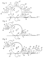
- the reference numeral 1 the output of a printing press, not shown, to which a painting station 2 is connected.
- a so-called display 3 printed sheets 4 printed on the upper side are conveyed to the painting station 2 in the printing machine, the delivery 3 for this purpose being an endlessly circulating conveyor belt 5 has, which transports the signatures 4 in the direction of the arrow 6.
- the painting station 2 comprises a housing 7 mounted on height-adjustable feet with a transfer roller 9 driven centrally about a horizontal axis 10 in the direction of the arrow 11.
- the peripheral surface 12 of the transfer roller 9 is preferably coated with highly polished ceramic surface.
- the circumferential surface 12 of the transfer roller 9 is preferably chromium-coated; however, if desired, it may also be ceramic coated or coated with another comparable material which allows the production of highly polished, closed surfaces as well as chrome or ceramic.
- UV ink is applied to the peripheral surface 12 in the exemplary embodiment, by means of a lacquer cylinder 13. This is supplied by a scoop roller 14 and metering roller 15 with UV varnish from a varnish reservoir 16 with UV varnish. In this construction is a well-known device-technical arrangement.
- the applied to the peripheral surface 12 of the transfer roller 9 paint is cured to form a UV paint film, by means of a paint cylinder 13 downstream UV emitter 17th
- Fig. 1 the UV emitter 17, an adhesive cylinder 18 downstream, which is supplied in a similar manner as the paint cylinder by an adhesive scoop roller 19 and adhesive metering roller 20 with adhesive from an adhesive bath 21.
- the adhesive cylinder is followed by an IR emitter 22 for precuring the adhesive layer applied to the paint film.
- the paint-adhesive composite film produced on the circumferential surface 12 of the transfer roller 9 is then in a gap between the transfer roller 9 and associated counter-roller 23 on the upper pressure side of Sheets 4 applied under intimate connection with the same.
- the paint is cured only by an IR or UV radiator 17, wherein the curing or drying on a set to about 100 ° C transfer surface or here circumferential surface 12 of the transfer roller 9 takes place.
- the radiator 17 is preferably arranged immediately in front of the gap between transfer roller 9 and associated counter-roller 23.
- the aforementioned transmission gap which defines a so-called transfer station 25, is followed by a device for final curing of the paint film and / or adhesive, in particular an ultrasonic generator.
- the final curing of paint and / or adhesive takes place only after transfer of the paint or lacquer-adhesive composite film on the printing side of the signatures 4.
- This procedure has the advantage that in the gap between transfer roller 9 and counter-roller 23 easily possible air pockets can be pressed out of the area between paint or adhesive composite film and printing side of the signatures 4.
- the not yet precured and thus still relatively soft paint and / or adhesive layer is no resistance to escaping air bubbles.
- a transfer station downstream device for final curing of the paint and / or adhesive layer is in Figs. 1, 3 and 5 with the Reference numeral 24 indicated.
- FIGS. 3 and 4 Schematically, the two illustrated painting stations are shown again in FIGS. 3 and 4. It can be clearly seen that at the station in Fig. 4, the adhesive transfer station 18-21 and the IR emitter 22 and the device 24 for curing the adhesive layer omitted.
- the station is therefore structurally less expensive, although a device for heating the chrome-coated peripheral surface 12 of the transfer roller 9 is required.
- FIG. 5 shows a third alternative embodiment of a painting station to those shown schematically in FIGS. 3 and 4.
- Glue is here applied by means of an adhesive transfer station 18-21 to the top of print media 4 prior to transfer of a paint film.
- the adhesive is applied immediately after application by means of an IR or. UV lamp 17 hardened.
- the transfer roller 9 which has a peripheral surface 12 made of chromium or ceramic, the paint film is transferred to the adhesive tops of the print media 4.
- the adhesive or paint-adhesive composite film is then cured.
Landscapes
- Toxicology (AREA)
- Physics & Mathematics (AREA)
- Health & Medical Sciences (AREA)
- General Health & Medical Sciences (AREA)
- Mechanical Engineering (AREA)
- Electromagnetism (AREA)
- Engineering & Computer Science (AREA)
- Thermal Sciences (AREA)
- Printing Methods (AREA)
- Application Of Or Painting With Fluid Materials (AREA)
- Supply, Installation And Extraction Of Printed Sheets Or Plates (AREA)
- Coating Apparatus (AREA)
- Decoration By Transfer Pictures (AREA)
Claims (20)
- Procédé d'application d'une couche de vernis sur la face supérieure d'un produit imprimé (feuille imprimée), caractérisé par les étapes suivantes :a) réalisation d'un film de vernis, en particulier un film de vernis sensible à l'ultraviolet ;b) séchage et durcissement du film de vernis sous l'effet de la chaleur et/ou des rayons ultraviolets ;c) transfert du film de vernis séché et durci sur la face supérieure fraîchement imprimée et/ou encore humide du produit imprimé par un collage simultané durable avec cette face supérieure.
- Procédé selon la revendication 1, caractérisé en ce que sur le film de vernis séché et durci est appliquée une colle, en particulier une colle sensible à l'ultraviolet moyennant la formation d'un film composite de vernis et colle, le film composite étant ensuite transféré avec le côté adhésif sur la face supérieure imprimée du produit imprimé.
- Procédé selon la revendication 2, caractérisé en ce que la colle est durcie soit directement après le transfert sur le film de vernis, soit après le transfert du film composite de vernis et colle sur la face supérieure imprimée du produit imprimé, en particulier sous l'effet de la chaleur, d'un rayonnement ultraviolet et/ou d'un rayonnement infrarouge et/ou des ultrasons.
- Procédé selon l'une quelconque des revendications 1 à 3, caractérisé en ce que pour la réalisation d'une surface vernie brillante, le vernis est appliqué sur une surface de transfert à poli spéculaire, en particulier la surface périphérique d'un cylindre de transfert, en particulier revêtue de céramique, le transfert sur la face supérieure du produit imprimé étant ensuite effectué de telle sorte que la face du film de vernis, en appui contre la surface à poli spéculaire, en particulier la surface céramique, définit la face supérieure ou face visible du produit imprimé vernis.
- Procédé selon l'une quelconque des revendications 1 à 4, caractérisé en ce que, à des fins de vernissage à façon, un film composite de vernis et colle est réalisé seulement par zones partielles et est transféré ou appliqué sur une zone partielle correspondante d'une face supérieure imprimée du produit imprimé.
- Procédé selon la revendication 1 ou 4, caractérisé en ce que le film de vernis est réglé à une température prédéterminée, en particulier environ 80°C à 110°C, par laquelle il durcit en lui-même, mais est auto-adhésif par rapport à des surfaces de plus faible température, de telle sorte qu'il peut être transféré directement sur la face supérieure fraîchement imprimée et/ou encore humide du produit imprimé.
- Procédé selon la revendication 1 ou 4, caractérisé en ce que le film de vernis séché et durci est transféré sur une face supérieure imprimée, revêtue au préalable de colle, du produit imprimé.
- Procédé selon la revendication 7, caractérisé en ce que la colle est durcie, en particulier sous l'effet de la chaleur et/ou des rayons ultraviolets, après l'application sur la face supérieure imprimée du produit imprimé.
- Dispositif destiné à la mise en oeuvre du procédé selon l'une quelconque des revendications 1 à 8, pour l'application d'une couche de vernis sur la face supérieure d'un produit imprimé, comportant un dispositif de transfert de vernis, destiné à la réalisation d'un film de vernis et auquel est associé un poste de transfert de vernis (13), un émetteur de chaleur ou de rayons UV (17) étant monté en aval de ce poste, et au moyen duquel le film de vernis réalisé sur celui-ci peut être transféré sur la face supérieure fraîchement imprimée du produit imprimé (4).
- Dispositif selon la revendication 9, caractérisé en ce que le dispositif de transfert de vernis (9) comporte une surface de transfert (12) à poli spéculaire, en particulier une surface en céramique, acier inoxydable ou chrome.
- Dispositif selon la revendication 10, caractérisé en ce que le dispositif de transfert de vernis est formé par un cylindre de transfert (9), dont la surface périphérique (12) est réalisée soit en acier inoxydable à poli spéculaire, en chrome ou dans des matériaux non ferreux, en particulier en céramique.
- Dispositif selon l'une quelconque des revendications 9 à 11, caractérisé en ce qu'au dispositif de transfert de vernis est associé un poste de transfert de colle (18), monté en aval du poste de transfert de vernis (13), en vue de réaliser un film composite de vernis et colle, l'émetteur de chaleur ou de rayons UV (17) étant monté entre les deux postes.
- Dispositif selon l'une quelconque des revendications 9 à 11, caractérisé en ce qu'un poste de transfert de colle (18), destiné à transférer un film de colle sur la face supérieure du produit imprimé (4), est monté en amont du dispositif de transfert de vernis.
- Dispositif selon la revendication 13, caractérisé en ce qu'un dispositif de durcissement de la colle, en particulier un émetteur de rayons IR ou UV (17), est monté entre le dispositif de transfert de vernis et le poste de transfert de colle (18).
- Dispositif selon l'une quelconque des revendications 12 à 14, caractérisé en ce qu'un dispositif de séchage de la colle (22 et/ou 24), monté en aval du poste de transfert de colle (18), est associé au dispositif de transfert de vernis (9).
- Dispositif selon la revendication 15, caractérisé en ce que le dispositif de séchage de la colle (24) est monté en aval du poste de transfert (25), dans lequel le film composite de vernis et colle est appliqué avec sa face adhésive ou le film de vernis sur la face supérieure imprimée du produit imprimé (4).
- Dispositif selon la revendication 15 ou 16, caractérisé en ce que le dispositif de séchage de la colle est un émetteur de rayons IR (22), un émetteur de rayons UV ou un générateur d'ultrasons (24).
- Dispositif selon l'une quelconque des revendications 9 à 17, caractérisé en ce que le transfert du film de vernis ou du film composite de vernis et colle est effectué dans une fente (25) entre la surface de transfert (12) et un contre-cylindre (23).
- Dispositif selon l'une quelconque des revendications 9 à 11, caractérisé en ce que le dispositif de transfert de vernis est réglé à une température de surface prédéterminée, en particulier environ 80°C à 110°C.
- Dispositif selon l'une quelconque des revendications 9 à 19, caractérisé en ce que pour le vernissage à façon au moyen d'un cylindre de forte pression à vernis et, le cas échéant, à colle, le vernis et, le cas échéant, la colle peuvent être appliqués, en particulier de manière coïncidente, seulement par zones partielles sur la surface de transfert (12) du dispositif de transfert (9).
Applications Claiming Priority (3)
| Application Number | Priority Date | Filing Date | Title |
|---|---|---|---|
| DE10022939A DE10022939A1 (de) | 2000-05-11 | 2000-05-11 | Verfahren und Vorrichtung zum Auftragen einer Lackschicht auf die Oberseite eines Druckmediums |
| DE10022939 | 2000-05-11 | ||
| PCT/EP2001/005273 WO2001085456A1 (fr) | 2000-05-11 | 2001-05-09 | Procede et dispositif pour appliquer une couche de vernis sur la face superieure d'un support d'impression |
Publications (2)
| Publication Number | Publication Date |
|---|---|
| EP1282517A1 EP1282517A1 (fr) | 2003-02-12 |
| EP1282517B1 true EP1282517B1 (fr) | 2006-08-09 |
Family
ID=7641557
Family Applications (1)
| Application Number | Title | Priority Date | Filing Date |
|---|---|---|---|
| EP01949328A Expired - Lifetime EP1282517B1 (fr) | 2000-05-11 | 2001-05-09 | Procede et dispositif pour appliquer une couche de vernis sur la face superieure d'un support d'impression |
Country Status (6)
| Country | Link |
|---|---|
| US (1) | US6808584B2 (fr) |
| EP (1) | EP1282517B1 (fr) |
| JP (1) | JP2003532530A (fr) |
| AT (1) | ATE335608T1 (fr) |
| DE (2) | DE10022939A1 (fr) |
| WO (1) | WO2001085456A1 (fr) |
Families Citing this family (11)
| Publication number | Priority date | Publication date | Assignee | Title |
|---|---|---|---|---|
| JP2005119276A (ja) * | 2003-09-26 | 2005-05-12 | Canon Inc | 画像記録方法並びに装置 |
| DE102004060059A1 (de) * | 2004-12-14 | 2006-06-29 | Man Roland Druckmaschinen Ag | Rotationsdruckmaschine mit integrierter Lackiereinrichtung |
| DE102004061952A1 (de) | 2004-12-23 | 2006-07-06 | Man Roland Druckmaschinen Ag | Verfahren zum Kaschieren |
| DE102006015474A1 (de) * | 2006-03-31 | 2007-10-04 | Heidelberger Druckmaschinen Ag | Folientransferwerk mit integrierter Weiterverarbeitungseinrichtung |
| DE102006051275A1 (de) * | 2006-10-31 | 2008-05-08 | Man Roland Druckmaschinen Ag | Veredelungsverfahren für ein Druckprodukt und Beschichtungseinheit |
| DE102007031051A1 (de) * | 2007-07-04 | 2009-01-08 | Manroland Ag | Kaschiertes Druckprodukt und Verfahren zur Herstellung desselben |
| DE102009038032A1 (de) | 2008-09-03 | 2010-03-04 | Heidelberger Druckmaschinen Ag | Verfahren zum Lackieren von Bogen |
| DE102012004634A1 (de) | 2011-03-28 | 2012-10-04 | Heidelberger Druckmaschinen Ag | Verfahren zum Erzeugen einer Schicht auf einem Substrat |
| ES2398833B1 (es) * | 2011-08-18 | 2014-01-29 | Comexi Group Industries, Sau | Aparato y método para la fabricación de un producto impreso laminado |
| DE102012021819A1 (de) | 2012-11-07 | 2014-05-08 | Heidelberger Druckmaschinen Ag | Verfahren zum Beschichten von Bogen mit einem Film in einer Druckmaschine |
| US11383545B2 (en) * | 2019-05-01 | 2022-07-12 | Xerox Corporation | Apparatus and method for deposting an overcoat on an image on a substrate |
Family Cites Families (9)
| Publication number | Priority date | Publication date | Assignee | Title |
|---|---|---|---|---|
| JPS6056101B2 (ja) * | 1980-09-25 | 1985-12-09 | 東レ株式会社 | ポリエステルフイルムの製造方法 |
| DE3513291A1 (de) * | 1985-04-13 | 1986-10-16 | Heidelberger Druckmaschinen Ag, 6900 Heidelberg | Vorrichtung zum lackieren an rotationsdruckmaschinen |
| US4840757A (en) * | 1987-05-19 | 1989-06-20 | S. D. Warren Company | Replicating process for interference patterns |
| US5368891A (en) | 1988-05-26 | 1994-11-29 | Sakata Inkusu Kabushikikaisha | Method and apparatus for producing glossy printed matter |
| JP2651459B2 (ja) * | 1988-05-26 | 1997-09-10 | サカタインクス 株式会社 | 光沢印刷物の製造方法及びそれに適した装置 |
| DE4215070A1 (de) * | 1992-05-07 | 1993-11-11 | Herberts Gmbh | Verfahren zur Herstellung von Mehrschichtlackierungen |
| US5406641A (en) * | 1993-06-15 | 1995-04-11 | Rohm And Haas Company | Flexible light pipe, cured composite and processes for preparation thereof |
| KR100271920B1 (ko) * | 1998-01-30 | 2000-11-15 | 김양평 | 라미네이트방법 |
| GB2338434B (en) * | 1998-03-23 | 2001-08-22 | Whiley Foils Ltd | Hot dieless foiling |
-
2000
- 2000-05-11 DE DE10022939A patent/DE10022939A1/de not_active Withdrawn
-
2001
- 2001-05-09 WO PCT/EP2001/005273 patent/WO2001085456A1/fr active IP Right Grant
- 2001-05-09 DE DE50110704T patent/DE50110704D1/de not_active Expired - Fee Related
- 2001-05-09 EP EP01949328A patent/EP1282517B1/fr not_active Expired - Lifetime
- 2001-05-09 JP JP2001582090A patent/JP2003532530A/ja active Pending
- 2001-05-09 AT AT01949328T patent/ATE335608T1/de not_active IP Right Cessation
-
2002
- 2002-11-12 US US10/292,845 patent/US6808584B2/en not_active Expired - Fee Related
Also Published As
| Publication number | Publication date |
|---|---|
| US6808584B2 (en) | 2004-10-26 |
| US20030116263A1 (en) | 2003-06-26 |
| EP1282517A1 (fr) | 2003-02-12 |
| DE50110704D1 (de) | 2006-09-21 |
| JP2003532530A (ja) | 2003-11-05 |
| DE10022939A1 (de) | 2001-11-15 |
| WO2001085456A9 (fr) | 2002-08-08 |
| WO2001085456A1 (fr) | 2001-11-15 |
| ATE335608T1 (de) | 2006-09-15 |
Similar Documents
| Publication | Publication Date | Title |
|---|---|---|
| EP0578706B1 (fr) | Procede et machine d'impression par decalquage | |
| DE10362054B4 (de) | Offsetdruckverfahren und Druckerzeugnis | |
| EP2148746B1 (fr) | Procédé et dispositif de revêtement d'une pièce plate avec une substance fluide | |
| DE69711538T2 (de) | Verfahren zur Herstellung einer Dekorfolie und Vorrichtung zu seiner Herstellung | |
| EP2155490B1 (fr) | Procédé et dispositif de revêtement décoratif d'un panneau | |
| EP2050514B1 (fr) | Procédé et dispositif de fabrication d'une surface structurée d'une plaque de matière laquée | |
| DE2557551A1 (de) | Verfahren und vorrichtung zur aufbringung von fluiden | |
| EP1282517B1 (fr) | Procede et dispositif pour appliquer une couche de vernis sur la face superieure d'un support d'impression | |
| DE102015218333A1 (de) | Wellpappeanlage | |
| DE2649479B2 (de) | HeiBprägefolie sowie Verfahren und Vorrichtung zu ihrer Herstellung | |
| DE112005001559T5 (de) | Verfahren und Vorrichtung zum Streichen eines Substrates und Drucksache | |
| EP3208088B1 (fr) | Dispositif d'estampage à chaud | |
| EP2082898B1 (fr) | Roleau imprimeur et procédé destinés à l'application d'un décor sur un élément de plaque | |
| EP4028261B1 (fr) | Procédé et dispositif de finition d'épreuves | |
| DE3501765A1 (de) | Verfahren und vorrichtung zur versiegelung von informationen auf kartenfoermigen informationstraegern | |
| EP3539792A1 (fr) | Procédé de fabrication de structures sur un substrat | |
| DE3221974C2 (de) | Verfahren zum Glätten bedruckter Flächen bei dickem Farbauftrag und Vorrichtung zur Durchführung desselben | |
| EP0930161B1 (fr) | Méthode et dispositf pour le revêtement de produits imprimés | |
| DE10360187C5 (de) | Verfahren und Vorrichtung zur Herstellung einer beschichteten Platte | |
| DE69808296T2 (de) | Verfahren zum betreiben einer druckeinheit und druckeinheit für eine offsetmaschine | |
| WO2008116483A1 (fr) | Dispositif et procédé d'appliquer sur un objet un élément décoratif adhérant sur un film | |
| EP1129952B1 (fr) | Méthode et dispositif pour l'application de decalcomanies sur conteneurs | |
| DE2628306A1 (de) | Verfahren zum aufbringen sichtbaren materials auf mindestens eine seitenflaeche eines blockes und block | |
| WO2008116484A1 (fr) | Dispositif et procédé pour appliquer sur un objet multidimensionnel un élément décoratif adhérant sur un film | |
| DE102023109411A1 (de) | Verfahren und Vorrichtung zum Herstellen eines mehrschichtigen Bodenbelags |
Legal Events
| Date | Code | Title | Description |
|---|---|---|---|
| PUAI | Public reference made under article 153(3) epc to a published international application that has entered the european phase |
Free format text: ORIGINAL CODE: 0009012 |
|
| 17P | Request for examination filed |
Effective date: 20021211 |
|
| AK | Designated contracting states |
Designated state(s): AT BE CH CY DE DK ES FI FR GB GR IE IT LI LU MC NL PT SE TR |
|
| GRAP | Despatch of communication of intention to grant a patent |
Free format text: ORIGINAL CODE: EPIDOSNIGR1 |
|
| GRAS | Grant fee paid |
Free format text: ORIGINAL CODE: EPIDOSNIGR3 |
|
| GRAA | (expected) grant |
Free format text: ORIGINAL CODE: 0009210 |
|
| AK | Designated contracting states |
Kind code of ref document: B1 Designated state(s): AT BE CH CY DE DK ES FI FR GB GR IE IT LI LU MC NL PT SE TR |
|
| PG25 | Lapsed in a contracting state [announced via postgrant information from national office to epo] |
Ref country code: NL Free format text: LAPSE BECAUSE OF FAILURE TO SUBMIT A TRANSLATION OF THE DESCRIPTION OR TO PAY THE FEE WITHIN THE PRESCRIBED TIME-LIMIT Effective date: 20060809 Ref country code: IT Free format text: LAPSE BECAUSE OF FAILURE TO SUBMIT A TRANSLATION OF THE DESCRIPTION OR TO PAY THE FEE WITHIN THE PRESCRIBED TIME-LIMIT;WARNING: LAPSES OF ITALIAN PATENTS WITH EFFECTIVE DATE BEFORE 2007 MAY HAVE OCCURRED AT ANY TIME BEFORE 2007. THE CORRECT EFFECTIVE DATE MAY BE DIFFERENT FROM THE ONE RECORDED. Effective date: 20060809 Ref country code: GB Free format text: LAPSE BECAUSE OF FAILURE TO SUBMIT A TRANSLATION OF THE DESCRIPTION OR TO PAY THE FEE WITHIN THE PRESCRIBED TIME-LIMIT Effective date: 20060809 Ref country code: FI Free format text: LAPSE BECAUSE OF FAILURE TO SUBMIT A TRANSLATION OF THE DESCRIPTION OR TO PAY THE FEE WITHIN THE PRESCRIBED TIME-LIMIT Effective date: 20060809 Ref country code: IE Free format text: LAPSE BECAUSE OF FAILURE TO SUBMIT A TRANSLATION OF THE DESCRIPTION OR TO PAY THE FEE WITHIN THE PRESCRIBED TIME-LIMIT Effective date: 20060809 |
|
| REG | Reference to a national code |
Ref country code: GB Ref legal event code: FG4D Free format text: NOT ENGLISH |
|
| REG | Reference to a national code |
Ref country code: CH Ref legal event code: EP |
|
| REG | Reference to a national code |
Ref country code: IE Ref legal event code: FG4D Free format text: LANGUAGE OF EP DOCUMENT: GERMAN |
|
| REG | Reference to a national code |
Ref country code: CH Ref legal event code: NV Representative=s name: TROESCH SCHEIDEGGER WERNER AG |
|
| REF | Corresponds to: |
Ref document number: 50110704 Country of ref document: DE Date of ref document: 20060921 Kind code of ref document: P |
|
| PG25 | Lapsed in a contracting state [announced via postgrant information from national office to epo] |
Ref country code: DK Free format text: LAPSE BECAUSE OF FAILURE TO SUBMIT A TRANSLATION OF THE DESCRIPTION OR TO PAY THE FEE WITHIN THE PRESCRIBED TIME-LIMIT Effective date: 20061109 Ref country code: SE Free format text: LAPSE BECAUSE OF FAILURE TO SUBMIT A TRANSLATION OF THE DESCRIPTION OR TO PAY THE FEE WITHIN THE PRESCRIBED TIME-LIMIT Effective date: 20061109 |
|
| PG25 | Lapsed in a contracting state [announced via postgrant information from national office to epo] |
Ref country code: ES Free format text: LAPSE BECAUSE OF FAILURE TO SUBMIT A TRANSLATION OF THE DESCRIPTION OR TO PAY THE FEE WITHIN THE PRESCRIBED TIME-LIMIT Effective date: 20061120 |
|
| PG25 | Lapsed in a contracting state [announced via postgrant information from national office to epo] |
Ref country code: PT Free format text: LAPSE BECAUSE OF FAILURE TO SUBMIT A TRANSLATION OF THE DESCRIPTION OR TO PAY THE FEE WITHIN THE PRESCRIBED TIME-LIMIT Effective date: 20070109 |
|
| NLV1 | Nl: lapsed or annulled due to failure to fulfill the requirements of art. 29p and 29m of the patents act | ||
| GBV | Gb: ep patent (uk) treated as always having been void in accordance with gb section 77(7)/1977 [no translation filed] |
Effective date: 20060809 |
|
| REG | Reference to a national code |
Ref country code: IE Ref legal event code: FD4D |
|
| EN | Fr: translation not filed | ||
| PGFP | Annual fee paid to national office [announced via postgrant information from national office to epo] |
Ref country code: AT Payment date: 20070521 Year of fee payment: 7 |
|
| PGFP | Annual fee paid to national office [announced via postgrant information from national office to epo] |
Ref country code: CH Payment date: 20070522 Year of fee payment: 7 |
|
| PGFP | Annual fee paid to national office [announced via postgrant information from national office to epo] |
Ref country code: DE Payment date: 20070531 Year of fee payment: 7 |
|
| PLBE | No opposition filed within time limit |
Free format text: ORIGINAL CODE: 0009261 |
|
| STAA | Information on the status of an ep patent application or granted ep patent |
Free format text: STATUS: NO OPPOSITION FILED WITHIN TIME LIMIT |
|
| 26N | No opposition filed |
Effective date: 20070510 |
|
| BERE | Be: lapsed |
Owner name: KASBAUER, HANS Effective date: 20070531 |
|
| PG25 | Lapsed in a contracting state [announced via postgrant information from national office to epo] |
Ref country code: MC Free format text: LAPSE BECAUSE OF NON-PAYMENT OF DUE FEES Effective date: 20070531 |
|
| PG25 | Lapsed in a contracting state [announced via postgrant information from national office to epo] |
Ref country code: BE Free format text: LAPSE BECAUSE OF NON-PAYMENT OF DUE FEES Effective date: 20070531 |
|
| PG25 | Lapsed in a contracting state [announced via postgrant information from national office to epo] |
Ref country code: FR Free format text: LAPSE BECAUSE OF FAILURE TO SUBMIT A TRANSLATION OF THE DESCRIPTION OR TO PAY THE FEE WITHIN THE PRESCRIBED TIME-LIMIT Effective date: 20070511 Ref country code: GR Free format text: LAPSE BECAUSE OF FAILURE TO SUBMIT A TRANSLATION OF THE DESCRIPTION OR TO PAY THE FEE WITHIN THE PRESCRIBED TIME-LIMIT Effective date: 20061110 |
|
| PG25 | Lapsed in a contracting state [announced via postgrant information from national office to epo] |
Ref country code: FR Free format text: LAPSE BECAUSE OF FAILURE TO SUBMIT A TRANSLATION OF THE DESCRIPTION OR TO PAY THE FEE WITHIN THE PRESCRIBED TIME-LIMIT Effective date: 20060809 |
|
| REG | Reference to a national code |
Ref country code: CH Ref legal event code: PL |
|
| PG25 | Lapsed in a contracting state [announced via postgrant information from national office to epo] |
Ref country code: CH Free format text: LAPSE BECAUSE OF NON-PAYMENT OF DUE FEES Effective date: 20080531 Ref country code: LI Free format text: LAPSE BECAUSE OF NON-PAYMENT OF DUE FEES Effective date: 20080531 |
|
| PG25 | Lapsed in a contracting state [announced via postgrant information from national office to epo] |
Ref country code: AT Free format text: LAPSE BECAUSE OF NON-PAYMENT OF DUE FEES Effective date: 20080509 |
|
| PG25 | Lapsed in a contracting state [announced via postgrant information from national office to epo] |
Ref country code: DE Free format text: LAPSE BECAUSE OF NON-PAYMENT OF DUE FEES Effective date: 20081202 |
|
| PG25 | Lapsed in a contracting state [announced via postgrant information from national office to epo] |
Ref country code: LU Free format text: LAPSE BECAUSE OF NON-PAYMENT OF DUE FEES Effective date: 20070509 Ref country code: CY Free format text: LAPSE BECAUSE OF FAILURE TO SUBMIT A TRANSLATION OF THE DESCRIPTION OR TO PAY THE FEE WITHIN THE PRESCRIBED TIME-LIMIT Effective date: 20060809 |
|
| PG25 | Lapsed in a contracting state [announced via postgrant information from national office to epo] |
Ref country code: TR Free format text: LAPSE BECAUSE OF FAILURE TO SUBMIT A TRANSLATION OF THE DESCRIPTION OR TO PAY THE FEE WITHIN THE PRESCRIBED TIME-LIMIT Effective date: 20060809 |