EP1282115B1 - Kopfeinstellvorrichtung und Informationsaufzeichnungs/-wiedergabegerät - Google Patents
Kopfeinstellvorrichtung und Informationsaufzeichnungs/-wiedergabegerät Download PDFInfo
- Publication number
- EP1282115B1 EP1282115B1 EP02016880.3A EP02016880A EP1282115B1 EP 1282115 B1 EP1282115 B1 EP 1282115B1 EP 02016880 A EP02016880 A EP 02016880A EP 1282115 B1 EP1282115 B1 EP 1282115B1
- Authority
- EP
- European Patent Office
- Prior art keywords
- head
- fine
- actuator
- coarse
- unit
- Prior art date
- Legal status (The legal status is an assumption and is not a legal conclusion. Google has not performed a legal analysis and makes no representation as to the accuracy of the status listed.)
- Expired - Lifetime
Links
- 238000000034 method Methods 0.000 claims description 48
- 230000000670 limiting effect Effects 0.000 claims description 45
- 238000003487 electrochemical reaction Methods 0.000 claims description 43
- 230000006866 deterioration Effects 0.000 claims description 31
- 230000001276 controlling effect Effects 0.000 claims description 26
- 238000000354 decomposition reaction Methods 0.000 claims description 26
- 230000007246 mechanism Effects 0.000 claims description 24
- XLYOFNOQVPJJNP-UHFFFAOYSA-N water Substances O XLYOFNOQVPJJNP-UHFFFAOYSA-N 0.000 claims description 21
- 230000000694 effects Effects 0.000 claims description 15
- 230000001105 regulatory effect Effects 0.000 claims description 15
- 238000003860 storage Methods 0.000 claims description 15
- 239000010408 film Substances 0.000 claims description 12
- 238000007689 inspection Methods 0.000 claims description 9
- 230000015556 catabolic process Effects 0.000 claims description 8
- 238000001514 detection method Methods 0.000 claims description 8
- 239000010409 thin film Substances 0.000 claims description 5
- MCMNRKCIXSYSNV-UHFFFAOYSA-N Zirconium dioxide Chemical compound O=[Zr]=O MCMNRKCIXSYSNV-UHFFFAOYSA-N 0.000 claims description 4
- 239000010936 titanium Substances 0.000 claims description 4
- RTAQQCXQSZGOHL-UHFFFAOYSA-N Titanium Chemical compound [Ti] RTAQQCXQSZGOHL-UHFFFAOYSA-N 0.000 claims description 3
- 229910052719 titanium Inorganic materials 0.000 claims description 2
- 238000006073 displacement reaction Methods 0.000 description 85
- 238000010586 diagram Methods 0.000 description 24
- 238000001556 precipitation Methods 0.000 description 23
- HTUMBQDCCIXGCV-UHFFFAOYSA-N lead oxide Chemical compound [O-2].[Pb+2] HTUMBQDCCIXGCV-UHFFFAOYSA-N 0.000 description 16
- 238000005868 electrolysis reaction Methods 0.000 description 14
- 238000004088 simulation Methods 0.000 description 14
- 238000006243 chemical reaction Methods 0.000 description 13
- 230000003628 erosive effect Effects 0.000 description 12
- 230000002829 reductive effect Effects 0.000 description 12
- QVGXLLKOCUKJST-UHFFFAOYSA-N atomic oxygen Chemical compound [O] QVGXLLKOCUKJST-UHFFFAOYSA-N 0.000 description 11
- 239000001301 oxygen Substances 0.000 description 11
- 229910052760 oxygen Inorganic materials 0.000 description 11
- 150000002500 ions Chemical class 0.000 description 10
- 238000012545 processing Methods 0.000 description 10
- 230000001965 increasing effect Effects 0.000 description 8
- -1 hydroxyl ions Chemical class 0.000 description 6
- 229910000464 lead oxide Inorganic materials 0.000 description 6
- 238000004519 manufacturing process Methods 0.000 description 6
- 239000012466 permeate Substances 0.000 description 6
- 230000001360 synchronised effect Effects 0.000 description 6
- 238000004364 calculation method Methods 0.000 description 5
- 230000010355 oscillation Effects 0.000 description 5
- 239000002244 precipitate Substances 0.000 description 5
- 230000035945 sensitivity Effects 0.000 description 5
- 230000004886 head movement Effects 0.000 description 4
- 239000000203 mixture Substances 0.000 description 4
- 239000013078 crystal Substances 0.000 description 3
- XLYOFNOQVPJJNP-ZSJDYOACSA-N heavy water Substances [2H]O[2H] XLYOFNOQVPJJNP-ZSJDYOACSA-N 0.000 description 3
- 239000000463 material Substances 0.000 description 3
- 238000005070 sampling Methods 0.000 description 3
- 230000004913 activation Effects 0.000 description 2
- 230000002411 adverse Effects 0.000 description 2
- 238000013459 approach Methods 0.000 description 2
- 238000005229 chemical vapour deposition Methods 0.000 description 2
- 150000001875 compounds Chemical class 0.000 description 2
- 230000001143 conditioned effect Effects 0.000 description 2
- 230000007423 decrease Effects 0.000 description 2
- 238000009826 distribution Methods 0.000 description 2
- 230000001747 exhibiting effect Effects 0.000 description 2
- 230000009191 jumping Effects 0.000 description 2
- 230000007774 longterm Effects 0.000 description 2
- 239000002184 metal Substances 0.000 description 2
- 229910052751 metal Inorganic materials 0.000 description 2
- 230000002265 prevention Effects 0.000 description 2
- 230000004044 response Effects 0.000 description 2
- 238000005245 sintering Methods 0.000 description 2
- 239000000126 substance Substances 0.000 description 2
- 239000000725 suspension Substances 0.000 description 2
- UFHFLCQGNIYNRP-UHFFFAOYSA-N Hydrogen Chemical compound [H][H] UFHFLCQGNIYNRP-UHFFFAOYSA-N 0.000 description 1
- 229910020294 Pb(Zr,Ti)O3 Inorganic materials 0.000 description 1
- 229910001069 Ti alloy Inorganic materials 0.000 description 1
- 239000002253 acid Substances 0.000 description 1
- 230000002378 acidificating effect Effects 0.000 description 1
- 239000000919 ceramic Substances 0.000 description 1
- 238000007796 conventional method Methods 0.000 description 1
- 230000003247 decreasing effect Effects 0.000 description 1
- 230000005484 gravity Effects 0.000 description 1
- 238000000227 grinding Methods 0.000 description 1
- 239000001257 hydrogen Substances 0.000 description 1
- 229910052739 hydrogen Inorganic materials 0.000 description 1
- GPRLSGONYQIRFK-UHFFFAOYSA-N hydron Chemical compound [H+] GPRLSGONYQIRFK-UHFFFAOYSA-N 0.000 description 1
- 239000012535 impurity Substances 0.000 description 1
- 230000001939 inductive effect Effects 0.000 description 1
- 230000002401 inhibitory effect Effects 0.000 description 1
- 238000013178 mathematical model Methods 0.000 description 1
- 230000003287 optical effect Effects 0.000 description 1
- 231100000572 poisoning Toxicity 0.000 description 1
- 230000000607 poisoning effect Effects 0.000 description 1
- 230000001376 precipitating effect Effects 0.000 description 1
- 230000002035 prolonged effect Effects 0.000 description 1
- 230000036632 reaction speed Effects 0.000 description 1
- 239000004065 semiconductor Substances 0.000 description 1
- 238000004544 sputter deposition Methods 0.000 description 1
- 230000002195 synergetic effect Effects 0.000 description 1
- 238000012360 testing method Methods 0.000 description 1
Images










Classifications
-
- G—PHYSICS
- G11—INFORMATION STORAGE
- G11B—INFORMATION STORAGE BASED ON RELATIVE MOVEMENT BETWEEN RECORD CARRIER AND TRANSDUCER
- G11B21/00—Head arrangements not specific to the method of recording or reproducing
- G11B21/02—Driving or moving of heads
- G11B21/08—Track changing or selecting during transducing operation
- G11B21/081—Access to indexed tracks or parts of continuous track
- G11B21/083—Access to indexed tracks or parts of continuous track on discs
- G11B21/085—Access to indexed tracks or parts of continuous track on discs with track following of accessed part
-
- G—PHYSICS
- G11—INFORMATION STORAGE
- G11B—INFORMATION STORAGE BASED ON RELATIVE MOVEMENT BETWEEN RECORD CARRIER AND TRANSDUCER
- G11B21/00—Head arrangements not specific to the method of recording or reproducing
- G11B21/02—Driving or moving of heads
- G11B21/10—Track finding or aligning by moving the head ; Provisions for maintaining alignment of the head relative to the track during transducing operation, i.e. track following
- G11B21/106—Track finding or aligning by moving the head ; Provisions for maintaining alignment of the head relative to the track during transducing operation, i.e. track following on disks
-
- G—PHYSICS
- G11—INFORMATION STORAGE
- G11B—INFORMATION STORAGE BASED ON RELATIVE MOVEMENT BETWEEN RECORD CARRIER AND TRANSDUCER
- G11B21/00—Head arrangements not specific to the method of recording or reproducing
- G11B21/16—Supporting the heads; Supporting the sockets for plug-in heads
- G11B21/18—Supporting the heads; Supporting the sockets for plug-in heads while the head is moving
-
- G—PHYSICS
- G11—INFORMATION STORAGE
- G11B—INFORMATION STORAGE BASED ON RELATIVE MOVEMENT BETWEEN RECORD CARRIER AND TRANSDUCER
- G11B5/00—Recording by magnetisation or demagnetisation of a record carrier; Reproducing by magnetic means; Record carriers therefor
- G11B5/48—Disposition or mounting of heads or head supports relative to record carriers ; arrangements of heads, e.g. for scanning the record carrier to increase the relative speed
- G11B5/4806—Disposition or mounting of heads or head supports relative to record carriers ; arrangements of heads, e.g. for scanning the record carrier to increase the relative speed specially adapted for disk drive assemblies, e.g. assembly prior to operation, hard or flexible disk drives
- G11B5/4826—Mounting, aligning or attachment of the transducer head relative to the arm assembly, e.g. slider holding members, gimbals, adhesive
-
- G—PHYSICS
- G11—INFORMATION STORAGE
- G11B—INFORMATION STORAGE BASED ON RELATIVE MOVEMENT BETWEEN RECORD CARRIER AND TRANSDUCER
- G11B5/00—Recording by magnetisation or demagnetisation of a record carrier; Reproducing by magnetic means; Record carriers therefor
- G11B5/48—Disposition or mounting of heads or head supports relative to record carriers ; arrangements of heads, e.g. for scanning the record carrier to increase the relative speed
- G11B5/54—Disposition or mounting of heads or head supports relative to record carriers ; arrangements of heads, e.g. for scanning the record carrier to increase the relative speed with provision for moving the head into or out of its operative position or across tracks
- G11B5/55—Track change, selection or acquisition by displacement of the head
- G11B5/5521—Track change, selection or acquisition by displacement of the head across disk tracks
- G11B5/5552—Track change, selection or acquisition by displacement of the head across disk tracks using fine positioning means for track acquisition separate from the coarse (e.g. track changing) positioning means
-
- G—PHYSICS
- G11—INFORMATION STORAGE
- G11B—INFORMATION STORAGE BASED ON RELATIVE MOVEMENT BETWEEN RECORD CARRIER AND TRANSDUCER
- G11B5/00—Recording by magnetisation or demagnetisation of a record carrier; Reproducing by magnetic means; Record carriers therefor
- G11B5/48—Disposition or mounting of heads or head supports relative to record carriers ; arrangements of heads, e.g. for scanning the record carrier to increase the relative speed
- G11B5/58—Disposition or mounting of heads or head supports relative to record carriers ; arrangements of heads, e.g. for scanning the record carrier to increase the relative speed with provision for moving the head for the purpose of maintaining alignment of the head relative to the record carrier during transducing operation, e.g. to compensate for surface irregularities of the latter or for track following
- G11B5/596—Disposition or mounting of heads or head supports relative to record carriers ; arrangements of heads, e.g. for scanning the record carrier to increase the relative speed with provision for moving the head for the purpose of maintaining alignment of the head relative to the record carrier during transducing operation, e.g. to compensate for surface irregularities of the latter or for track following for track following on disks
Definitions
- This invention relates to a head positioning method and to a head positioner employing a dual-stage actuator method.
- a record/replay head (“record” and “replay” hereinbelow will also be referred to as “write” and “read”, respectively) is position-controlled through cooperative operations of a coarse actuator and a fine actuator.
- This invention relates to a a head positioning method and to a head positioner having a configuration employing the dual-stage actuator method, wherein a fine actuator is configured using a piezoelectric device.
- the head positioner of the invention is primarily mounted on a magnetic disk drive, the invention is not limited thereby.
- the head positioner of the invention may be mounted another information storage apparatus, such as a magnetooptical disk drive, or an optical disk drive.
- the invention also relates to an information recording/replaying apparatus represented by a magnetic disk drive.
- apparatuses for performing high-speed and high-accuracy positioning of a write/read head over an information storage disk such as a hard disk include a dual-stage-type head positioner formed of a coarse actuator and a fine actuator(s).
- the fine actuator is generally called a "microacuator (MA)", “dual-stage actuator”, or “piggyback actuator”.
- a piezoelectric device (PZT device) is widely used to form the fine actuator.
- VCM voice coil motor
- the coarse actuator is used for large movement as in a seeking operation or a multitrack jumping operation.
- the coarse actuator drive a head-mounted supporting mechanism to rotationally move on an axis on a chassis.
- the fine actuator used to perform high-speed and fine positioning as in a track following operation and a single-track jumping operation.
- the fine actuator is configured with the piezoelectric device being disposed between the coarse actuator and a head slider.
- the amount of head displacement is adjusted by controlling application voltage for the piezoelectric device constituting the fine actuator.
- the displacement stress increases proportionally to the increase in the level of the application voltage. This enables head positioning with improved sensitivity.
- a metal component in the piezoelectric device causes an electrochemical reaction, thereby precipitating the metal component in the electrodes.
- a thin-film PZT device made of a lead-zirconia-titanium alloy.
- the PZT device is not formed only of PZT crystal, and the device is doped with, for example, lead oxide and water in the fabrication.
- lead, water, and the like are included, the electrochemical reaction is activated in a voltage-applied state, phenomena occur in which lead is precipitated on the cathodic side.
- the lead precipitation phenomena In proportion to the increase in the application voltage, the lead precipitation phenomena increasingly tend to occur. Although adverse effects of the lead precipitation do not immediately occur prominent, the lead precipitation gradually advances. When erosion phenomena due to long-term lead precipitation continue, the displacement property of the piezoelectric device deteriorates. Further continuation of the erosion phenomena can disable the piezoelectric device to be displaced. Finally, the lead precipitation causes shortcircuiting, thereby causing breakdown of the piezoelectric device.
- the aforementioned configuration includes a plurality of heads for independently accessing a plurality of disks, a plurality of fine actuators for finely displacing the individual heads, a plurality of head supporting mechanisms for individually supporting the fine actuators, and a coarse actuator for batch-driving the plurality of head supporting mechanisms.
- Generally known conventional methods for driving the coarse actuator include a method as described in the following paragraphs.
- Weightings are individually added to relative displacement signals of a plurality of fine actuators, and a coarse actuator is controlled to converge each of the weighting-added signals to zero.
- the relative displacement signals are weighted according to importances preliminarily allocated to individual heads. The importance typically determines the priority in the access order.
- the coarse actuator is controlled on the basis of the importances set to weighting points, and weightings are added to all the relative displacement signals, problems are arisen in that the head supporting mechanism is frequently moved, and oscillations are caused thereby.
- the highest-importance head When a large wobbly movement occurs with a desired track corresponding to a head having the highest importance, the highest-importance head is maximally displaced. Accordingly, the value of the corresponding relative displacement signal becomes largest, and the amount of operation of the coarse actuator is large in proportion to the greatest weighting added to the relative displacement signal of the highest-importance head. Thereby, the individual fine actuators are over-displaced. Since the frequency of access-command issuance to the highest-importance head is high, the individual fine actuators are induced to cause oscillations. The oscillations influence the structural stability of each of the fine actuators. In addition, structural resonances are caused due to inter-fine actuator mutual interference. A condition occurs such that the positioning control itself of the head toward a desired track introduces a positional deviation from the desired track. Consequently, for example, read or write errors tend to occur at the desired track.
- US 6,188,548 B1 is concerned with a low voltage, high displacement microactuated disk drive suspension and discloses a head positioner, having a load beam for supporting a write/read head for accessing a disk.
- the load beam can be mounted to a coarse actuator by means of a mounting plate having a boss.
- Piezoelectric crystals are provided as a fine actuator for providing fine positioning control of the head relative to the tracks on a disk by pivoting a front beam portion of the load beam relative to its base portion.
- the driving signal supplied to the piezoelectric elements is limited to be less than 40 volts.
- US 6,052,251 discloses an actuator arm integrated piezoelectric microactuator which is controlled by a piezoelectric element controller to perform fine positioning of a read/write head relative to the tracks on a disk.
- a threshold or maximum value of the voltage supplied to the piezoelement is not explicitly mentioned.
- US 6,088,187 is concerned with a control system for a two-stage actuator for positioning a read/write head relative to the tracks of a rotatable information storage disk.
- the control system for controlling a coarse actuator and a fine actuator includes a feedback device for calculating a position error between a target position and an observed position of the head. The position error is input into the coarse actuator controller and the fine actuator controller. The displacement of the fine actuator relative to the coarse actuator is not input into the coarse actuator controller.
- US 6,100,623 is concerned with a piezoelectric actuator for control and displacement sensing and discloses another head positioner employing a dual-stage actuator method. Limitation of the control voltage for the piezoelectric actuator is not mentioned in this document.
- WO 99/66501 relates to a disk drive having charge feedback driven microactuator that includes a piezoelectric element.
- the voltage supplied to the piezoelectric elements of the microactuator is in the range of 60 volt to -60 volt.
- a primary object of the present invention is to provide a head positioning method and a head positioner that prevents property deterioration of a piezoelectric device from being caused by an electrochemical reaction to thereby implement prolonged service life when the piezoelectric device constituting a fine actuator is driven according to a dual-stage actuator method in high frequency bands. This enables high-speed and high-accuracy head positioning to be obtained, and in addition, enables high recording density of an information storage device to be implemented.
- Another object of the invention is to provide a head positioning method and a head positioner capable of implementing head positioning exhibiting high stability while inhibiting occurrence of oscillations by using a configuration employing a method of moving a plurality of heads with associated fine actuators and head supporting mechanisms for a plurality of disks in batches.
- a further object of the invention is to provide an information recording/replaying apparatus capable of exhibiting functions similar to the above.
- a head positioner of the invention has as a prerequisite a configuration employing a dual-stage actuator method, in which two actuators, namely, coarse and fine actuators, are used to perform the control.
- the fine actuator is formed of a piezoelectric device.
- the level of a drive signal to be fed to the piezoelectric device is set equal to or lower than a threshold at which property deterioration of the piezoelectric device is caused by an electrochemical reaction.
- the head positioner of the invention includes a coarse actuator and a fine actuator for performing positioning-control according to a dual-stage actuator method for a write/read head provided for accessing an information storage disk, and a positioning control unit for controlling the coarse actuator and the fine actuator.
- the fine actuator is configured using a piezoelectric device.
- the positioning control unit includes a coarse control system and a fine control system.
- the coarse control system is configured to include a coarse drive unit for driving and coarse control unit for controlling the coarse drive unit.
- the fine control system is configured to include a fine drive unit for driving the fine actuator and a fine control unit for controlling the fine drive unit.
- the head positioner further includes a driving-signal limiting unit for limiting the level of a fine control signal fed to the fine drive unit.
- the driving-signal limiting unit is disposed between the fine control unit and the fine drive unit, wherein the driving-signal limits the level of a fine control signal fed from the fine control unit to the fine drive unit to be equal to or lower than a threshold at which property deterioration of the piezoelectric device is caused by an electrochemical reaction.
- a feature of the present invention is that the level of a fine control signal fed to the fine drive unit is limited equal to or lower than the threshold at which property deterioration of the piezoelectric device is caused by an electrochemical reaction.
- the invention includes various ways as described below for setting the threshold.
- the limitation of the drive signal solves the problem occurring in that the properties of the piezoelectric device deteriorates because of erosion developed in an electrochemical reaction attributed to a high level of the drive signal. As such, the function of the high-accuracy positioning of the head over a desired track can be maintained for a long time (service-life prolongation). Consequently, the invention effectively works to implement a high-recording-density information storage device.
- the piezoelectric device of the fine actuator is a thin-film PZT device composed of lead, zirconia, and titanium.
- the PZT device is a typical example of high-property piezoelectric devices. Practically, the PZT device is not formed only of PZT crystal, and is doped with foreign elements such as lead oxide and water in the fabrication.
- an electrochemical reaction is activated depending on the level of the application voltage, and lead is precipitated in the electrode.
- the piezoelectric device causes shortcircuiting, thereby being disabled to perform displacement operation.
- This invention exhibits maximum effects and inhibits the lead precipitation in the head positioner using the fine actuator formed of the above-described PZT device.
- the lead precipitation occurs for the reasons that, for example, lead oxide (PbO) as an impurity permeates into the piezoelectric device, moisture unexpectedly permeates into the piezoelectric device from the outside during the fabrication, and/or the moisture permeates into the piezoelectric device during the operation in a high-temperature-and-humidity phenomenon. In practical use, it is impossible to completely prevent the moisture permeation.
- PbO lead oxide
- the lead oxide PbO reacts with the moisture, and lead ions Pb 2+ are thereby generated. Particularly, the lead ions Pb 2+ are easily generated in an acid region.
- an electrochemical reaction occurs. Thereby, lead is precipitated at the cathodic side.
- the potential difference occurring when the lead ions Pb 2+ changes to lead Pb may preferably set to the threshold to prevent the lead precipitation.
- the potential difference in this case is called “theoretical decomposition voltage of lead”.
- a voltage called “oxygen overvoltage” needs to be added to the theoretical decomposition voltage.
- the voltage obtained by addition of the oxygen overvoltage to the theoretical decomposition voltage of lead may be set to the threshold.
- the lead precipitation can be prevented by driving the piezoelectric device by applying a voltage equal to or lower than the voltage corresponding to the threshold.
- the water electrolysis is not taken into consideration. Since the theoretical decomposition voltage of lead is lower than the theoretical decomposition voltage of water, lead is more prone to precipitation..
- the current can be easily caused to flow because of the voltage application.
- the current abruptly increases, water electrolysis occurs, and hydroxyl ions H + are thereby generated.
- Lead Pb which is a component composing the piezoelectric device, reacts with hydroxyl ions H + , and is thereby converted into lead ions Pb 2+ .
- the lead ions Pb 2+ is then combined with electrons to be lead Pb and is precipitated in the electrode.
- the arrangement may be made such that the potential difference at which water induces electrolysis is set to the threshold, and the application voltage is set equal to or lower than the threshold.
- the potential difference at which electrolysis is induced by water is called “theoretical decomposition voltage of water”.
- the oxygen overvoltage needs be added to the theoretical decomposition voltage to practically cause a phenomenon in which electrolysis is practically advances, oxygen is generated, and hydroxyl ions H + are generated.
- the voltage obtained by addition of the oxygen overvoltage to the theoretical decomposition voltage of water may be set to the threshold.
- the lead precipitation can be prevented by making the arrangement such that the piezoelectric device is driven by applying a voltage equal to or lower than the threshold. This arrangement prevents also lead precipitation attributable to lead oxide PbO.
- the threshold is determined such that the relationship an application voltage V (V) for the fine actuator using the piezoelectric device and a current I (A) flowing into the disk drive unit is, as a target, V/I > 10 6 [ ⁇ ].
- the threshold is determined to set a necessary electrical resistance value necessary of the piezoelectric device to 1 M ⁇ or higher. In this case, when a target allowable current is 50 ⁇ A, the threshold of the driving voltage for the piezoelectric device can be predicted to be 50 V.
- the relationship between a film thickness t (m) and a threshold V (V) may preferably be set as V/t ⁇ 2 ⁇ 10 7 (V/m). More preferably, the threshold is set to 10 V, which is obtained through multiplication of a safety factor of 0.2 with the predicted threshold of 50 V. The safety factor is obtained through practical experiences and tests.
- the allowable current is reduced to 1/5, that is, 10 ⁇ A; and the relationship with the film thickness is as V/t ⁇ 4 ⁇ 10 6 (V/m).
- the safety for the lead precipitation is improved.
- the electrical resistance value of the piezoelectric device is 1 M ⁇ or higher, the electrofield strength may set lower than 4 ⁇ 10 6 (V/m).
- the electrofield magnitude is as high as the aforementioned, the piezoelectric device can be used for a long time in the state where the lead precipitation is inhibited.
- the order may be increased by one to set the threshold so that to attain V/I > 10 7 (M ⁇ ).
- the threshold is determined to obtain a necessary electrical resistance value of the piezoelectric device to 10 M ⁇ or higher.
- the threshold of the driving voltage for the piezoelectric device can be predicted to be 50 V.
- the relationship with the film thickness may preferably be set as V/t ⁇ 2 ⁇ 10 7 (V/m) as in the above-described case. More preferably, the threshold is set to 10 V, which is obtained through multiplication of a safety factor of 0.2 with the predicted threshold of 50 V.
- the electrical resistance value of the piezoelectric device is 10 M ⁇ or higher.
- the electrical resistance value of the piezoelectric device is set to 1 M ⁇ as a target in consideration of possible permeation of water during the use in a high-temperature-and-high-humidity environment.
- the threshold is preferably set under conditions in which the piezoelectric device has an electric resistance maintained to be 1 M ⁇ or higher in a 500-hour continuous operation in an environment having a temperature of 85°C and a humidity of 90%.
- the fine control system performs controlling and driving operations such that, when an amount of compensation by the fine actuator is zero, the fine control system outputs a specific value of an offset voltage at a voltage of zero for the piezoelectric device or at 1/2 of the threshold; and when the amount of compensation is other than zero, the fine control system adds a positive/negative voltage corresponding the amount of compensation to the offset voltage.
- the offset voltage in the drive signal for the fine actuator is preferably equal to or lower than a water decomposition voltage (including zero).
- the above-described invention further includes a property inspection unit and a limitation-voltage modifying unit that individually have the following functions.
- the property inspection unit performs detection of the relationship between a command-driving voltage for the fine actuator and a current flowing through the piezoelectric device.
- the limitation-voltage modifying unit modifies a threshold of the command-driving voltage according to the result of the detection performed by the property inspection unit.
- the current flowing through the piezoelectric device is on the order of 10 -7 [A] or lower.
- the order of the current flowing at a voltage higher than or equal to the decomposition voltage is increased 100 times or greater.
- the increment of the current is variable depending on the piezoelectric device.
- the decomposition voltage of the piezoelectric device is constant, although it depends on the material. In practical use, however, there are individuality variations in property including, for example, oxygen-overvoltage variations and composition variations. As such, the threshold of the driving voltage needs to be regulated for each fine actuator.
- the property inspecting unit detects a practical relationship between the command-driving voltage and the current flowing through a driving circuit.
- the limitation-voltage modifying unit modifies a threshold of the command-driving voltage according to the result of the detection performed by the property inspection unit. This arrangement enables high-accuracy head-positioning control to be implemented, regardless of the individuality variations of the piezoelectric device and variations in the application environment (particularly, temperature variations).
- the above-described embodiment preferably has the configuration further including a time function filter.
- the time function filter limits a time in which the driving voltage is continually output according to a command-driving voltage when the command-driving voltage for the fine actuator is higher than or equal to the threshold.
- This configuration provides the operational effects as described hereunder.
- the current flowing through the piezoelectric device increases proportionally to the electroconductive time.
- the command-driving voltage is higher than or equal to a threshold, the continuous drive and output time needs to be controlled.
- high-accuracy control can be implemented for the head actuators, regardless of variations in the command-driving voltage.
- a head positioner performs compensation for a positional deviation of a head from a desired track because of a disturbance that is imposed on a fine actuator and that exceeds a predetermined operation range thereof.
- the head positioner according to the aspect has, as a prerequisite, a configuration employing a dual-stage actuator method, wherein positioning control is performed for a write/read head for accessing an information storage disk by using a coarse actuator and a fine actuator.
- the fine actuator is configured using a piezoelectric device.
- the configured head positioner is configured to perform compensation for a positional deviation of the head from a desired track because of a disturbance that is imposed on the fine actuator and that exceeds a predetermined operation range thereof, and to prevent overvoltage-causing deterioration of the piezoelectric device of the fine actuator.
- the head positioner is configured to perform compensation by driving the coarse actuator, not the fine actuator, for the positional deviation of the head from a desired track because of a disturbance that is imposed on the fine actuator and that exceeds a predetermined operation range thereof.
- the head positioner is configured such that the level of a drive signal to be fed to the fine actuator using the piezoelectric device is set equal to or lower than a threshold at which property deterioration of the piezoelectric device is caused by an electrochemical reaction.
- the head positioner includes a coarse actuator and a fine actuator for performing positioning-control according to a dual-stage actuator method for a write/read head provided for accessing an information storage disk, and a positioning control unit for controlling the coarse actuator and the fine actuator.
- the fine actuator is configured using a piezoelectric device.
- the positioning control unit includes a coarse control system and a fine control system.
- the coarse control system includes a coarse drive unit for driving at least the coarse actuator and coarse control unit for controlling the coarse drive unit.
- the fine control system includes a fine drive unit for driving the fine actuator and a fine control unit for controlling the fine drive unit.
- the head positioner further includes a position-error separating unit and a driving-signal limiting unit.
- the position-error separating unit separates compensation so as to be performed through operation of the coarse actuator for a positional deviation of the head that occurs from a desired track because of a disturbance exceeding a predetermined operation range of the fine actuator.
- the driving-signal limiting unit is disposed between the fine control unit and the fine drive unit, and limits the level of a fine control signal fed from the fine control unit to the fine drive unit to be equal to or lower than a threshold at which property deterioration of the piezoelectric device is caused by an electrochemical reaction.
- This configuration provides operational effects as described hereunder.
- the positional deviation of the head from a desired track because of the disturbance exceeding a predetermined operation range of the fine actuator to cause the head to follow the desired track and the compensation is performed by using the fine actuator using the piezoelectric device.
- an overvoltage is applied to the piezoelectric device, and a case can occur in which erosion of the piezoelectric device is caused by an electrochemical reaction, and property deterioration thereof is introduced.
- the load to be imposed on the side of the piezoelectric device can be reduced in the configuration built such that the compensation is performed on the side of the coarse actuator.
- the driving-signal limiting unit limits the level of the fine control signal for the piezoelectric device, which is a configuration member of the fine actuator, to be equal to or lower than a threshold at which property deterioration of the piezoelectric device is caused by an electrochemical reaction. This solves the problem occurring in that the properties of the piezoelectric device deteriorates because of a high level of the drive signal. Consequently, the function of high-speed and high-accuracy positioning of the head over a desired track can be maintained for a long time.
- the disturbance exceeding the predetermined operation range on the fine actuator is a rotational synchronization disturbance caused by, for example, disk eccentricity
- data of the rotational synchronization disturbance due to the disk eccentricity or the like is detected in advance or immediately, and the compensation is then performed.
- the configuration is arranged such that the compensation for the positional deviation of the head because of the rotational synchronization disturbance of the head is performed by driving the coarse actuator, not the fine actuator; and in addition, the level of a drive signal to be fed to the fine actuator using the piezoelectric device is set equal to or lower than a threshold at which property deterioration of the piezoelectric device is caused by an electrochemical reaction.
- a disturbance compensating unit is provided to replace the position-error separating unit. The disturbance compensating unit performs compensation in the coarse control system for a positional deviation of the head that occurs from a desired track because of a rotational synchronization disturbance of the disk.
- This configuration provides operational effects as described hereunder. Similar to the preceding case, also in this configuration, the positional deviation of the head from a desired track because of the rotational synchronization disturbance of the disk, and the compensation is performed by using the coarse actuator, not the fine actuator. Thereby, the load to be imposed on the side of the piezoelectric device can be reduced.
- the level of the drive signal to be fed to the fine actuator using the piezoelectric device is set equal to or lower than a threshold at which property deterioration of the piezoelectric device is caused by an electrochemical reaction. This solves the problem occurring in that the properties of the piezoelectric device deteriorates because of erosion developed in an electrochemical reaction attributed to a high level of the drive signal. As such, the function of the high-accuracy positioning of the head over a desired track can be maintained for a long time.
- the above may be arranged as described hereunder.
- the disturbance compensating unit is provided primarily to provide the amount of compensation to the coarse control system, a case can occur in which, in the coarse control system and the fine control system, individual control amounts thereof are influenced in one way or in two ways. Specifically, depending on the amount of compensation to be provided to the coarse control system for performing compensation for the rotational synchronization disturbance of the disk, a case can occur in which the level of the drive signal for the piezoelectric device exceeds the level corresponding to the threshold.
- a function can be secured such that the compensation is performed for the rotational synchronization disturbance, and concurrently, the piezoelectric device is prevented from erosion and property deterioration that can occur because of a high level of the drive signal.
- a synchronous-disturbance compensation regulating unit is provided so that the amount of compensation is provided not only to the coarse control system but also to the fine control system.
- the arrangement is made as above to perform compensation at a track following event for a level equal to or lower than the threshold as the level of the drive signal for the fine actuator.
- the synchronous-disturbance compensation regulating unit receives amounts of compensation performed by the disturbance compensating unit, performing weighting of the amounts of compensation for the coarse control system and the fine control system, and then providing weighted (weighting-added) amounts of compensation to the coarse control system and the fine control systems.
- the function can suitably be secured such that the compensation is performed for the rotational synchronization disturbance, and concurrently, the piezoelectric device is prevented from erosion and property deterioration that can occur because of a high level of the drive signal.
- the above may preferably be arranged as described hereunder.
- the preferable arrangement is made such that the coarse control system includes a low-frequency filter for providing the coarse actuator with an amount as a control amount obtained through multiplication of a weighting function having weighting effects in a low frequency band with the control amount, and the fine control system includes a high-frequency filter for providing the fine actuator with an amount as a control amount obtained through multiplication of a weighting function having weighting effects in a high frequency band with the control amount.
- This arrangement is effective corresponding to the frequency for compensation for a load of disturbance in a case where compensation is performed for a positional deviation of the head from a desired track because of not only a rotational synchronization disturbance but also a load of disturbance such as a mechanical resonance.
- This arrangement provides operational effects the head positioner in a state where a rotational synchronization disturbance having a relatively large amplitude overlaps with a mechanical-resonance disturbance having a relatively small amplitude.
- the primary object of the invention is to perform the compensation for a rotational synchronization disturbance in the coarse control system
- the fine control system is used to perform compensation for a mechanical-resonance disturbance or the like imposed to overlap with a rotational synchronization disturbance.
- the sharing is performed according to the frequency.
- a rotational synchronization disturbance having a relatively large amplitude tends to occur in a low frequency band
- a mechanical-resonance disturbance having a relatively small amplitude tends to occur in a high frequency band.
- the low-frequency filter and the high-frequency filter are provided.
- the low-frequency filter is used to cut out high frequency components, and a control amount reduced to be a state corresponding to a rotational synchronization disturbance is provided to the coarse control system.
- the high-frequency filter is used to cut out low frequency components, and a control amount reduced to be a state corresponding to, for example, a mechanical-resonance disturbance, is provided to the fine control system.
- the function can be controlled to effectively work such that compensation is performed for a positional deviation of the head from a desired track because of a rotational synchronization disturbance, a mechanical-resonance disturbance, and the like in order to implement high-accuracy positioning.
- the present invention relates to a information recording/replaying apparatus.
- the information recording/replaying apparatus is configured to include a rotatable information storage disk, a write/read head for accessing the disk, a fine actuator for finely displacing the head, a head supporting mechanism for supporting the fine actuator, a coarse actuator for driving the head supporting mechanism, and a head positioner for performing positioning control for the write/read head according to a dual-stage actuator method using the coarse actuator and the fine actuator.
- the fine actuator is configured using a piezoelectric device.
- the head positioner has the configuration according to one of the above-described aspects of the present invention.
- the level of a drive signal to be fed to the piezoelectric device is set equal to or lower than a threshold at which property deterioration of the piezoelectric device is caused by an electrochemical reaction.
- the limitation of the drive signal solves the problem occurring in that the properties of the piezoelectric device deteriorates because of erosion developed in an electrochemical reaction attributed to a high level of the drive signal. As such, the function of the high-accuracy positioning of the head over a desired track can be maintained for a long time (service-life prolongation). Consequently, sufficiently high-density recording can be implemented with the information recording/replaying apparatus.
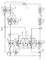
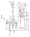
- FIG. 1 shows the configuration of a magnetic disk drive
- the reference numerals/symbols denotes the portions as follows: 1 for a magnetic disk; 2 for a compound magnetic head including write and read heads; 3 for a head slider; 4 for a head supporting mechanism; 5 for a positioning mechanism; 51 for a coarse actuator formed of a voice coil motor (VCM); 52 for a fine actuator formed of a microactuator (MA) including a piezoelectric device (PZT device); 6 for a positioning control unit; 7 for a spindle motor; 8 for a rotational axis; 10 for a housing; 60 for a head-position detecting unit; 61 for a state predicting unit; 62 for a fine control unit; 63 for a coarse control unit; 64 for a fine drive unit; 65 for a coarse drive unit; 66 for a driving-signal limiting unit 66; 1000 for
- the compound head 2 is configured to include a read head and a write head.
- the read head is formed of a GMR head (giant magnetoresistive head) using a GMR effect
- the write head is formed of an inductive magnetic head.
- These heads are mounted to the head slider 3.
- the state predicting unit 61 is configured as a mathematical model for the fine actuator 52, which is formed of the VCM, and the fine actuator 52, which is formed of the MA. That is, the state predicting unit 61 includes a VCM-state predicting unit 611 and an MA-state predicting unit 612.
- the head supporting mechanism 4 supports the head slider 3, and therethrough supports the compound-type magnetic head 2 so that it opposes the disk 1.
- the coarse actuator 51 drives the head supporting mechanism 4 to rotate about the rotational axis 8 as the center, the compound-type magnetic head 2 is moved together with the fine actuator 52.
- the fine actuator 52 is disposed between the head supporting mechanism 4 and the head slider 3.
- the fine actuator 52 thus disposed drives the head slider 3 to position the head 2 on a desired track of the disk 1.
- the coarse actuator 51 performs coarse positioning control of the head 2 to the fine actuator 52, whereas the coarse actuator 51 performs fine positioning control of the head 2 to the desired track.
- embodiments discussed below include those having a plurality of disks 1 and pluralities of individually corresponding heads 2, head sliders 3, fine actuators 52, and head supporting mechanisms 4. In this configuration, the coarse actuator 51 moves the plurality of head supporting mechanism 4 in batches.
- Control is performed such that the head 2 is moved on the disk 1 according to a dual-stage actuator that is formed of the coarse actuator 51 and the fine actuator 52, and the head 2 is positioned on-track according to cooperative operation of the two actuators.
- the read head of the head 2 detects a servo pattern as position information prewritten on the disk 1, and then sends a detected signal indicative of the position information to the head-position detecting unit 60 in the positioning control unit 6.
- the head-position detecting unit 60 detects the current position of the head 2, and feeds it as a head position signal Phd to the fine control unit 62 and the state predicting unit 61.
- the fine control system 1000 is configured of a subtracter 62S, the MA-state predicting unit 612 in the state predicting unit 61 (in the state predicting unit 61 functioning as a state predicting unit for the fine actuator 52), the driving-signal limiting unit 66, and the fine drive unit 64.
- the head position signal Phd is input to the subtracter 62S from the head-position detecting unit 60.
- the subtracter 62S the differential between a desired position signal R and the head position signal Phd is taken out therefrom; and as a result, a position error signal Pe(B) indicative of the differential is fed into the fine control unit 62.
- the fine control unit 62 inputs the position error signal Pe(B) as well as a prediction speed signal Ve(B) and a prediction disturbance signal Fe(B) from the MA-state predicting unit 612 provided in the state predicting unit 61 (refer to FIGS. 2 and 3 ). Then, the predicting unit 612 outputs the signal to the driving-signal limiting unit 66.
- the MA-state predicting unit 612 inputs the head position signal Phd from the head-position detecting unit 60 and a fine control signal C(B) used as a feedback element from the fine control unit 62. According to the two signals, the MA-state predicting unit 612 predicts disturbances (such as force disturbances and positional disturbances) that will be imposed on the movement speed of the head 2 and on the head 2. Then, the MA-state predicting unit 612 calculates a prediction displacement signal Xe(B), a prediction speed signal Ve(B), and a prediction disturbance signal Fe(B) associated with the fine actuator 52.
- disturbances such as force disturbances and positional disturbances
- the MA-state predicting unit 612 outputs a prediction speed signal Ve(B) and the prediction disturbance signal Fe(B) to the fine control unit 62, and outputs a prediction displacement signal Xe(B) to an adder 61A.
- the adder 61A performs the addition of the prediction displacement signal Xe(B) associated with the fine actuator 52 to a prediction displacement signal Xe(S) associated with the coarse actuator 51, calculates a total prediction displacement signal Xe, and outputs the signal to a subtracter 61S.
- the subtracter 61S generates a prediction position error signal Phd0 obtained through subtraction of the total prediction displacement signal Xe from the head position signal Phd.
- a compensation signal Phd0' is obtained through multiplication of an MA-state prediction unit gain 612g with the aforementioned prediction position error signal Phd0'.
- the fine control unit 62 multiplies a position-error feedback gain 621, a speed feedback gain 622, and a disturbance-amount feedforward gain 623 with the respective position error signal Pe(B), prediction speed signal Ve(B) and prediction disturbance signal Fe(B). Then, the fine control unit 62 outputs the resultant signals to an adder 62A. Upon receipt, the adder 62A performs the addition of the three signals and outputs the fine control signal C(B) to the driving-signal limiting unit 66 and the MA-state predicting unit 612. The fine control signal C(B) reduces the magnitude of the position error signal Pe(B).
- the fine control unit 62 may be configured such as to multiply individual coefficients of a proportional differentiator (phase lead compensator) and an integrator with the input position error signal Pe(B) and to thereby generate the fine control signal C(B).
- the fine control signal C(B), which has been output from the fine control unit 62, is not directly fed into the fine drive unit 64, but is beforehand fed into the driving-signal limiting unit 66.
- the driving-signal limiting unit 66 limits the level of the fine control signal C(B) and generates a real fine control signal C(B) 1 . This is done so as to drive the fine actuator 52 at a threshold that is equal to or lower than a threshold at which the properties of the piezoelectric device (PZT device), which constitutes the fine actuator 52, begins to deteriorate because of erosion caused by electrochemical reaction.
- the fine drive unit 64 Having been input with the real fine control signal C(B) 1 , the fine drive unit 64 generates a fine drive signal u(B), outputs the signal to the fine actuator 52, and thereby controls and drives the fine actuator 52.
- the coarse control system 2000 associated with the coarse actuator 51 is configured of a subtracter 63S, the coarse control unit 63, and the VCM-state predicting unit 611 functioning as a state predicting unit for the fine actuator 51.
- the VCM-state predicting unit 611 in the state predicting unit 61 predicts the current position of the head 2 according to the head position signal Phd received from the head-position detecting unit 60, and outputs a prediction displacement signal Xe(S) to the coarse control unit 63.
- the prediction displacement signal Xe(S) which has been fed to the coarse control unit 63 from the VCM-state predicting unit 611, is output to the subtracter 63S before being input to the coarse control unit 63.
- the VCM-state predicting unit 611 predicts disturbances (such as force disturbances and positional disturbances) that will be imposed on the movement speed of the head 2 and on the head 2 according to a fed-back compensation signal Phd0" and the coarse control signal C(S) received from the coarse control unit 63.
- the VCM-state predicting unit 611 calculates a prediction displacement signal Xe(S), a prediction speed signal Ve(S), and a prediction disturbance signal Fe(S) that are associated with the fine actuator 51. Thereafter, the VCM-state predicting unit 611 outputs the prediction displacement signal Xe(S) and the prediction disturbance signal Fe(S) to the coarse control unit 63, and outputs the prediction displacement signal Xe(S) to the adder 61A.
- the state predicting unit 61A operates similarly as in the preceding case.
- the adder 61A performs the addition of the prediction displacement signal Xe(B) associated with the fine actuator 52 to a prediction displacement signal Xe(S) associated with the coarse actuator 51, calculates a total prediction displacement signal Xe that is associated with to the fine actuator 52 and the coarse actuator 51, and then outputs the signal to a subtracter 61S.
- the subtracter 61S operates similarly in the preceding case. That is, the subtracter 61S generates a prediction position error signal Phd0 obtained through subtraction of the total prediction displacement signal Xe from the head position signal Phd.
- the compensation signal Phd0" is obtained through multiplication of a VCM-state prediction unit gain 613g with the aforementioned prediction position error signal Phd0.
- a position-error feedback gain 631, a speed feedback gain 632, and a disturbance-amount feedforward gain 633 are multiplied with the compensation relative displacement signal Pe(S), the prediction speed signal Ve(S), the prediction disturbance signal Fe(S), respectively. Thereafter, these individual signals are added in an adder 63A; and as a result, a coarse control signal C(S) for controlling the compensation relative displacement signal Pe(S) to be close to zero is calculated.
- the coarse control signal C(S) is then output to the coarse drive unit 65, and is fed back to the VCM-state predicting unit 611.
- the arrangement may be made such that the coarse control signal C(S) is provided to the VCM-state predicting unit 611 so as to be feed forwarded thereto.
- the coarse control unit 63 may be configured so as to multiply individual coefficients of a proportional differentiator (phase lead compensator) and an integrator with the input compensation relative displacement signal Pe(S) to thereby generate the coarse control signal C(S).
- the coarse drive unit 65 Having been input with the coarse control signal C(S), the coarse drive unit 65 generates a coarse drive signal u(S), outputs the signal to the coarse actuator 51, and thereby controls and drives the coarse actuator 51.
- each of the actuator control systems carries out the operation sequences described above.
- the head slider 3 is supported to the head supporting mechanism 4 via a flexure 9 (flexible printed circuit board), and the fine actuator 52 is provided drivable on the flexure 9.
- the fine actuator 52 is formed of a pair of subactuators 52a and 52b.
- Each of the subactuators 52a and 52b is formed of an upper electrode 521, an piezoelectric device 522, and a lower electrode 523.
- the two piezoelectric devices are driven in a push-pull manner, and the amount of deformation of the individual piezoelectric devices is converted by an expansion mechanism into the amount of displacement of the head 2.
- the head slider 3 rotationally moves on a pivot in the center, and the head 2 is pivotably moved. In this configuration, the center of gravity and the center of rotational movement are aligned with each other.
- the piezoelectric device is formed of a PZT device.
- the PZT device is a typical device formed of a ceramic piezoelectric material, and it is expressed using chemical symbols as follow: Pb(Zr,Ti)O 3 (1)
- the PZT device is produced according to a sintering method that includes a powdering step and a sintering step.
- a thin-film PZT device is deposited according to, for example, sol-gel techniques, sputtering techniques, or CVD (chemical vapor deposition) techniques.
- PZT thin-film is expressed by the following composition formula: ⁇ Pb(Zr 0.53 Ti 0.47 ) ⁇ 0.8 + (Pb0) 0.2 (2)
- the ratio of Zr : Ti is 53 : 47
- lead oxide (PbO) is excessively included by 20%.
- electrochemical reaction is caused by moisture permeating through the device during the processing or by moisture permeating through the device in the atmospheric environment during operation.
- the lead oxide (PbO) chemically reacts as follows:
- Pt electrodes are disposed on two sides of the PZT device, and voltage is applied to the electrodes.
- the electrochemical reaction including precipitation of lead at the anodic side and the cathodic side is expressed by the following chemical formulas:
- the water electrolysis (electrochemical reaction) is expressed as follows:
- lead is ionized by hydroxyl ions caused in the water electrolysis.
- lead ions precipitates in the cathodic electrode.
- the chemical reaction such as lead precipitation or electrolysis is characterized in that the reaction is abruptly accelerated at the voltage level exceeding a voltage threshold.
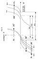
- FIG. 8 shows the relationship between the voltage (potential difference) applied in the electrochemical reaction and the current flowing through the PZT device during the reaction.
- the reaction advances at a potential difference V1 or higher, and the current flowing through the device greater increases in proportion to the advancement of electrolysis.
- the electric potential at which the reaction advances is generally called “theoretical decomposition voltage" of lead.
- the theoretical decomposition voltage is 0.572 V at the events of the reactions shown by Formulas (5) and (6), and is 1.229 V at the events of the reactions shown by Formulas (8) and (9).
- the potential difference V1 is indicative of the theoretical decomposition voltage of lead
- a potential difference V2 is indicative of the theoretical decomposition voltage of water.
- oxygen overvoltage needs to be added to the theoretical decomposition voltage to cause the electrolysis to advance and to generate oxygen. That is, the electrochemical reaction advances according to the application of the added voltages of the theoretical decomposition voltage and the oxygen overvoltage.
- the oxygen overvoltage is ranged from 0.37 to 0.47 V.
- the voltage value at which the reactions expressed by the Formulas (5) and (6) is expressed by the following expression: 0.527 + 0.37 to 0.47 ⁇ 0.97 to 1.0 V
- the voltage value at which the reactions expressed by the Formulas (8) and (9) is expressed by the following expression: 1.229 + 0.37 to 0.47 ⁇ 1.6 to 1.7 V
- the lead-precipitating electrochemical reaction almost does not advance at 1 V or lower.
- the influence in the atmospheric environment is accelerated according to the water electrolysis, whereas the lead-precipitating electrochemical reaction almost does not advance.
- the electrode positive/negative polarities keep altering depending on the magnetic head position
- lead Pb precipitates at the two sides.
- the PZT device has a small thickness on the order of ⁇ m.
- the precipitated lead Pb causes short-circuiting and hence breakdown of the PZT device.
- the threshold voltages exist at which the chemical reaction between the lead Pb and the water electrolysis are the same in the qualitative aspect, and decomposition reaction is not caused (not accelerated).
- there exist threshold voltages at which properties of the PZT device are within ranges that assures the lead Pb precipitation amount and chemical reaction speed as properties of the PZT device.
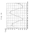
- FIG. 9 shows the relationship between a voltage V [V] and a current I [ ⁇ A] when voltage is applied to the PZT device of the fine actuator.
- the horizontal axis represents the application voltage
- the vertical axis represents the current flowing through the PZT device.
- the current flowing through the PZT device sharply increases in the vicinity of an application voltage of 50 V.
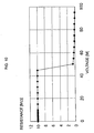
- FIG. 10 shows the relationship between the application voltage and the electrical resistance value R in the state shown in FIG. 9 .
- the electric resistance of the 10 M ⁇ is reduced to a level of 70 to 100 k ⁇ .
- the resistance value abruptly decreases.
- the arrangement should be made such that the PZT-device using fine actuator is driven in a voltage range that is not higher than the voltage corresponding to the abrupt electric-resistance changing point.
- this arrangement enables the prevention of short-circuiting in the PZT device as well as the breakdown of the fine actuator.
- the electric-resistance changing point is variable depending on the layer quality and the film thickness of the PZT device.
- the dependency to the layer quality is a matter relevant to the fabrication. However, to handle the matter regarding the dependency to the film thickness, the properties thereof need to be understood to arrange the driving system.
- V an electrofield
- a safety factor of 0.2 is multiplied with a tolerance application voltage, the bias voltage is set to 0 V which is equal to or lower than the decomposition voltage, and the threshold of the application voltage is set to ⁇ 10 V. Specifically, under these conditions, the current can be used by controlling it so as to be equal to or lower than 1 ⁇ A. This arrangement enables the prevention of breakdown of the fine actuator and short-circuiting in the piezoelectric device.
- the fine actuator constituted of the PZT device is driven and controlled by the driving-signal limiting unit 66 at voltages that is equal to or lower than the above-described threshold (decomposition voltage) or the vicinity thereof.
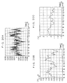
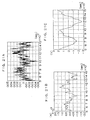
- FIGS. 12 show simulation results of an embodied example according to the present embodiment. Conditions of the simulation are as follows: Rotational speed: 12,000 r/min Track density: 45,000 track/inch Track pitch: 0.56 ⁇ m Sampling frequency: 20 kHz Servo band: 1.5 kHz Threshold for the driving-signal limiting unit: 1.2 V
- FIGS. 12A to 12D each shows a simulation experiment result performed using a configuration in which a servo loop of a microactuator includes the driving-signal limiting unit 66.
- FIGS. 12A and 12B each shows the simulation experiment result at a track jump event; specifically, FIG. 12A shows head positions (position errors), and FIG. 12B shows driving voltages for the fine actuator 52 at that event.
- FIGS. 12C and 12D each shows the simulation experiment result at a track following event; specifically, FIG. 12C shows head positions (position errors), and FIG. 12D shows driving voltages applied to the fine actuator 52 at that event.
- the simulation results teach the following.
- the magnetic disk drive of the present embodiment at a track jump event, when head position errors converge to zero, also displacements of the fine actuator 52 converge to zero.
- FIG. 12B under the condition where 3.6 V is set to the threshold for the driving voltage for the fine actuator 52, 3.6 V is applied for 0.4 msec. However, the voltage decreases thereafter, keeping decreasing to 1 V or lower after 0.7 msec has passed.
- the position error such that a 10% track pitch is on-tracked.
- the driving voltage for the fine actuator 52 is limited to 0.5 V or lower, the head 2 is positioned stable.
- the positioning accuracy can be maintained stable.
- a group of steps (1) to (3) and a group of steps (4) to (6) may be processed in the form of parallel processing to synchronously proceed.
- the two groups may be processed in the form of sequential processing to precede one of them.
- the above-described head-positioning control method is thus capable of solving the problem of property deterioration of the piezoelectric device that can occur because of a high-level drive signal.
- the head-positioning control method is capable of maintaining the function of high-speed and high-accuracy positioning the head on a desired track for a long time. Consequently, the head-positioning control method effectively operates for the implementation of a high-record-density disk drive unit.
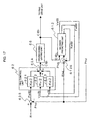
- a property inspecting unit 67 and a limitation-voltage modifying unit 68 is additionally provided.
- the property inspecting unit 67 measures the relationship between the voltage output from the fine drive unit 64 to the fine actuator 52 and the current flowing to the piezoelectric device of the fine actuator 52, and performs inspection for existing of an overcurrent.
- the limitation-voltage modifying unit 68 modifies the threshold set in the driving-signal limiting unit 66 according to the inspection result obtained by the property inspecting unit 67.
- Io 1 ⁇ 10 -1 [ ⁇ A]
- the current flowing at a voltage higher than the decomposition voltage increases one hundred times or higher on the order.
- the decomposition voltage is theoretically constant while it depends on the material. In practice, however, there are individuality variations in property including, for example, oxygen-overvoltage variations and composition variations. As such, the threshold of the driving voltage needs to be regulated for each fine actuator.
- the displacement property of the fine actuator 52 deteriorates when the electrochemical reaction is accelerated because of the flow of a current that is higher than the intra-piezoelectric-device current Io by a predetermined multiple (for example, 10) thereof.
- the property inspecting unit 67 detects current flowing through a driving circuit by using a detection resistance, derives the value of the current flowing in the piezoelectric device from a detected voltage value, and compares it with the value of the current Io. If the value of the current Io is greater than the aforementioned predetermined multiple (for example, 10), the limitation-voltage modifying unit 68 reduces the threshold voltage set in the driving-signal limiting unit 66 by 0.1 (V). These operations are iterated, thereby preventing the property deterioration of the fine actuator 52.
- the additional provision of the limitation-voltage modifying unit 68 enables the positioning accuracy to be maintained stable while limiting the application voltage for the fine actuator 52.
- a group of steps (1) to (3) and a group of steps (4) to (6) may be processed in the form of parallel processing to synchronously proceed.
- the two groups may be processed in the form of sequential processing to precede one of them.
- the above-described head-positioning control method is thus capable of implementing the control of the head actuators with high accuracy regardless of individuality variations in properties of the piezoelectric devices and humidity variations in the use environment, particularly, humidity variations.
- a third embodiment of the invention will be described with reference to FIG. 14 .
- the same reference numeral/symbols are used to refer to the same configuration members as those of the first embodiments shown in the FIG. 1 .
- a time function filter 69 is additionally provided.
- the time function filter 69 limits the time during which outputs are continually produced.
- the function of the time function filter 69 is provided as a countermeasure against the permeation of moisture. Since the current value increases as electroconductive time passes, when a driving voltage higher than or equal to the threshold is applied, a continuous drive output time is limited.
- the time function filter 69 When performing positioning control for the head 2 in, for example, in a settling mode or a truck jump mode, the time function filter 69 operates according to a driving voltage that increases higher than or equal to a decomposition voltage of 2.2 V. As such, the time function filter 69 is provided to function such that when the driving voltage is higher than or equal to 4 V, the time is set equal to or less than 200 ⁇ sec. Similarly, when the driving voltage is higher than or equal to 3 V and lower than 4 V, the time is set the time is set equal to or less than 400 ⁇ sec; and when the driving voltage is higher than or equal to 2 V and lower than 3 V, the voltage is set equal to or less than 500 ⁇ sec. Thereby, the current flowing into the piezoelectric device can be prevented from being abruptly increased because of the electrolysis. In this way, the additional provision of the time function filter 69 enables the positioning accuracy to be maintained stable while limiting the application voltage for the fine actuator 52.
- the present embodiment has been described with reference to the example case where the decomposition voltage is 2.2 V.
- the threshold of the application voltage may be ⁇ 10 V, as described in the first embodiment with reference to FIGS. 6 to 11 .
- effects similar effects can be obtained.
- the time function filter 69 has been described with reference to the case of functioning in four stages depending on the individual driving voltage values.
- the time function filter 69 may be arranged to work in an arbitrary number of stages as long as being capable of limiting the continuous output time to thereby prevent the current flowing into the piezoelectric device from being increased.
- a group of steps (1) to (3) and a group of steps (4) to (6) may be processed in the form of parallel processing to synchronously proceed.
- the two groups may be processed in the form of sequential processing to precede one of them.
- the above-described head-positioning control method is thus capable of implementing the control of the head actuators with high accuracy regardless of variations in the command-driving voltage.
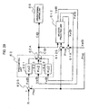
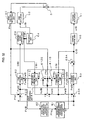
- the reference numerals/symbols denotes the portions as follows: 1 for a magnetic disk; 2 for a magnetic head, 3 for a head slider; 4 for a head supporting mechanism; 5 for a positioning mechanism; 51 for a coarse actuator; 52 for a fine actuator formed of a microactuator (MA) including a piezoelectric device (PZT device); 6 for a positioning control unit; 7 for a spindle motor; 8 for a rotational axis; 10 for a housing; 60 for a head-position detecting unit; 61 for a state predicting unit; 62 for a fine control unit; 63 for a coarse control unit; 64 for a fine drive unit; 65 for a coarse drive unit; 66 for a driving-signal limiting unit 66; 1000 for a fine control system configured inclusive of the fine control unit 62, the fine drive unit 64, and the driving
- the fine control signal C(B) is directly fed back from the fine control unit 62 to the MA-state predicting unit 612 of the state predicting unit 61.
- a real fine control signal C(B) 1 is fed back to the MA-state predicting unit 612 from the fine control unit 62.
- the MA-state predicting unit 612 inputs a head position signal Phd from the head-position detecting unit 60 and the real fine control signal C(B) 1 from the fine control unit 62. According to the two signals, the MA-state predicting unit 612 predicts disturbances (such as force disturbances and positional disturbances) that will be imposed on the movement speed of the head 2 and on the head 2.
- the MA-state predicting unit 612 calculates a prediction displacement signal Xe(B), a prediction speed signal Ve(B), and a prediction disturbance signal Fe(B) associated with the fine actuator 52. Thereafter, the MA-state predicting unit 612 outputs a prediction speed signal Ve(B) and the prediction disturbance signal Fe(B) to the fine control unit 62, and outputs a prediction displacement signal Xe(B) to a subtracter 612S.
- the subtracter 612S subtracts the prediction displacement signal Xe(B) from the head position signal Phd, thereby calculates a compensation position signal Phd 1 , and feeds the compensation head position Phd 1 back to the MA-state predicting unit 612.
- the fine control unit 62 multiplies a position-error feedback gain 621, a speed feedback gain 622, and a disturbance-amount feedforward gain 623 with the respective position error signal Pe(B), the individual prediction speed signal Ve(B), and prediction disturbance signal Fe(B). Then, these signals are added by the adder 62A, and a fine control signal C(B) for making the position error signal Pe(B) to be close to zero is calculated, and is output to the driving-signal limiting unit 66.
- the fine control unit 62 may be configured such as to multiply individual coefficients of a proportional differentiator (phase lead compensator) and an integrator with the input position error signal Pe(B) and to thereby generate the fine control signal C(B).
- the fine control signal C(B), which has been output from the fine control unit 62, is not directly fed into the fine drive unit 64, but is beforehand fed into the driving-signal limiting unit 66.
- the driving-signal limiting unit 66 limits the level of the fine control signal C(B) and generates a real fine control signal C(B) 1 . This is done so as to drive the fine actuator 52 at a voltage that is equal to or lower than a threshold at which the properties of the piezoelectric device (PZT device), which constitutes the fine actuator 52, begins to deteriorate because of erosion caused by electrochemical reaction.
- the fine drive unit 64 Having been input with the real fine control signal C(B) 1 , the fine drive unit 64 generates a fine drive signal u(B), outputs the signal to the fine actuator 52, and thereby controls and drives the fine actuator 52.
- the real fine control signal C(B) 1 which has been output to the driving-signal limiting unit 66, is fed back to the MA-state predicting unit 612.
- the VCM-state predicting unit 611 in the state predicting unit 61 predicts the current position of the head 2 according to the head position signal Phd received from the head-position detecting unit 60, and outputs a prediction displacement signal Xe(S).
- the VCM-state predicting unit 611 predicts disturbances (such as force disturbances and positional disturbances) that will be imposed on the movement speed of the head 2 and on the head 2 according to a fed-back compensation head position Phd 2 and the coarse control signal C(S) received from the coarse control unit 63. Then, the VCM-state predicting unit 611 calculates a prediction displacement signal Xe(S), a prediction speed signal Ve(S), and a prediction disturbance signal Fe(S) that are associated with the fine actuator 51.
- disturbances such as force disturbances and positional disturbances
- the VCM-state predicting unit 611 outputs the prediction displacement signal Xe(S) and the prediction disturbance signal Fe(S) to the coarse control unit 63, and outputs the prediction displacement signal Xe(S) to the subtracter 611S.
- the subtracter 611S subtracts the prediction displacement signal Xe(S) from the head position signal Phd, calculates the compensation head position Phd 2 , and feeds the compensation head position Phd 2 back to the VCM-state predicting unit 611.
- the disturbance compensating unit 81 generates a disturbance error signal Q and outputs the signal.
- the disturbance error signal Q corresponds to a positional deviation occurring because of a rotationally-synchronous disturbance attributable to, for example, the eccentricity of the disk 1.
- An adder 81A performs the addition of the disturbance error signal Q, which has been received from the disturbance compensating unit 81, to the prediction displacement signal Xe(S), which has been received from the VCM-state predicting unit 611. The result is output as a compensation relative displacement signal Phd 3 .
- a differential between the desired position signal R and the compensation relative displacement signal Phd 3 is taken out, and is fed as a compensation relative displacement signal Pe(S) into the coarse control unit 63.
- a position-error feedback gain 631, a speed feedback gain 632, and a disturbance-amount feedforward gain 633 are multiplied with the compensation relative displacement signal Pe(S), the prediction speed signal Ve(S), the prediction disturbance signal Fe(S), respectively. Thereafter, these individual signals are added in an adder 63A; and as a result, a coarse control signal C(S) for controlling the compensation relative displacement signal Pe(S) to be close to zero is calculated.
- the coarse control signal C(S) is then output to the coarse drive unit 65, and is fed back to the VCM-state predicting unit 611.
- the arrangement may be made such that the coarse control signal C(S) is provided to the VCM-state predicting unit 611 so as to be feed forwarded thereto.
- the coarse control unit 63 may be configured so as to multiply individual coefficients of a proportional differentiator (phase lead compensator) and an integrator with the compensation relative displacement signal Pe(S) to thereby generate the coarse control signal C(S).
- the coarse drive unit 65 Having been input with the coarse control signal C(S), the coarse drive unit 65 generates a coarse drive signal u(S), outputs the signal to the coarse actuator 51, and thereby controls and drives the coarse actuator 51.
- the coarse control unit 63 performs a calculation of a coarse control amount from the position error, which is a difference between a prediction amount of the amount of a head movement amount associated with the coarse actuator 51 and a desired position, and a prediction amount received from the VCM-state predicting unit 611 in the state predicting unit 61. This calculation is the same as a calculation of a position error between a desired position and a head movement amount of the fine actuator 52. To the aforementioned position error, there is added an amount of displacement, namely, the disturbance error signal Q that has been output from the disturbance compensating unit 81, for offsetting the position error caused by rotationally-synchronous disturbances.
- the addition result is used as a compensated relative displacement signal, namely, the compensation relative displacement signal Pe(S), for the coarse control unit 63.
- the output of the disturbance compensating unit 81 may be used as an eccentricity amount learned in the step of manufacture or initial activation, that is, as a value representing the amount of a position error caused by rotationally-synchronous disturbances.
- each of the actuator control systems carries out the operation sequence described above.
- the positioning control is performed such that the fine actuator 52 functions to converge the error between the current position and the desired position of the head 2 to zero, the coarse actuator 51 functions to converge the head movement amount of the fine actuator 52 to zero, and consequently, the position error between the desired position and the head movement amount associated with the fine actuator 52 is converged to zero.
- the fine actuator 52 is driven and controlled at a low driving voltage in the vicinity of the center of the operation range, thereby improving the positioning performance.
- a position error due to disturbances synchronous with the disk rotation is large.
- the driving voltage exceeds the threshold voltage.
- the position error due to the disturbances synchronous with the disk rotation is compensated for by using the coarse control unit 63 and the coarse actuator 51 according to the disturbance compensating unit 81.
- the positioning accuracy is improved while the fine actuator 52 is driven and controlled in a fine range.
- the output to the fine actuator 52 is set below the threshold voltage at which electrochemical reaction of the piezoelectric device is accelerated.
- the coarse actuator 51 is used to compensate for low-frequency rotationally-synchronous disturbances causing a large position error.
- the driving-signal limiting unit 66 is used to rotate and control the fine actuator 52, which is constituted of the PZT device, at a voltage that is below the threshold voltage.
- FIGS. 19 to 21 individually show simulation results of an embodied example according to the present embodiment. Conditions of the simulation are as follows: Rotational speed: 12,000 r/min Track density: 45,000 track/inch Track pitch: 0.56 ⁇ m Sampling frequency: 20 kHz Servo band: 1.5 kHz Threshold for the driving-signal limiting unit: 1.2 V
- FIG. 19 shows a time response of a rotationally-synchronous disturbance.
- the warpage width is shown as 0.7 ⁇ m.
- FIGS. 20A to 20C each show a case where, under the conditions of the present embodiment, the servo loop of the fine actuator 52 includes the driving-signal limiting unit 66, and the servo loop of the coarse actuator 51 includes the disturbance compensating unit 81.
- FIGS. 21A to 21C each show the case of a controlling-and-driving method for a comparison example including neither the driving-signal (voltage) limiting unit nor the disturbance compensating unit.
- FIGS. 20A and 21A each show a head-position error signal at a track-following event;
- FIGS. 20B and 21B each show a driving current for the coarse actuator 51 at the aforementioned event;
- FIGS. 20C and 21C each show a driving for the fine actuator 52 at the aforementioned event.
- the simulation results will be described.
- a 10% track pitch is on-tracked in the track-following event.
- the driving voltage is equal to or lower than 1 V in the present embodiment shown in FIG. 20C .
- the driving voltage is 2.5 V at maximum in the comparison example shown in FIG. 21C .
- FIGS. 20B and 21B while the driving currents of the coarse actuator 51 are substantially the same, phases with respect to the driving voltages of the fine actuator 52 are different from each other. In each of these cases, a positioning accuracy of within a 10% track pitch is achieved; however, in the comparison example, the driving voltage for the fine actuator 52 is high.
- the phase of the driving current is negative with respect to the driving voltage.
- control bands of the fine actuator and the coarse actuator are different from each other; that is, the phase of the fine actuator driven in a high band is different from the phase of the coarse actuator driven in a low band.
- the relative operations for compensating for rotationally-synchronous disturbances result in force disturbances.
- the present embodiment additionally including the disturbance compensating unit 81 enables the fine actuator 52 and the coarse actuator 51 to operate in the same phase.
- the fine actuator 52 and the coarse actuator 51 operates harmonic, thereby compensating for the rotationally-synchronous disturbances as unidirectional position errors. Consequently, even when the fine actuator 52 is driven in a low voltage, high-accuracy head positioning can be implemented.
- the coarse control system 2000 compensates for the rotationally-synchronous disturbances.
- the load of the piezoelectric device in the fine actuator 52 is reduced.
- the level of the drive signal for the piezoelectric device is limited equal to or lower than the threshold at which property deterioration occurs in the piezoelectric device because of erosion caused by the electrochemical reaction.
- the properties are not deteriorated.
- high-speed and high-accuracy head poisoning on a desired track can be maintained for a long time. Consequently, the embodiment effectively operates for the implementation of a high-record-density disk drive unit.
- a group of steps (1) to (3) and a group of steps (4) to (6) may be processed in the form of parallel processing to synchronously proceed.
- the two groups may be processed in the form of sequential processing to precede one of them.
- the above-described head-positioning control method is thus capable of solving the problem of property deterioration of the piezoelectric device that can occur because of a high-level drive signal.
- the head-positioning control method is capable of maintaining the function of high-speed and high-accuracy positioning the head on a desired track for a long time. Consequently, the head-positioning control method effectively operates for the implementation of a high-record-density disk drive unit.
- an error measuring unit 82 is disposed in the stage subsequent to the head-position detecting unit 60, and a disturbance compensating unit 81 is disposed in the stage subsequent to the error measuring unit 82.
- the error measuring unit 82 calculates the amount of a position error attributed to disturbances that is synchronous with the disk rotation according to the head position signal Phd, thereby generates a compensation position error signal Phd 5 , and feeds the signal to the disturbance compensating unit 81.
- the disturbance compensating unit 81 According to the received compensation position error signal Phd 5 , the disturbance compensating unit 81 generates a compensation-dedicated disturbance-controlling signal Q 1 and outputs it. Then, an adder 73A performs the addition of a coarse control signal C(S) received from the coarse control unit 63 to the disturbance-controlling signal Q 1 received from the disturbance compensating unit 81. A compensation coarse control signal C(S) 1 generated through the addition is fed to the coarse drive unit 65, and is also fed back to the VCM-state predicting unit 611 in the state predicting unit 61.
- a compensation regulating unit 83 is additionally provided.
- the compensation regulating unit 83 weights an input disturbance error signal Q for the fine control unit 62 and the coarse control unit 63.
- a fine position error signal Q(B) and a coarse position error signal Q(S) are distributed to the control units 62 and 63, respectively.
- the signals are output to an adder 74A on the side of the fine control unit 62 and to an adder 75A on the side of the coarse control unit 63.
- the fine position error signal Q(B) is added to the head position signal Phd, and a compensation position error signal Phd 6 is thereby generated.
- the coarse position error signal Q(S) is added to the compensation relative displacement signal Phd 3 , and a compensation position error signal Phd 7 is thereby generated.
- Other portions and operations of the configuration are similar to those in the fourth embodiment; hence, descriptions thereof are omitted herefrom.
- the piezoelectric device can be protected from property deterioration attributable to an excessively high drive signal level.
- a seventh embodiment of the invention will be described with reference to FIG. 24 .
- the same reference numeral/symbols are used to refer to the same configuration members as those in the fourth embodiment shown in FIG. 15 .
- a rotational-synchronization error measuring unit 82 is disposed in the stage subsequent to the head-position detecting unit 60
- a rotational-synchronization disturbance compensating unit 81 is disposed in the stage subsequent to the error measuring unit 82
- a synchronous-disturbance compensation regulating unit 83 is disposed in the stage subsequent to the rotational-synchronization disturbance compensating unit 81.
- the error measuring unit 82 calculates the amount of a position error attributed to disturbances synchronous with the disk rotation according to the head position signal Phd, thereby generates a compensation position error signal Phd 5 , and feeds the signal to the disturbance compensating unit 81.
- the disturbance compensating unit 81 According to the received compensation position error signal Phd 5 , the disturbance compensating unit 81 generates a compensation-dedicated disturbance-controlling signal Q 1 and outputs it.
- the compensation regulating unit 83 According to the received disturbance-controlling signal Q 1 , the compensation regulating unit 83 generates a synchronous-disturbance coarse control signal Q(S) 1 and coarse control signal Q(B) 1 .
- an adder 76A performs the addition of a coarse control signal C(S) received from the coarse control unit 63 to the synchronous-disturbance coarse control signal Q(S) 1 received from the disturbance compensating unit 83.
- a compensation coarse control signal C(S) 1 ' generated through the addition is fed to the coarse drive unit 65, and also fed back to the VCM-state predicting unit 611 in the state predicting unit 61.
- an adder 77A performs the addition of a fine control signal C(B) received from the fine control unit 62 to the synchronous-disturbance coarse control signal Q(B) 1 received from the disturbance compensating unit 83.
- a compensation fine control signal C(B)' generated through the addition is fed to the fine drive unit 64 via the driving-signal limiting unit 66, and is also fed back to the MA-state predicting unit 612 in the state predicting unit 61.
- FIG. 25 the same reference numeral/symbols are used to refer to the same configuration members as those in the fourth embodiment shown in FIG. 15 .
- a high-frequency filter 70 is inserted between the fine control unit 62 and the fine drive unit 64, and a low-frequency filter 71 is inserted between the coarse control unit 63 and the coarse drive unit 65.
- the drawing shows a state where a coarse control signal C(S), which has been output from the coarse control unit 63, is input to the coarse drive unit 65 through the low-frequency filter 71 that passes only low-frequency bands.
- the fine control signal C(B) fed from the fine control unit 62 is input to the high-frequency filter 70, and low-band components thereof are cut off.
- the fine control signal C(B) is converted into a fine control signal C(B) 2 condensed into a state corresponding to a disturbance such as mechanical resonance having a relatively small amplitude and a relatively large number of high frequency components, and the fine control signal C(B) 2 is fed into the driving-signal limiting unit 66.
- a cut-off frequency is 600 Hz
- a rotational-synchronization disturbance component of 120 Hz is compressed to 1/5 thereof.
- the amount of compensation for the disturbance of a rotational synchronous primary component or a steady-deviation is made small, and the command voltage to a fine actuator is made small.
- the fine control signal C(B) fed from the fine control unit 62 is input to the low-frequency filter 71, and high frequency components thereof are cut off.
- the fine control signal C(B) is converted into a coarse control signal C(S) 2 condensed into a state corresponding to a disturbance having a relatively large amplitude and a relatively large number of low frequency components, and the coarse control signal C(S) 2 is fed into the coarse drive unit 65.
- a cut-off frequency is 6,000 Hz
- a high-band disturbance component of, for example, a mechanical resonance is significantly reduced.
- the bands to be compensated for are thus separately processed. Thereby, the amount of displacement can be reduced using the fine actuator, and the driving voltage can be reduced equal to or lower than the decomposition voltage.
- Other portions and operations of the configuration are similar to those in the fourth embodiment; hence, descriptions thereof are omitted herefrom.
- a ninth embodiment of the invention will be described with reference to FIG. 26 .
- the steady-deviation compensation regulating unit 72 inputs a steady-deviation fine compensation signal C(B) 2 , which is fed from the fine control unit 62 and which is associated with the fine control signal.
- the compensation regulating unit 72 inputs a steady-deviation coarse compensation signal C(S) 2 , which is fed from the fine control unit 63 and which is associated with the coarse control signal C(S).
- the compensation regulating unit 72 weights the signals for distribution to the fine control system 1000 and the coarse control system 2000. Thereby, the compensation regulating unit 72 generates a steady-deviation fine compensation signal C(B) 3 and a steady-deviation coarse compensation signal C(S) 3 , and outputs the signals. Subsequently, an adder 78A performs the addition of the fine control signal C(B) to the steady-deviation fine compensation signal C(B) 3 . A compensation fine control signal C(B)' generated through the addition is output to the driving-signal limiting unit 66, and is also fed back to the MA-state predicting unit 612 in the state predicting unit 61.
- an adder 79A performs the addition of the coarse control signal C(S) to the steady-deviation coarse compensation signal C(S) 3 .
- a compensation coarse control signal C(S)' generated through the addition is fed to the coarse drive unit 65, and is also fed back to the VCM-state predicting unit 611 in the state predicting unit 61.
- the rotational-synchronization disturbance compensating unit 81 may be configured as that shown in FIG. 22 (fifth embodiment). Also with this configuration, similar advantages can be obtained. Other portions and operations of the configuration are similar to those in the fourth embodiment; hence, descriptions thereof are omitted herefrom.
- the actuator is disposed on a suspension.
- the fine actuator and the coarse actuator independently include the state predicting units.
- the threshold of the driving-signal limiting unit 66 may be set variable depending on the time of operation for which the performance deterioration speed and reliability are required.
- the threshold may be set variable depending on the mode of an operation, such as a seeking operation or a track following operation.
- the MA-state predicting unit 612 outputs the prediction displacement signal Xe(B), generated through calculations, to the 61A.
- the VCM-state predicting unit 611 outputs the prediction displacement signal Xe(S), generated through calculations, to the adder 61A.
- the adder 61A performs the addition of the prediction displacement signal Xe(B) to the prediction displacement signal Xe(S), thereby generates a prediction head position signal Phde (corresponding to Xe in FIG.
- the configuration shown in FIGS. 27 and 28 may be replaced with the configuration shown in FIGS. 31 and 32 .
- the rotational-synchronization error measuring unit 82 In a case of directly compensating for a rotational synchronization error, the rotational-synchronization error measuring unit 82 generates a compensation position signal Phd 5 according to the input head position signal Phd, and outputs the compensation position signal Phd 5 .
- the compensation position error signal Phd 5 corresponds to a positional deviation of the head 2 that is caused by a disk-rotation synchronization disturbance that is attributable to, for example, the eccentricity of the disk 1.
- the rotational-synchronization disturbance compensating unit 81 outputs a disturbance error signal Q as a signal corresponding to the amount of compensation according to the compensation position error signal Phd 5 received from the error measuring unit 82.
- the disturbance error signal Q is then added by an adder 80A to a coarse control signal C(S).
- the output of the disturbance compensating unit 81 may be used as an eccentricity amount learned in the step of manufacture or initial activation, that is, as a value representing the amount of a position error caused by rotational synchronization disturbances.
- the threshold of the driving-signal limiting unit 66 was set to 5 V, and the offset voltage was to 0 V, they may be set so that the current flowing through the piezoelectric device becomes equal to or lower than 5 ⁇ A.
- the threshold may be set variable depending on the time of operation for which the performance deterioration speed and reliability are required.
- the threshold may be set variable depending on the mode of an operation, such as a seeking operation or a track following operation.
Landscapes
- Moving Of The Head To Find And Align With The Track (AREA)
- Control Of Position Or Direction (AREA)
Claims (20)
- Verfahren zur Kopfpositionierung für eine Kopfpositionierungsvorrichtung, welches ein zweistufiges Aktuatorverfahren einsetzt und die folgenden Schritte umfasst:- Ausführen einer Positionierungssteuerung für einen Schreib-/Lesekopf (2) zum Zugreifen auf eine Datenspeicherplatte (1) durch Verwendung eines Grobaktuators (51) und eines Feinaktuators (52); wobei der Feinaktuator (52) durch Verwendung einer piezoelektrischen Vorrichtung konfiguriert wird; und- Einstellen eines Pegels eines Ansteuerungssignals, das dem Feinaktuator (52) unter Benutzung der piezoelektrischen Vorrichtung zuzuführen ist, auf einen Wert, der niedriger ist als ein Grenzwert, um einen Ausfall des Feinaktuators und einen Kurzschluss in der piezoelektrischen Vorrichtung zu verhindern;dadurch gekennzeichnet, dass der Grenzwert auf eine Spannung eingestellt ist, bei welcher eine Verschlechterung der Eigenschaften der piezoelektrischen Vorrichtung durch eine elektrochemische Reaktion verursacht wird, und durch Erfassen des Verhältnisses zwischen einer Befehlansteuerungs-Spannung für den Feinaktuator und einem Strom, der durch die piezoelektrische Vorrichtung fließt, mittels einer Eigenschaften-Prüfeinheit (67) der Kopfpositionierungsvorrichtung, sowie Modifizieren eines Grenzwertes der Befehlsansteuerungsspannung gemäß dem Ergebnis der Erfassung mittels einer Grenzspannungs-Modifizierungseinheit (68) der Kopfpositionierungsvorrichtung.
- Verfahren zur Kopfpositionierung nach Anspruch 1, wobei die piezoelektrische Vorrichtung einen elektrischen Widerstand von 1 MΩ oder höher aufweist.
- Verfahren zur Kopfpositionierung nach Anspruch 1, wobei das Verhältnis zwischen einem Spannungspegel V des Ansteuerungssignals für den Feinaktuator (52) und einem Strom 1, der durch die piezoelektrische Vorrichtung fließt, beschrieben wird als V/I > 10e [Ω].
- Verfahren zur Kopfpositionierung nach Anspruch 1, wobei das Verhältnis zwischen einem Spannungspegel V des Ansteuerungssignals für den Feinaktuator (52) und einer Filmdicke t der piezoelektrischen Vorrichtung beschrieben wird als V/t < 2 x 10⁷ [V/m].
- Verfahren zur Kopfpositionierung nach Anspruch 1, wobei der Grenzwert so eingestellt wird, dass die piezoelektrische Vorrichtung bei einem 500-stündigen ununterbrochen Betrieb in einer Umgebung, die eine Temperatur von 85°C und eine Feuchtigkeit von 90% aufweist, einen elektrischen Widerstand von 1 MΩ oder höher beibehält.
- Verfahren zur Kopfpositionierung nach Anspruch 1, wobei- wenn ein Anteil an Kompensation durch den Feinaktuator (52) gleich Null ist, ein spezifischer Wert einer Offsetspannung ausgegeben wird, der bei einer Spannung von Null für die piezoelektrische Vorrichtung oder bei ½ des Grenzwertes liegt; und- wenn der Anteil an Kompensation gleich Null ist, eine positive / negative Spannung entsprechend des Anteils an Kompensation zu der Offsetspannung hinzugefügt wird.
- Verfahren zur Kopfpositionierung nach Anspruch 6, wobei die Offsetspannung in dem Ansteuerungssignal für den Feinaktuator (52) gleich oder geringer ist als eine Wasser-Zersetzungsspannung (einschließlich Null).
- Verfahren zur Kopfpositionierung nach Anspruch 1, wobei eine Lageabweichung des Kopfes von einer gewünschten Spur, die aufgrund einer Störung, die einen vorbestimmten Betriebsbereich des Feinaktuators (52) überschreitet, eintritt, durch den Betrieb des Grobaktuators (51) kompensiert wird.
- Verfahren zur Kopfpositionierung nach Anspruch 1, wobei eine Lageabweichung des Kopfes von einer gewünschten Spur, die aufgrund einer Störung der Rotationssynchronisation der Platte (1), eintritt, durch den Betrieb des Grobaktuators (51) kompensiert wird.
- Kopfpositionierungsvorrichtung, welche umfasst:- einen Grobaktuator (51) und einen Feinaktuator (52) zum Ausführen einer Positionierungssteuerung gemäß einem zweistufigen Aktuatorverfahren für einen Schreib- / Lesekopf (2), der für das Zugreifen auf eine Datenspeicherplatte (1) vorgesehen ist; und- eine Positionierungssteuerungseinheit (6) für die Steuerung des Grobaktuators und des Feinaktuators, wobei:- der Feinaktuator (52) durch die Benutzung einer piezoelektrischen Vorrichtung konfiguriert wird; wobei- die Positionierungssteuerungseinheit aufweist:- ein Grobsteuerungssystem (2000), welche eine Grobansteuerungseinheit (65) zum Ansteuern von zumindest dem Grobaktuator (51) sowie eine Grobsteuerungseinheit (63) zur Steuerung der Grobansteuerungseinheit (65) aufweist, und- ein Feinsteuerungssystem (1000), welche eine Feinansteuerungseinheit (64) zum Ansteuern des Feinaktuators (51) sowie eine Feinsteuerungseinheit (62) zur Steuerung der Feinansteuerungsseinheit (64) aufweist; und wobei- die Kopfpositionierungsvorrichtung ferner eine Ansteuerungssignal-Begrenzungseinheit (66) umfasst, um einen Pegel eines Feinsteuerungssignals, welches von der Feinsteuerungseinheit (62) zu der Feinansteuerungsseinheit (64) gespeist wird, zu begrenzen, so dass der Pegel niedriger ist als ein Grenzwert, um einen Ausfall des Feinaktuators und einen Kurzschluss in der piezoelektrischen Vorrichtung zu verhindern;dadurch gekennzeichnet, dass der Grenzwert auf eine Spannung eingestellt ist, bei welcher eine Verschlechterung der Eigenschaften der piezoelektrischen Vorrichtung durch eine elektrochemische Reaktion verursacht wird, wobei die Kopfpositionierungsvorrichtung ferner umfasst:- eine Eigenschaften-Prüfeinheit (67) zum Erfassen des Verhältnisses zwischen einer Befehlansteuerungs-Spannung für den Feinaktuator und einem Strom, der durch die piezoelektrische Vorrichtung fließt;
und- eine Grenzungsspannungs-Mozifizierungseinheit (68) zum Modifizieren eines Grenzwertes der Befehl-Ansteuerungs-Spannung gemäß dem Ergebnis, welches von der Eigenschaften-Prüfeinheit erfasst wurde.. - Verfahren zur Kopfpositionierung nach Anspruch 10, wobei die piezoelektrische Vorrichtung des Feinaktuators (52) eine Dünnfilm-PZT Vorrichtung ist, welche aus Blei, Zirkon und Titan zusammengesetzt ist.
- Kopfpositionierungsvorrichtung nach Anspruch 10, ferner umfassend einen Zeitfunktionsfilter (69) zum Begrenzen einer Zeit, in welcher die Ansteuerungs-spannung kontinuierlich ausgegeben wird gemäß einer Befehls-Ansteuerungs-Spannung, wenn die Befehls-Ansteuerungs-Spannung für den Feinaktuator (52) mindestens so hoch wie der Grenzwert ist.
- Kopfpositionierungsvorrichtung nach Anspruch 10, wobei die Kopfpositionierungsvorrichtung ferner eine Positionsabweichungs-Separierungseinheit umfasst, um eine Kompensation so zu separieren, dass eine Lageabweichung des Kopfes (2) von einer gewünschten Spur, die aufgrund einer Störung, die einen vorbestimmten Betriebsbereich des Feinaktuators (52) überschreitet, eintritt, durch den Betrieb des Grobaktuators (51) kompensiert wird.
- Kopfpositionierungsvorrichtung nach Anspruch 10, wobei die Kopfpositionierungsvorrichtung ferner eine Störungskompensationseinheit (81) umfasst, um eine Lageabweichung des Kopfes (2) von einer gewünschten Spur, die aufgrund einer Störung der Rotationssynchronisation der Platte (1) eintritt, in dem Grobsteuerungssystem (2000) zu kompensieren.
- Kopfpositionierungsvorrichtung nach Anspruch 14, wobei die Positionierungssteuerungseinheit umfasst:- eine Störungskompensationseinheit (81), die bei einem Spurverfolgungs-Ereignis eine Lageabweichung des Kopfes (2) von einer gewünschten Spur, die aufgrund einer Störung der Rotationssynchronisation der Platte (1), eintritt, kompensiert wird; und- eine Synchronisationsstörung-Kompensationsregulierungseinheit zum individuellen Gewichten von Anteilen der Kompensation, die von der Störungskompensationseinheit für das Grobsteuerungssystem und das Feinsteuerungssystem ausgeführt wird, und anschießenden Bereitstellen von gewichteten Kompensationsanteilen für das Grobsteuerungssystem und das Feinsteuerungssystem.
- Kopfpositionierungsvorrichtung nach Anspruch 14, wobei die Positionierungssteuerungseinheit umfasst:- eine Dauerabweichungs-Kompensationseinheit, die bedingt, dass der Kopf entgegen einer Dauerstörung, insbesondere einer Reibung, der gewünschten Spur folgt; und- eine Dauerabweichungs-Kompensationsregulierungseinheit (72) zum Gewichten eines Outputs der Dauerabweichungs-Kompensationseinheit in jeder der zwei Steuerungseinheiten, mit dem Zweck, dass die Feinsteuerungseinheit nicht einen Steuerwert ausgibt, der bei einem Spurverfolgungs-Ereignis einen Grenzwert überschreitet.
- Kopfpositionierungsvorrichtung nach Anspruch 14, wobei:- das Grobsteuerungssystem (2000) einen Niederfrequenzfilter (71) umfasst, um den Grobaktuator mit einem Wert als Steuerwert auszustatten, welcher durch die Multiplikation einer Gewichtungsfunktion, mit dem Steuerwert erzielt wird, wobei die Gewichtungsfunktion Gewichtungswirkungen in einem Niederfrequenzband aufweist; und- das Feinsteuerungssystem (1000) einen Hochfrequenzfilter (70) umfasst, um den Feinaktuator mit einem Wert als Steuerwert auszustatten, welcher durch die Multiplikation einer Bewertungsfunktion mit dem Steuerwert erzielt wird, wobei die Gewichtungsfunktion Gewichtungswirkungen in einem Hochfrequenzband aufweist.
- Informationsaufzeichnungs- / Wiedergabevorrichtung, welches umfasst:- eine drehbare Datenspeicherplatte (1);- einen Schreib-/Lesekopf (2) zum Zugreifen auf die Platte (1); und- eine Kopfpositionierungsvorrichtung gemäß einem der Ansprüche 10 bis 17, wobei- der Feinaktuator für ein abschließendes Ausrichten des Kopfes von einem Kopf-Haltemechanismus (4) gehalten wird, der durch den Grobaktuator (51) ansteuerbar ist.
- Informationsaufzeichnungs- / Wiedergabevorrichtung nach Anspruch 18,
wobei die Positionierungssteuerungseinheit (6) ausgestaltet ist, durch Einsatz des Grobaktuators (51) eine Lageabweichung des Kopfes (2) von einer gewünschten Spur, die aufgrund einer Störung, die einen vorbestimmten Betriebsbereich des Feinaktuators (52) überschreitet, eintritt, zu kompensieren. - Informationsaufzeichnungs- / Wiedergabevorrichtung nach Anspruch 18,
wobei die Positionierungssteuereinheit (6) ausgestaltet ist, durch Einsatz des Grobaktuators (51) eine Lageabweichung des Kopfes (2) von einer gewünschten Spur, die aufgrund einer Störung der Rotationssynchronisation der Platte (1) eintritt, zu kompensieren.
Applications Claiming Priority (4)
| Application Number | Priority Date | Filing Date | Title |
|---|---|---|---|
| JP2001231435 | 2001-07-31 | ||
| JP2001231435 | 2001-07-31 | ||
| JP2001270162 | 2001-09-06 | ||
| JP2001270162 | 2001-09-06 |
Publications (3)
| Publication Number | Publication Date |
|---|---|
| EP1282115A2 EP1282115A2 (de) | 2003-02-05 |
| EP1282115A3 EP1282115A3 (de) | 2004-05-06 |
| EP1282115B1 true EP1282115B1 (de) | 2013-05-22 |
Family
ID=26619650
Family Applications (1)
| Application Number | Title | Priority Date | Filing Date |
|---|---|---|---|
| EP02016880.3A Expired - Lifetime EP1282115B1 (de) | 2001-07-31 | 2002-07-30 | Kopfeinstellvorrichtung und Informationsaufzeichnungs/-wiedergabegerät |
Country Status (3)
| Country | Link |
|---|---|
| US (1) | US7031099B2 (de) |
| EP (1) | EP1282115B1 (de) |
| CN (1) | CN1271633C (de) |
Families Citing this family (28)
| Publication number | Priority date | Publication date | Assignee | Title |
|---|---|---|---|---|
| US7038877B2 (en) * | 2003-03-12 | 2006-05-02 | Matsushita Electric Idustrial Co., Ltd. | Head positioning apparatus |
| US7274530B2 (en) * | 2003-10-09 | 2007-09-25 | Seagate Technology Llc | Logical mapping for improved head switching between corresponding tracks in a data handling device |
| US7075748B2 (en) * | 2004-11-24 | 2006-07-11 | Hitachi Global Storage Technologies Netherlands B.V. | Disk drive with a dual-stage actuator and failure detection and recovery system for the secondary actuator |
| US7400467B1 (en) * | 2005-10-07 | 2008-07-15 | Maxtor Corporation | Methods and apparatus for managing write inhibit in response to a predictive metric |
| US7538971B2 (en) * | 2006-04-26 | 2009-05-26 | Maxtor Corporation | Microactuator control adjustment using temperature sensor measurements |
| US7460329B2 (en) * | 2006-10-25 | 2008-12-02 | Seagate Technology Llc | Feedforward compensator for induced vibration |
| JP4785148B2 (ja) * | 2007-07-30 | 2011-10-05 | 東芝ストレージデバイス株式会社 | 記憶装置、制御方法及び記憶装置の制御装置 |
| JP4908378B2 (ja) * | 2007-10-23 | 2012-04-04 | 株式会社東芝 | 磁気ディスク装置及び磁気ヘッドの制御方法 |
| US8085508B2 (en) | 2008-03-28 | 2011-12-27 | Hitachi Global Storage Technologies Netherlands B.V. | System, method and apparatus for flexure-integrated microactuator |
| JP2010061702A (ja) * | 2008-09-01 | 2010-03-18 | Hitachi Ltd | 情報記録再生装置、情報記録再生システム、情報処理装置および情報再生装置 |
| US7656607B1 (en) * | 2008-10-21 | 2010-02-02 | Western Digital Technologies, Inc. | Disk drive comprising a servo accelerator employing a dual state variable memory |
| US7697233B1 (en) | 2008-10-21 | 2010-04-13 | Western Digital Technologies, Inc. | Disk drive comprising a servo accelerator implementing state space equations for a plurality of task objects |
| US8724254B1 (en) | 2011-05-10 | 2014-05-13 | Western Digital Technologies, Inc. | Evaluating dual stage actuator response in a disk drive by adding sinusoid to control signal |
| US8780489B1 (en) | 2012-11-20 | 2014-07-15 | Western Digital Technologies, Inc. | Disk drive estimating microactuator gain by injecting a sinusoid into a closed loop servo system |
| US8976483B1 (en) * | 2014-02-10 | 2015-03-10 | The Board Of Trustees Of The University Of Illinois | Rotational vibration compensation using microactuator |
| US9202496B2 (en) * | 2014-02-25 | 2015-12-01 | Seagate Technology Llc | Compensating for voice coil motor and microactuator disturbance in a hard drive |
| US8913342B1 (en) | 2014-03-21 | 2014-12-16 | Western Digital Technologies, Inc. | Data storage device adjusting range of microactuator digital-to-analog converter based on operating temperature |
| US9153283B1 (en) | 2014-09-30 | 2015-10-06 | Western Digital Technologies, Inc. | Data storage device compensating for hysteretic response of microactuator |
| KR101734718B1 (ko) * | 2015-12-14 | 2017-05-11 | 현대자동차주식회사 | 전동식 파워 스티어링용 모터의 외란 보상 시스템 |
| US9928862B1 (en) * | 2016-09-29 | 2018-03-27 | Segate Technology Llc | Loop shaping methods and devices for disturbance observer in servo control systems |
| CN110138398B (zh) * | 2019-04-23 | 2021-07-30 | 深圳市华讯方舟微电子科技有限公司 | 超外差式接收装置调制方法和系统 |
| JP2021140836A (ja) * | 2020-03-02 | 2021-09-16 | 株式会社東芝 | 磁気ディスク装置 |
| JP2023031632A (ja) * | 2021-08-25 | 2023-03-09 | 株式会社東芝 | 磁気ディスク装置、及び制御方法 |
| JP2023038732A (ja) * | 2021-09-07 | 2023-03-17 | 株式会社東芝 | 磁気ディスク装置及びマイクロアクチュエータのバイアス電圧及び駆動電圧の切り替え方法 |
| US11749303B2 (en) * | 2021-12-14 | 2023-09-05 | Western Digital Technologies, Inc. | Data storage device with soft on-disk activation of fine actuators |
| JP7785639B2 (ja) * | 2022-09-12 | 2025-12-15 | 株式会社東芝 | ディスク装置の製造方法、および、プログラム |
| CN116594440A (zh) * | 2023-04-10 | 2023-08-15 | 西门子(中国)有限公司 | Ph值稳定控制方法及装置 |
| JP2025142516A (ja) | 2024-03-18 | 2025-10-01 | 株式会社東芝 | 磁気ディスク装置 |
Citations (1)
| Publication number | Priority date | Publication date | Assignee | Title |
|---|---|---|---|---|
| JP2001006305A (ja) * | 1999-06-16 | 2001-01-12 | Nec Corp | 位置決め制御装置 |
Family Cites Families (20)
| Publication number | Priority date | Publication date | Assignee | Title |
|---|---|---|---|---|
| US4374402A (en) * | 1980-06-27 | 1983-02-15 | Burroughs Corporation | Piezoelectric transducer mounting structure and associated techniques |
| JPS6035383A (ja) | 1983-08-08 | 1985-02-23 | Nec Corp | 回転ディスク記憶装置 |
| JP3064336B2 (ja) * | 1989-06-28 | 2000-07-12 | 株式会社日立製作所 | 情報取扱い装置およびデイスク装置 |
| JP2928631B2 (ja) | 1990-11-30 | 1999-08-03 | 株式会社日立製作所 | 磁気ディスク記憶装置の制御方法及び装置 |
| JP3405618B2 (ja) | 1995-04-11 | 2003-05-12 | 松下電器産業株式会社 | バイモルフ圧電アクチュエータ |
| WO1998020486A1 (en) | 1996-11-01 | 1998-05-14 | Seagate Technology, Inc. | Actuator arm integrated piezoelectric microactuator |
| US5998994A (en) * | 1997-01-31 | 1999-12-07 | Hitachi Electronics Engineering Co., Ltd. | MR head offset correction method and magnetic disk certifier |
| JPH10255418A (ja) | 1997-03-17 | 1998-09-25 | Fujitsu Ltd | 二重アクチュエータの制御システム |
| EP0886264B1 (de) * | 1997-06-19 | 2001-02-07 | STMicroelectronics S.r.l. | Aufhängungsarm für einen Kopf für eine Plattenspeichervorrichtung |
| US5978752A (en) * | 1997-08-07 | 1999-11-02 | Seagate Technology, Inc. | Model validation algorithm for characterizing parameters and uncertainty in a disc drive |
| JP3693795B2 (ja) * | 1997-10-02 | 2005-09-07 | 富士通株式会社 | 記憶ディスク装置及びその制御方法 |
| JPH11232810A (ja) | 1998-02-10 | 1999-08-27 | Fujitsu Ltd | ヘッド位置決め制御回路および記録ディスク装置 |
| US6292320B1 (en) * | 1998-03-23 | 2001-09-18 | Western Digital Technologies, Inc. | Disk drive with dual stage actuator radial offset calibration |
| US6188548B1 (en) * | 1998-06-10 | 2001-02-13 | Magnecomp Corp. | Low voltage, high displacement microactuated disk drive suspension |
| US6088194A (en) * | 1998-06-12 | 2000-07-11 | International Business Machines Corporation | Dual mode actuator |
| CN1321298A (zh) | 1998-06-15 | 2001-11-07 | 西加特技术有限责任公司 | 具有电荷反馈驱动微激励器的盘片驱动器 |
| EP0977181A2 (de) | 1998-07-31 | 2000-02-02 | STMicroelectronics, Inc. | Verfahren und Anordnung zur Steuerung eines Zweistufiges Aktuators eines Plattenlaufwerkes |
| US6100623A (en) * | 1998-08-25 | 2000-08-08 | International Business Machines Corporation | Piezoelectric actuator for control and displacement sensing |
| JP3589876B2 (ja) * | 1998-10-23 | 2004-11-17 | 株式会社日立グローバルストレージテクノロジーズ | ディスク装置 |
| CN1531728A (zh) * | 2001-05-22 | 2004-09-22 | �����ι�˾ | 低振幅漏写检测器 |
-
2002
- 2002-07-29 US US10/206,591 patent/US7031099B2/en not_active Expired - Fee Related
- 2002-07-30 EP EP02016880.3A patent/EP1282115B1/de not_active Expired - Lifetime
- 2002-07-31 CN CN02147028.6A patent/CN1271633C/zh not_active Expired - Fee Related
Patent Citations (1)
| Publication number | Priority date | Publication date | Assignee | Title |
|---|---|---|---|---|
| JP2001006305A (ja) * | 1999-06-16 | 2001-01-12 | Nec Corp | 位置決め制御装置 |
Also Published As
| Publication number | Publication date |
|---|---|
| EP1282115A2 (de) | 2003-02-05 |
| US20030030937A1 (en) | 2003-02-13 |
| CN1271633C (zh) | 2006-08-23 |
| EP1282115A3 (de) | 2004-05-06 |
| US7031099B2 (en) | 2006-04-18 |
| CN1409316A (zh) | 2003-04-09 |
Similar Documents
| Publication | Publication Date | Title |
|---|---|---|
| US7031099B2 (en) | Head positioner and information recording/replaying apparatus | |
| US6347018B1 (en) | Digital servo control system for use in disk drives | |
| US6178060B1 (en) | Current profile shaping to reduce disc drive seek time variation and acoustic noise generation | |
| US6580579B1 (en) | Disturbance rejection for disc drives using adaptive accelerometer feedforward servo | |
| US6417982B1 (en) | System and method for identifying and filtering a head suspension assembly resonance frequency | |
| US6600619B1 (en) | Vibration control of piezoelectric microactuator | |
| US6608731B2 (en) | Dynamic reduction of track shape errors in disc drives | |
| US6563665B1 (en) | PQ enhanced observer based dual stage servo controller | |
| KR20010020409A (ko) | 가변 파라미터로 이산 슬라이딩 모드 제어를 이용하여 물체 위치를 결정하는 방법 및 장치 | |
| US6952320B1 (en) | Virtual tracks for repeatable runout compensation | |
| US7684144B1 (en) | Multi-rate tracking with a multi-actuator servo control | |
| US6545838B1 (en) | Self tuning model reference controller in a disc drive | |
| US7038877B2 (en) | Head positioning apparatus | |
| JP2003503808A (ja) | アクチュエータ飽和中におけるサーボ安定性維持の方法および装置 | |
| US7312945B2 (en) | Techniques for adjusting for actuator non-linearities in a data storage system | |
| US20030048569A1 (en) | Frequency attenuating filter apparatus and method for a data storage device | |
| US6674605B1 (en) | PQ enhanced dual stage servo controller | |
| US6465981B2 (en) | Adaptive anti-windup method and apparatus for disc drive servo control | |
| JP2002288954A (ja) | ヘッド位置決め装置、微動アクチュエータ駆動装置、ヘッド位置決め制御方法、ヘッド位置決め制御プログラムおよびディスク装置 | |
| US8542458B2 (en) | Magnetic disk drive and method for controlling microactuator in magnetic disk drive | |
| HK1053189A (en) | Head positioner and information recording/replaying apparatus | |
| JP2003157632A (ja) | ヘッド位置決め装置、ヘッド位置決め制御方法および情報記録再生装置 | |
| CA2235104C (en) | Digital servo control system for use in disk drives | |
| JP4160008B2 (ja) | ヘッド位置決め装置 | |
| WO2000063894A2 (en) | Dual stage servo controller |
Legal Events
| Date | Code | Title | Description |
|---|---|---|---|
| PUAI | Public reference made under article 153(3) epc to a published international application that has entered the european phase |
Free format text: ORIGINAL CODE: 0009012 |
|
| AK | Designated contracting states |
Designated state(s): AT BE BG CH CY CZ DE DK EE ES FI FR GB GR IE IT LI LU MC NL PT SE SK TR |
|
| AX | Request for extension of the european patent |
Extension state: AL LT LV MK RO SI |
|
| RIC1 | Information provided on ipc code assigned before grant |
Ipc: 7G 11B 5/596 A Ipc: 7G 11B 21/08 B Ipc: 7G 11B 5/55 B Ipc: 7G 11B 21/18 B Ipc: 7G 11B 21/10 B Ipc: 7G 11B 5/48 B |
|
| PUAL | Search report despatched |
Free format text: ORIGINAL CODE: 0009013 |
|
| AK | Designated contracting states |
Kind code of ref document: A3 Designated state(s): AT BE BG CH CY CZ DE DK EE ES FI FR GB GR IE IT LI LU MC NL PT SE SK TR |
|
| AX | Request for extension of the european patent |
Extension state: AL LT LV MK RO SI |
|
| 17P | Request for examination filed |
Effective date: 20040701 |
|
| AKX | Designation fees paid |
Designated state(s): DE FR GB |
|
| 17Q | First examination report despatched |
Effective date: 20061005 |
|
| RAP1 | Party data changed (applicant data changed or rights of an application transferred) |
Owner name: PANASONIC CORPORATION |
|
| GRAP | Despatch of communication of intention to grant a patent |
Free format text: ORIGINAL CODE: EPIDOSNIGR1 |
|
| GRAS | Grant fee paid |
Free format text: ORIGINAL CODE: EPIDOSNIGR3 |
|
| GRAA | (expected) grant |
Free format text: ORIGINAL CODE: 0009210 |
|
| AK | Designated contracting states |
Kind code of ref document: B1 Designated state(s): DE FR GB |
|
| REG | Reference to a national code |
Ref country code: GB Ref legal event code: FG4D |
|
| REG | Reference to a national code |
Ref country code: DE Ref legal event code: R096 Ref document number: 60244981 Country of ref document: DE Effective date: 20130718 |
|
| REG | Reference to a national code |
Ref country code: HK Ref legal event code: WD Ref document number: 1053189 Country of ref document: HK |
|
| PLBE | No opposition filed within time limit |
Free format text: ORIGINAL CODE: 0009261 |
|
| STAA | Information on the status of an ep patent application or granted ep patent |
Free format text: STATUS: NO OPPOSITION FILED WITHIN TIME LIMIT |
|
| GBPC | Gb: european patent ceased through non-payment of renewal fee |
Effective date: 20130822 |
|
| REG | Reference to a national code |
Ref country code: FR Ref legal event code: ST Effective date: 20140331 |
|
| 26N | No opposition filed |
Effective date: 20140225 |
|
| PG25 | Lapsed in a contracting state [announced via postgrant information from national office to epo] |
Ref country code: FR Free format text: LAPSE BECAUSE OF NON-PAYMENT OF DUE FEES Effective date: 20130731 |
|
| REG | Reference to a national code |
Ref country code: DE Ref legal event code: R097 Ref document number: 60244981 Country of ref document: DE Effective date: 20140225 |
|
| PG25 | Lapsed in a contracting state [announced via postgrant information from national office to epo] |
Ref country code: GB Free format text: LAPSE BECAUSE OF NON-PAYMENT OF DUE FEES Effective date: 20130822 |
|
| PGFP | Annual fee paid to national office [announced via postgrant information from national office to epo] |
Ref country code: DE Payment date: 20140721 Year of fee payment: 13 |
|
| REG | Reference to a national code |
Ref country code: DE Ref legal event code: R119 Ref document number: 60244981 Country of ref document: DE |
|
| PG25 | Lapsed in a contracting state [announced via postgrant information from national office to epo] |
Ref country code: DE Free format text: LAPSE BECAUSE OF NON-PAYMENT OF DUE FEES Effective date: 20160202 |