EP1281655B1 - Landing door - Google Patents
Landing door Download PDFInfo
- Publication number
- EP1281655B1 EP1281655B1 EP02015176A EP02015176A EP1281655B1 EP 1281655 B1 EP1281655 B1 EP 1281655B1 EP 02015176 A EP02015176 A EP 02015176A EP 02015176 A EP02015176 A EP 02015176A EP 1281655 B1 EP1281655 B1 EP 1281655B1
- Authority
- EP
- European Patent Office
- Prior art keywords
- panel
- running
- lift shaft
- door according
- shaft door
- Prior art date
- Legal status (The legal status is an assumption and is not a legal conclusion. Google has not performed a legal analysis and makes no representation as to the accuracy of the status listed.)
- Expired - Lifetime
Links
Images


Classifications
-
- B—PERFORMING OPERATIONS; TRANSPORTING
- B66—HOISTING; LIFTING; HAULING
- B66B—ELEVATORS; ESCALATORS OR MOVING WALKWAYS
- B66B13/00—Doors, gates, or other apparatus controlling access to, or exit from, cages or lift well landings
- B66B13/30—Constructional features of doors or gates
-
- E—FIXED CONSTRUCTIONS
- E05—LOCKS; KEYS; WINDOW OR DOOR FITTINGS; SAFES
- E05D—HINGES OR SUSPENSION DEVICES FOR DOORS, WINDOWS OR WINGS
- E05D15/00—Suspension arrangements for wings
- E05D15/06—Suspension arrangements for wings for wings sliding horizontally more or less in their own plane
- E05D15/08—Suspension arrangements for wings for wings sliding horizontally more or less in their own plane consisting of two or more independent parts movable each in its own guides
-
- E—FIXED CONSTRUCTIONS
- E05—LOCKS; KEYS; WINDOW OR DOOR FITTINGS; SAFES
- E05F—DEVICES FOR MOVING WINGS INTO OPEN OR CLOSED POSITION; CHECKS FOR WINGS; WING FITTINGS NOT OTHERWISE PROVIDED FOR, CONCERNED WITH THE FUNCTIONING OF THE WING
- E05F17/00—Special devices for shifting a plurality of wings operated simultaneously
- E05F17/004—Special devices for shifting a plurality of wings operated simultaneously for wings which abut when closed
-
- E—FIXED CONSTRUCTIONS
- E05—LOCKS; KEYS; WINDOW OR DOOR FITTINGS; SAFES
- E05Y—INDEXING SCHEME RELATING TO HINGES OR OTHER SUSPENSION DEVICES FOR DOORS, WINDOWS OR WINGS AND DEVICES FOR MOVING WINGS INTO OPEN OR CLOSED POSITION, CHECKS FOR WINGS AND WING FITTINGS NOT OTHERWISE PROVIDED FOR, CONCERNED WITH THE FUNCTIONING OF THE WING
- E05Y2800/00—Details, accessories and auxiliary operations not otherwise provided for
- E05Y2800/10—Additional functions
- E05Y2800/122—Telescopic action
-
- E—FIXED CONSTRUCTIONS
- E05—LOCKS; KEYS; WINDOW OR DOOR FITTINGS; SAFES
- E05Y—INDEXING SCHEME RELATING TO HINGES OR OTHER SUSPENSION DEVICES FOR DOORS, WINDOWS OR WINGS AND DEVICES FOR MOVING WINGS INTO OPEN OR CLOSED POSITION, CHECKS FOR WINGS AND WING FITTINGS NOT OTHERWISE PROVIDED FOR, CONCERNED WITH THE FUNCTIONING OF THE WING
- E05Y2900/00—Application of doors, windows, wings or fittings thereof
- E05Y2900/10—Application of doors, windows, wings or fittings thereof for buildings or parts thereof
- E05Y2900/104—Application of doors, windows, wings or fittings thereof for buildings or parts thereof for elevators
Definitions
- the invention relates to a landing door with door frame, a door leaf of at least two panels, which are suspended from carriages and guided on the underside and execute in an opening and closing movement rectified movements of different lengths and thereby move on parallel paths with changing overlap each other, and in the upper Zargenholm the door frame arranged rails for guiding the carriage, wherein the leading in a closing movement to the door frame panel is connected to the ends of a pull rope, which is guided over at the top of the other, trailing panel rotatably mounted pulleys and fixed in place.
- a landing door is e.g. in JP-A-2 0000 26053.
- the invention is based on the object at a landing door specify a door leaf suspension, the one low installation height requires and the use of an im Head section allows narrow door frame.
- the task is at a landing door of the entrance.
- the rails consist of hollow sections, in the rollers the carriages are inserted, and that the pulleys with vertical axes of rotation between the top of the lagging panel and the panel associated with the track are arranged.
- the rails be designed differently.
- a first embodiment provides that the hollow sections in the underside in Slotted longitudinal direction.
- the carriages are in the Interior of the hollow sections movably inserted and point Wheel carrier on which the rollers are mounted.
- To the wheel carrier are also connecting means for Panel mount connected through the slot extend the running rail.
- hollow profiles are suitable especially extruded profiles, preferably of metal.
- the inside treads of the hollow sections are appropriate aligned wedge-shaped to the symmetry axis. To the sloping treads center the carriages during their movement, causing a tarnishing of the carriages prevented on the lateral wall surfaces of the hollow profile can be.
- the rails Furthermore, consist of a gutter profile, the one has lower and upper tread and on one side is open.
- the lower tread is suitably spherical curved, while the upper tread flat is. Due to the spherical shape of the tread, which Pendulum movements of the carriage allows misalignment between the top and bottom guides the landing door be corrected.
- the upper tread are guided on the separate support rollers of the carriage, serves only as a withdrawal protection.
- the described embodiment has advantages in terms of installation and maintenance, as the Casters are freely accessible and the carriage side used in the rails and possibly for maintenance purposes can also be expanded.
- the gutter profile is preferably designed as a sheet steel molding.
- rollers expediently provided with a hard rubber tires or are made of hard rubber or a suitable plastic.
- the invention teaches that the Panels are hung on panel carriers, wherein on the Panel carrier of the lagging in a closing movement Paneels the pulleys are mounted and wherein the pull rope parallel to the panel carrier of the leading panel guided and fixed at the end.
- the Panel carrier designed as angle profiles below the rails a horizontal mounting leg to Attach the panel and one into the area of the Running rails have protruding vertical leg. The extending into the region of the running rail vertical leg of the panel carrier is supported on the Running rail, if on the panel outer shear forces Act.
- the in the manner described as an angle profile Trained wheel carrier gives the panel body lateral Holds and prevents pendulum movements of the panel when off outside lateral forces act on the panel body.
- the vertical one Leg can be provided on the upper side with a fold and / or may additionally be equipped with sliding shoes, the friction in contact with the track rail to reduce. If the rails designed as gutter profile are, are run in the rails run and Support rollers on the vertical leg of the panel carrier stored. The designed as an angle profile panel carrier and the mounted on the panel carrier run and Support rollers form a carriage on which the panel is suspended directly.
- the pulleys have different diameters, so that the ends of the pull rope offset parallel to the in Closing direction connected back end of the panel carrier are.
- the axes are different expedient parallel offset large pulleys, wherein the Parallel offset is chosen so that all sections the guided around the pulleys pull rope parallel to the Extend running direction of the panels.
- the landing door When the door leaf is closed, the landing door must be closed Be deferred.
- the lock For this purpose is at the at a closing movement leading panel arranged a lock which the panel in the closed state on the door frame locked.
- the lock has a at the pit side Panel surface rotatably mounted actuating lever and a cooperating with the operating lever Ratchet lever on.
- the latch lever is included above the panel in a space between the panel body and the running rail arranged and engages in Closed state in a recess of the door frame.
- training is the locking mechanism the pit side panel only slightly before. That has the advantage of having the landing door and the door of the car be positioned at a small distance can.
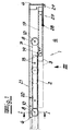
- a landing door with a door panel 1 consisting of two panels 2, 3, with the door closed access to a lift shaft 4 closes.
- the panels 2, 3 are on carriage 5 hung and led on the bottom and lead at a Opening and closing movement rectified movements different length. They move on parallel tracks with changing overlap to each other past.
- the closed door and with dashed Lines a door position during the opening and closing Closing movement shown. 1 takes one, that during a closing movement to the door frame 6
- Leading panel 3 connected to the ends of a pull rope 7 is that at the top of the other, lagging behind 2 panels rotatably mounted guide rollers 8 out and fixed in place.
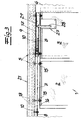
- a comparative consideration in particular of FIG. 2 and 3 takes you that the carriage 5 on rails 9th are guided, which slotted from the underside in the longitudinal direction Hollow profiles exist and in the interior of the Carriage 5 are movably inserted, and that the pulleys 8 with vertical axes of rotation 10 between the top the trailing panel 2 and the panel associated Running rail 9 are arranged.
- the hollow profiles 9 are extruded profiles pointing to the axis of symmetry 11 wedge-shaped running surfaces 12 on which the carriages 5 center. This prevents that the carriages 5 start at the lateral inner surfaces.
- the carriage 5 have rollers 13, the at a wheel carrier 14 are mounted. To the wheel carrier 14 connection means 15 are connected to the panel attachment, through the slot of the running rail. 9 extend (Fig. 4).
- Fig. 2 shows that the panels 2, 3 are suspended from panel supports 16, 17, which in turn are connected to the carriage 5.
- the pulleys 8 are on the panel carrier 16 of a closing movement trailing panel 2 stored.
- the panel carrier 16 is designed as an angle profile and has a horizontal Mounting leg 18 at the bottom of the running rail. 5 and a vertical leg 18.
- the pulleys 8 are stored on the mounting leg, on which also the Panel 2 is suspended.
- the vertical leg 18 extends down to the area of the running rail 9 and is supported on the running rail 9 from when on the panel. 2 an external lateral force acts.
- the panel carrier 17 of the leading panel 3 is U-shaped Carrier trained.
- the legs of the U-shaped Carriers are aligned horizontally.
- the upper leg is suspended on the carriage 5.
- On the lower leg the panel body 3 is attached.
- Guided pull cable 7 is at the U-shaped panel carrier end attached.
- the panel carrier 17 has a Tab 19 with an eyelet through which the pull cable 7 movable is guided.
- the pull rope 7 requires a stationary Fixation.
- the fixation takes place on a clamping device 20, which is arranged on the upper Zargenholm 21 of the door frame is.
- the suspension of the panels according to the invention is characterized by a low installation height. This allows the upper frame member 21 of the door frame at the from the hoistway 4th opposite visible side as a narrow aperture form.
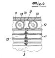
- the rails 9 consist of a channel profile, the a lower and upper tread 22, 23 and at one side is open. It is preferably as a sheet steel molding educated.
- the lower tread 22 is appropriate curved curved while the upper tread 23 even is trained.
- the carriage 5 consist of a as Angled profile trained panel carrier 24, on the respectively a panel 2, 3 is suspended and on which the at the lower tread 22 of the track 9 guided rollers 13 are stored. Additionally are on the panel carrier 24 supporting rollers 25 mounted on the upper tread 23 of the channel profile are performed. Support rollers 23 and rollers 22 are adjustable relative to each other. The form on the upper tread 23 guided support rollers 25 a lift-off protection.
- the trained as angle profiles panel carrier 24 have below the rails 9 a horizontal mounting leg for fastening the panel 2, 3.
- the panel carrier 24 of the lagging in a closing movement Panel 2 also has horizontal end portions on where the pulleys 8 are mounted.
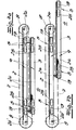
- FIGS. 7a and 7b show that the deflection rollers 8 for the pull rope have different diameters, so that the ends of the pull cable 7 offset parallel to the in Closing direction back end of the panel carrier 24 connected are. Further, the axes 26, 26 'of the different large pulleys 8 offset in parallel, wherein the parallel offset is chosen so that all sections of the guided around the pulleys 8 pull rope 7th extend parallel to the direction of the panels 2, 3.
- the door leaf 1 In the closed state, the door leaf 1 is locked to the door frame 6 and thereby secured against delay.
- the at a closing movement leading panel 3 is with a Lock 27 equipped, which the panel 3 in the closed state locked to the door frame 6.
- the Fig. 8 takes one, that the lock 27 one at the pit side Panel surface rotatably mounted actuating lever 28 and a cooperating with the actuating lever 28 latch lever 29 has.
- the latch lever 29 is above of the panel 3 in a space between the panel body and the running rail 9 is arranged and engages in the closed state in a recess 30 of the door frame.
- This arrangement has the advantage that the landing door and a in the exemplary embodiments not shown door of Carriage positioned at a small distance from each other can be.
Abstract
Description
Die Erfindung betrifft eine Fahrschachttür mit
Türzarge,
einem Türblatt aus mindestens zwei Paneelen, die an
Laufwagen aufgehängt sowie unterseitig geführt sind
und bei einer Öffnungs- und Schließbewegung gleichgerichtete
Bewegungen unterschiedlicher Länge ausführen
und sich dabei auf parallelen Bahnen mit ändernder
Überlappung aneinander vorbeibewegen, und
im oberen Zargenholm der Türzarge angeordneten Laufschienen
zur Führung der Laufwagen,
wobei das bei einer Schließbewegung bis zur Türzarge voreilende
Paneel an die Enden eines Zugseils angeschlossen
ist, welches über an der Oberseite des anderen, nacheilenden
Paneels drehbar gelagerte Umlenkrollen geführt und
ortsfest fixiert ist.The invention relates to a landing door with
door frame,
a door leaf of at least two panels, which are suspended from carriages and guided on the underside and execute in an opening and closing movement rectified movements of different lengths and thereby move on parallel paths with changing overlap each other, and
in the upper Zargenholm the door frame arranged rails for guiding the carriage,
wherein the leading in a closing movement to the door frame panel is connected to the ends of a pull rope, which is guided over at the top of the other, trailing panel rotatably mounted pulleys and fixed in place.
Fahrschachttüren des beschriebenen Aufbaus sind in der Praxis weit verbreitet. Bei allen bisher bekannten Ausführungen sind die Laufschienen als Flachstäbe ausgebildet und weisen die Laufwagen eine Laufradanordnung aus Laufrollen auf, die an der Oberkante und der Unterkante der Laufschienen geführt sind. Die Umlenkrollen für das die Bewegung des voreilenden Paneels steuernde Zugseil sind an vertikalen Trägern der Paneelaufhängung des nacheilenden Paneels angeordnet und um horizontale Achsen drehbar gelagert. Die bisher bekannten Aufhängungen bei Fahrschachttüren erfordern einen großen Einbauraum oberhalb der Paneele. Der obere Zargenholm der Türzarge muss daher an seiner vom Fahrschacht abgewandten, sichtbaren Seite als breite Blende ausgeführt werden. Dies stört den optischen Eindruck der Fahrschachttür und erfordert eine große Maueröffnung zum Einbau der Fahrschachttür.Fahrschachttüren the described structure are in the Practice widely used. In all previously known versions the rails are designed as flat bars and the carriages have an impeller assembly of rollers at the top and bottom of the Run rails are guided. The pulleys for the Movement of the leading panel controlling pull rope are on vertical beams of the panel suspension of the lagging Panels arranged and rotatable about horizontal axes stored. The previously known suspensions on landing doors require a large installation space above the Panels. The upper frame spar of the door frame must therefore its facing away from the shaft, visible side as wide aperture are executed. This disturbs the optical Impression of the landing door and requires a large wall opening for installation of the landing door.
Eine Fahrschachttür ist z.B. in JP-A-2 0000 26053 offenbart.A landing door is e.g. in JP-A-2 0000 26053.
Der Erfindung liegt die Aufgabe zugrunde, bei einer Fahrschachttür eine Türblattaufhängung anzugeben, die eine geringe Einbauhöhe erfordert und die Verwendung einer im Kopfbereich schmalen Türzarge ermöglicht.The invention is based on the object at a landing door specify a door leaf suspension, the one low installation height requires and the use of an im Head section allows narrow door frame.
Die Aufgabe wird bei einer Fahrschachttür des eingangs. beschriebenen Aufbaus erfindungsgemäß dadurch gelöst, dass die Laufschienen aus Hohlprofilen bestehen, in die Laufrollen der Laufwagen eingesetzt sind, und dass die Umlenkrollen mit vertikalen Drehachsen zwischen der Oberseite des nacheilenden Paneels und der dem Paneel zugeordneten Laufschiene angeordnet sind.The task is at a landing door of the entrance. described structure solved according to the invention that the rails consist of hollow sections, in the rollers the carriages are inserted, and that the pulleys with vertical axes of rotation between the top of the lagging panel and the panel associated with the track are arranged.
Im Rahmen der erfindungsgemäßen Lehre können die Laufschienen unterschiedlich gestaltet sein. Eine erste Ausführungsform sieht vor, dass die Hohlprofile unterseitig in Längsrichtung geschlitzt sind. Die Laufwagen sind in den Innenraum der Hohlprofile beweglich eingesetzt und weisen Laufradträger auf, an denen die Laufrollen gelagert sind. An die Laufradträger sind ferner Anschlussmittel zur Paneelbefestigung angeschlossen, die sich durch den Schlitz der Laufschiene erstrecken. Als Hohlprofile eignen sich besonders stranggeformte Profile, vorzugsweise aus Metall. In the context of the teaching of the invention, the rails be designed differently. A first embodiment provides that the hollow sections in the underside in Slotted longitudinal direction. The carriages are in the Interior of the hollow sections movably inserted and point Wheel carrier on which the rollers are mounted. To the wheel carrier are also connecting means for Panel mount connected through the slot extend the running rail. As hollow profiles are suitable especially extruded profiles, preferably of metal.
Die innenseitigen Laufflächen der Hohlprofile sind zweckmäßig zur Symmetrieachse keilförmig ausgerichtet. An den schräg ausgerichteten Laufflächen zentrieren sich die Laufwagen bei ihrer Bewegung, wodurch ein Anlaufen der Laufwagen an den seitlichen Wandflächen des Hohlprofils verhindert werden kann.The inside treads of the hollow sections are appropriate aligned wedge-shaped to the symmetry axis. To the sloping treads center the carriages during their movement, causing a tarnishing of the carriages prevented on the lateral wall surfaces of the hollow profile can be.
Im Rahmen der erfindungsgemäßen Lehre können die Laufschienen ferner aus einem Rinnenprofil bestehen, das eine untere und obere Lauffläche aufweist und an einer Seite offen ist. Die untere Lauffläche ist zweckmäßig ballig gekrümmt, während die obere Lauffläche eben ausgebildet ist. Durch die ballige Ausbildung der Lauffläche, welche Pendelbewegungen des Laufwagens zulässt, können Fluchtungsfehler zwischen der oberseitigen und unterseitigen Führung der Fahrschachttür korrigiert werden. Die obere Lauffläche, an der separate Stützrollen des Laufwagens geführt sind, dient lediglich als Abhebeschutz. Die beschriebene Ausführung hat Vorteile in Bezug auf Montage und Wartung, da die Laufrollen frei zugänglich sind und die Laufwagen seitlich in die Laufschienen eingesetzt und ggf. zu Wartungszwecken auch ausgebaut werden können. Das Rinnenprofil ist vorzugsweise als Stahlblechformteil ausgebildet.In the context of the teaching of the invention, the rails Furthermore, consist of a gutter profile, the one has lower and upper tread and on one side is open. The lower tread is suitably spherical curved, while the upper tread flat is. Due to the spherical shape of the tread, which Pendulum movements of the carriage allows misalignment between the top and bottom guides the landing door be corrected. The upper tread, are guided on the separate support rollers of the carriage, serves only as a withdrawal protection. The described embodiment has advantages in terms of installation and maintenance, as the Casters are freely accessible and the carriage side used in the rails and possibly for maintenance purposes can also be expanded. The gutter profile is preferably designed as a sheet steel molding.
Zur Verminderung der Laufgeräusche sind die Laufrollen zweckmäßig mit einer Hartgummibereifung versehen oder bestehen aus Hartgummi oder einem geeigneten Kunststoff.To reduce the running noise are the rollers expediently provided with a hard rubber tires or are made of hard rubber or a suitable plastic.
In weiterer Ausgestaltung lehrt die Erfindung, dass die Paneele an Paneelträgern aufgehängt sind, wobei an dem Paneelträger des bei einer Schließbewegung nacheilenden Paneels die Umlenkrollen gelagert sind und wobei das Zugseil an dem Paneelträger des voreilenden Paneels parallel geführt und endseitig befestigt ist. Zweckmäßig sind die Paneelträger als Winkelprofile ausgebildet, die unterhalb der Laufschienen einen horizontalen Montageschenkel zur Befestigung des Paneels und einen bis in den Bereich der Laufschienen vorstehenden vertikalen Schenkel aufweisen. Der sich bis in den Bereich der Laufschiene erstreckende vertikale Schenkel des Paneelträgers stützt sich an der Laufschiene ab, wenn auf das Paneel äußere Querkräfte wirken. Der in der beschriebenen Weise als Winkelprofil ausgebildete Laufradträger gibt dem Paneelkörper seitlichen Halt und verhindert Pendelbewegungen des Paneels, wenn von außen Querkräfte auf den Paneelkörper wirken. Der vertikale Schenkel kann oberseitig mit einer Abkantung versehen sein und/oder kann zusätzlich mit Gleitschuhen ausgerüstet sein, die bei einem Kontakt mit der Laufschiene die Reibung reduzieren. Sofern die Laufschienen als Rinnenprofil ausgebildet sind, sind die in den Laufschienen geführten Laufund Stützrollen an dem vertikalen Schenkel des Paneelträgers gelagert. Der als Winkelprofil ausgebildete Paneelträger und die an dem Paneelträger gelagerten Lauf- und Stützrollen bilden einen Laufwagen, an dem das Paneel unmittelbar aufgehängt ist.In a further embodiment, the invention teaches that the Panels are hung on panel carriers, wherein on the Panel carrier of the lagging in a closing movement Paneels the pulleys are mounted and wherein the pull rope parallel to the panel carrier of the leading panel guided and fixed at the end. Appropriately, the Panel carrier designed as angle profiles below the rails a horizontal mounting leg to Attach the panel and one into the area of the Running rails have protruding vertical leg. The extending into the region of the running rail vertical leg of the panel carrier is supported on the Running rail, if on the panel outer shear forces Act. The in the manner described as an angle profile Trained wheel carrier gives the panel body lateral Holds and prevents pendulum movements of the panel when off outside lateral forces act on the panel body. The vertical one Leg can be provided on the upper side with a fold and / or may additionally be equipped with sliding shoes, the friction in contact with the track rail to reduce. If the rails designed as gutter profile are, are run in the rails run and Support rollers on the vertical leg of the panel carrier stored. The designed as an angle profile panel carrier and the mounted on the panel carrier run and Support rollers form a carriage on which the panel is suspended directly.
Gemäß einer weiteren, bevorzugten Ausführung der Erfindung weisen die Umlenkrollen unterschiedliche Durchmesser auf, so dass die Enden des Zugseils parallel versetzt an das in Schließrichtung rückseitige Ende des Paneelträgers angeschlossen sind. Dabei sind die Achsen der unterschiedlich großen Umlenkrollen zweckmäßig parallel versetzt, wobei der Parallelversatz so gewählt ist, dass sich alle Abschnitte des um die Umlenkrollen geführten Zugseils parallel zu der Laufrichtung der Paneele erstrecken.According to a further preferred embodiment of the invention the pulleys have different diameters, so that the ends of the pull rope offset parallel to the in Closing direction connected back end of the panel carrier are. The axes are different expedient parallel offset large pulleys, wherein the Parallel offset is chosen so that all sections the guided around the pulleys pull rope parallel to the Extend running direction of the panels.
Bei geschlossenem Türblatt muss die Fahrschachttür gegen Aufschieben gesichert sein. Zu diesem Zweck ist an dem bei einer Schließbewegung voreilenden Paneel ein Schloss angeordnet, welches das Paneel im Schließzustand an der Türzarge verriegelt. Das Schloss weist einen an der fahrschachtseitigen Paneelfläche drehbar gelagerten Betätigungshebel und einen mit dem Betätigungshebel zusammenwirkenden Klinkenhebel auf. Der Klinkenhebel ist dabei oberhalb des Paneels in einem Raum zwischen dem Paneelkörper und der Laufschiene angeordnet und greift im Schließzustand in eine Ausnehmung der Türzarge ein. Bei der erfindungsgemäßen Ausbildung steht die Schließmechanik an der fahrschachtseitigen Paneelfläche nur wenig vor. Das hat den Vorteil, dass die Fahrschachttür und die Tür des Fahrkorbes in einem geringen Abstand positioniert werden können.When the door leaf is closed, the landing door must be closed Be deferred. For this purpose is at the at a closing movement leading panel arranged a lock which the panel in the closed state on the door frame locked. The lock has a at the pit side Panel surface rotatably mounted actuating lever and a cooperating with the operating lever Ratchet lever on. The latch lever is included above the panel in a space between the panel body and the running rail arranged and engages in Closed state in a recess of the door frame. In the According to the invention training is the locking mechanism the pit side panel only slightly before. That has the advantage of having the landing door and the door of the car be positioned at a small distance can.
Im Folgenden wird die Erfindung anhand einer lediglich ein Ausführungsbeispiel darstellenden Zeichnung erläutert. Es zeigen schematisch
- Fig. 1
- eine Fahrschachttür in der Draufsicht,
- Fig. 2
- die Ansicht I-I aus Fig. 1 in einer gegenüber Fig. 1 vergrößerten und detaillierteren Darstellung,
- Fig. 3
- eine Ansicht auf die Fahrschachttür aus der Blickrichtung III aus Fig. 1,
- Fig. 4
- ausschnittsweise den Schnitt IV-IV aus Fig. 2,
- Fig. 5
- eine weitere Ausführungsform der erfindungsgemäßen Fahrschachttür im Querschnitt,
- Fig. 6
- eine Seitenansicht der in Fig. 5 dargestellten Fahrschachttür aus der Blickrichtung V aus Fig. 4,
- Fig. 7a, 7b
- eine Draufsicht auf den Gegenstand der Fig. 5 und 6 in unterschiedlichen Öffnungsstellungen, und
- Fig. 8
- eine Schlossausbildung zur Verriegelung der Fahrschachttür im Schließzustand in der Draufsicht.
- Fig. 1
- a landing door in top view,
- Fig. 2
- 1 in a view enlarged and more detailed compared to FIG. 1,
- Fig. 3
- a view of the landing door from the viewpoint III of FIG. 1,
- Fig. 4
- 1 in section the section IV-IV of Fig. 2,
- Fig. 5
- a further embodiment of the landing door according to the invention in cross section,
- Fig. 6
- 5 is a side view of the landing door shown in FIG. 5 from the viewing direction V of FIG. 4,
- Fig. 7a, 7b
- a plan view of the subject matter of FIGS. 5 and 6 in different open positions, and
- Fig. 8
- a lock training for locking the landing door in the closed state in plan view.
In Fig. 1 ist in der Draufsicht eine Fahrschachttür mit
einem aus zwei Paneelen 2, 3 bestehenden Türblatt 1 dargestellt,
das bei geschlossener Tür den Zugang zu einem Fahrschacht
4 verschließt. Die Paneele 2, 3 sind an Laufwagen 5
aufgehängt sowie unterseitig geführt und führen bei einer
Öffnungs- und Schließbewegung gleichgerichtete Bewegungen
unterschiedlicher Länge aus. Sie bewegen sich dabei auf
parallelen Bahnen mit ändernder Überlappung aneinander
vorbei. In Fig. 1 ist die geschlossene Tür und mit gestrichelten
Linien eine Türstellung während der Öffnungsund
Schließbewegung dargestellt. Der Fig. 1 entnimmt man,
dass das bei einer Schließbewegung bis zur Türzarge 6
voreilende Paneel 3 an die Enden eines Zugseils 7 angeschlossen
ist, das über an der Oberseite des anderen, nacheilenden
Paneels 2 drehbar gelagerte Umlenkrollen 8 geführt
und ortsfest fixiert ist. Durch die Zugseilanordnung ist
der Fahrweg des voreilenden Paneels 3 stets doppelt so groß
wie der Fahrweg des nacheilenden Paneels.In Fig. 1, in the plan view, a landing door with
a
Einer vergleichenden Betrachtung insbesondere der Fig. 2
und 3 entnimmt man, dass die Laufwagen 5 an Laufschienen 9
geführt sind, die aus unterseitig in Längsrichtung geschlitzten
Hohlprofilen bestehen und in deren Innenraum die
Laufwagen 5 beweglich eingesetzt sind, und dass die Umlenkrollen
8 mit vertikalen Drehachsen 10 zwischen der Oberseite
des nacheilenden Paneels 2 und der dem Paneel zugeordneten
Laufschiene 9 angeordnet sind. Die Hohlprofile 9
sind stranggeformte Profile und weisen zur Symmetrieachse
11 keilförmig ausgerichtete Laufflächen 12 auf, an denen
sich die Laufwagen 5 zentrieren. Dadurch wird verhindert,
dass die Laufwagen 5 an den seitlichen Innenflächen anlaufen.
Die Laufwagen 5 weisen Laufrollen 13 auf, die an
einem Laufradträger 14 gelagert sind. An die Laufradträger
14 sind Anschlussmittel 15 zur Paneelbefestigung angeschlossen,
die sich durch den Schlitz der Laufschiene 9
erstrecken (Fig. 4).A comparative consideration in particular of FIG. 2
and 3 takes you that the
Insbesondere aus der Fig. 2 geht hervor, dass die Paneele
2, 3 an Paneelträgern 16, 17 aufgehängt sind, die ihrerseits
mit den Laufwagen 5 verbunden sind. Die Umlenkrollen
8 sind an dem Paneelträger 16 des bei einer Schließbewegung
nacheilenden Paneels 2 gelagert. Der Paneelträger 16 ist
als Winkelprofil ausgebildet und weist einen horizontalen
Montageschenkel 18 an der Unterseite der Laufschiene 5
sowie einen vertikalen Schenkel 18 auf. Die Umlenkrollen 8
sind an dem Montageschenkel gelagert, an dem auch das
Paneel 2 aufgehängt ist. Der vertikale Schenkel 18 erstreckt
sich bis in den Bereich der Laufschiene 9 und
stützt sich an der Laufschiene 9 ab, wenn auf das Paneel 2
eine äußere Querkraft wirkt.In particular, from Fig. 2 shows that the
Der Paneelträger 17 des voreilenden Paneels 3 ist als U-förmiger
Träger ausgebildet. Die Schenkel des U-förmigen
Trägers sind horizontal ausgerichtet. Der obere Schenkel
ist an dem Laufwagen 5 aufgehängt. An dem unteren Schenkel
ist der Paneelkörper 3 angehängt. Das um die Umlenkrollen 8
geführte Zugseil 7 ist an dem U-förmigen Paneelträger endseitig
befestigt. Ferner weist der Paneelträger 17 eine
Lasche 19 mit einer Öse auf, durch die das Zugseil 7 beweglich
geführt ist. Das Zugseil 7 bedarf einer ortsfesten
Fixierung. Die Fixierung erfolgt an einer Klemmeinrichtung
20, die an dem oberen Zargenholm 21 der Türzarge angeordnet
ist.The
Die erfindungsgemäße Aufhängung der Paneele zeichnet sich
durch eine geringe Einbauhöhe aus. Das ermöglicht es, den
oberen Zargenholm 21 der Türzarge an der vom Fahrschacht 4
abgewandten sichtbaren Seite als schmale Blende auszubilden.
Bei einer in den Fig. 5 und 6 dargestellten Ausführung
bestehen die Laufschienen 9 aus einem Rinnenprofil, das
eine untere und obere Lauffläche 22, 23 aufweist und an
einer Seite offen ist. Es ist vorzugsweise als Stahlblechformteil
ausgebildet. Die untere Lauffläche 22 ist zweckmäßig
ballig gekrümmt, während die obere Lauffläche 23 eben
ausgebildet ist. Die Laufwagen 5 bestehen aus einem als
Winkelprofil ausgebildeten Paneelträger 24, an dem jeweils
ein Paneel 2, 3 aufgehängt ist und an dem die an der
unteren Lauffläche 22 der Laufschiene 9 geführten Laufrollen
13 gelagert sind. Zusätzlich sind an dem Paneelträger
24 Stützrollen 25 gelagert, die an der oberen Lauffläche
23 des Rinnenprofils geführt sind. Stützrollen 23
und Laufrollen 22 sind relativ zueinander verstellbar. Die
an der oberen Lauffläche 23 geführten Stützrollen 25 bilden
einen Abhebeschutz.The suspension of the panels according to the invention is characterized
by a low installation height. This allows the
Die als Winkelprofile ausgebildeten Paneelträger 24 weisen
unterhalb der Laufschienen 9 einen horizontalen Montageschenkel
zur Befestigung des Paneels 2, 3 auf. Der Paneelträger
24 des bei einer Schließbewegung nacheilenden
Paneels 2 weist ferner horizontale Endabschnitte auf, an
denen die Umlenkrollen 8 gelagert sind.The trained as angle
Den Fig. 7a und 7b entnimmt man, dass die Umlenkrollen 8
für das Zugseil unterschiedliche Durchmesser aufweisen, so
dass die Enden des Zugseils 7 parallel versetzt an das in
Schließrichtung rückseitige Ende des Paneelträgers 24 angeschlossen
sind. Ferner sind die Achsen 26, 26' der unterschiedlich
großen Umlenkrollen 8 parallel versetzt, wobei
der Parallelversatz so gewählt ist, dass sich alle Abschnitte
des um die Umlenkrollen 8 geführten Zugseils 7
parallel zu der Laufrichtung der Paneele 2, 3 erstrecken.FIGS. 7a and 7b show that the
Im Schließzustand ist das Türblatt 1 an der Türzarge 6 verriegelt
und dadurch gegen Aufschieben gesichert. Das bei
einer Schließbewegung voreilende Paneel 3 ist mit einem
Schloss 27 ausgerüstet, welches das Paneel 3 im Schließzustand
an der Türzarge 6 verriegelt. Der Fig. 8 entnimmt
man, dass das Schloss 27 einen an der fahrschachtseitigen
Paneelfläche drehbar gelagerten Betätigungshebel 28 und
einen mit dem Betätigungshebel 28 zusammenwirkenden Klinkenhebel
29 aufweist. Dabei ist der Klinkenhebel 29 oberhalb
des Paneels 3 in einem Raum zwischen dem Paneelkörper
und der Laufschiene 9 angeordnet und greift im Schließzustand
in eine Ausnehmung 30 der Türzarge ein. Diese Anordnung
hat den Vorteil, dass die Fahrschachttür und eine
in den Ausführungsbeispielen nicht dargestellte Tür des
Fahrkorbes mit geringem Abstand zueinander positioniert
werden können.In the closed state, the
Claims (13)
- A lift shaft door, comprising
a door frame (6),
a door leaf (1) comprising at least two panels (2, 3) which are suspended on running carriages (5) and which are guided on their undersides, and which during an opening and closing movement execute movements of different lengths in the same direction and at the same time move past each other with a varying overlap on parallel tracks, and
comprising running rails (9) disposed in the top frame bar (21) of the door frame, for guiding the running carriages (5),
wherein the leading panel (3) during a closing movement as far as the door frame (6) is attached to the ends of a traction cable (7) which is fixedly fastened and is passed over deflection rollers (8) which are rotatably mounted on the top of the other, trailing panel (2), wherein the running rails (9) consist of hollow sections in which running rollers (13) of the running carriages (5) are inserted, characterised in that the deflection rollers (8) are disposed, with vertical axes of rotation (10), between the top of the trailing panel (2) and the running rail (9) which is associated with said panel (2). - A lift shaft door according to claim 1, characterised in that the undersides of the hollow sections are longitudinally slotted, that the running carriages (5) which are movably inserted in the interior space of the hollow sections comprise running wheel supports (14) on which the running rollers (13) are mounted, and that attachment means (15) for fixing the panels are attached to the running wheel supports (14) and extend through the slot in the running rail (9).
- A lift shaft door according to claim 2, characterised in that the hollow sections comprise running faces (12) which are aligned in the shape of a wedge in relation to the axis of symmetry and on which the running carriages (5) are centred.
- A lift shaft door according to any one of claims 1 to 3, characterised in that extruded sections are provided as the hollow sections.
- A lift shaft door according to claim 1, characterised in that the hollow sections are formed as a channel section which has a lower and an upper running face (22, 23) and which is open on one side.
- A lift shaft door according to claim 5, characterised in that the lower running face (22) exhibits convex curvature and the upper running face (23) is of flat construction.
- A lift shaft door according to claim 5 or 6, characterised in that the channel section consists of a shaped sheet steel part.
- A lift shaft door according to any one of claims 1 to 7, characterised in that the panels (2, 3) are suspended on panel supports (16, 17, 24), wherein the deflection rollers (8) are mounted on the panel support of the panel (2) which is the trailing panel during a closing movement, and wherein the traction cable (7) is guided parallel to the panel support of the leading panel (3) and is fixed at its end thereto.
- A lift shaft door according to claim 8, characterised in that the panel supports (24) are formed as angle sections which comprise a horizontal mounting limb underneath the running rails (9) for fixing the panel (2, 3) and optionally for mounting the deflection rollers (8), and which comprise a vertical limb (18) which protrudes into the region of the running rails.
- A lift shaft door according to claim 9, characterised in that the running rollers (13) which are guided in the running rails (9) are mounted on the vertical limb (18) of the angle section.
- A lift shaft door according to any one of claims 8 to 10, characterised in that the deflection rollers (8) are of different diameters so that the ends of the traction cable (7) are attached, offset in parallel, to the rear end of the panel support (24) in the direction of closure.
- A lift shaft door according to claim 11, characterised in that the axes (26, 26') of the deflection rollers (8) of different sizes are offset in parallel, wherein the parallel offset is selected so that all sections of the traction cable (7) which is guided round the deflection rollers (8) extend parallel to the running direction of the panels (2, 3).
- A lift shaft door according to any one of claims 1 to 12, characterised in that a lock (27), which in the closed state locks the panel (3) to the door frame (6), is disposed on the leading panel (3) during a closing movement, wherein the lock (27) comprises an operating lever (28) which is rotatably mounted on the panel face on the lift shaft side, and the lock comprises a latching lever (29) which cooperates with the operating lever (28), wherein the latching lever (29) is disposed above the panel (3) in a space between the panel body and the running rail (9) and in the closed state fits into an aperture
Priority Applications (1)
| Application Number | Priority Date | Filing Date | Title |
|---|---|---|---|
| SI200230007T SI1281655T1 (en) | 2001-07-31 | 2002-07-08 | Landing door |
Applications Claiming Priority (2)
| Application Number | Priority Date | Filing Date | Title |
|---|---|---|---|
| DE10137257A DE10137257C2 (en) | 2001-07-31 | 2001-07-31 | Lift door |
| DE10137257 | 2001-07-31 |
Publications (2)
| Publication Number | Publication Date |
|---|---|
| EP1281655A1 EP1281655A1 (en) | 2003-02-05 |
| EP1281655B1 true EP1281655B1 (en) | 2003-10-29 |
Family
ID=7693702
Family Applications (1)
| Application Number | Title | Priority Date | Filing Date |
|---|---|---|---|
| EP02015176A Expired - Lifetime EP1281655B1 (en) | 2001-07-31 | 2002-07-08 | Landing door |
Country Status (8)
| Country | Link |
|---|---|
| EP (1) | EP1281655B1 (en) |
| AT (1) | ATE253011T1 (en) |
| DE (2) | DE10137257C2 (en) |
| DK (1) | DK1281655T3 (en) |
| ES (1) | ES2210210T3 (en) |
| PT (1) | PT1281655E (en) |
| SI (1) | SI1281655T1 (en) |
| TR (1) | TR200400067T4 (en) |
Families Citing this family (2)
| Publication number | Priority date | Publication date | Assignee | Title |
|---|---|---|---|---|
| DE10230799B4 (en) * | 2002-07-08 | 2006-10-26 | Novoferm Gmbh | Lift door |
| DE102014201687C5 (en) * | 2014-01-30 | 2019-03-28 | Gebr. Willach Gmbh | Telescopic sliding door system |
Family Cites Families (4)
| Publication number | Priority date | Publication date | Assignee | Title |
|---|---|---|---|---|
| US1148652A (en) * | 1915-02-10 | 1915-08-03 | Herman Beltz | Elevator-door hanger. |
| IT958881B (en) * | 1972-05-16 | 1973-10-30 | Tesio Di Pietro Tesio | IMPROVEMENTS TO SLIDING DOORS FLIGHTS PARTICULARLY AUTOMATIC DOORS OF ELEVATORS GOODS LIFTS AND SIMILAR |
| ATE202763T1 (en) * | 1994-05-11 | 2001-07-15 | Inventio Ag | ROLLERS OF A ROLLER GUIDE FOR SLIDING ELEVATOR DOORS |
| JP2000026053A (en) * | 1998-07-09 | 2000-01-25 | Otis Elevator Co | Door opening/closing device for elevator |
-
2001
- 2001-07-31 DE DE10137257A patent/DE10137257C2/en not_active Expired - Fee Related
-
2002
- 2002-07-08 AT AT02015176T patent/ATE253011T1/en not_active IP Right Cessation
- 2002-07-08 ES ES02015176T patent/ES2210210T3/en not_active Expired - Lifetime
- 2002-07-08 SI SI200230007T patent/SI1281655T1/en unknown
- 2002-07-08 DE DE50200086T patent/DE50200086D1/en not_active Expired - Fee Related
- 2002-07-08 PT PT02015176T patent/PT1281655E/en unknown
- 2002-07-08 EP EP02015176A patent/EP1281655B1/en not_active Expired - Lifetime
- 2002-07-08 DK DK02015176T patent/DK1281655T3/en active
- 2002-07-08 TR TR2004/00067T patent/TR200400067T4/en unknown
Also Published As
| Publication number | Publication date |
|---|---|
| TR200400067T4 (en) | 2004-02-23 |
| PT1281655E (en) | 2004-03-31 |
| DK1281655T3 (en) | 2004-03-08 |
| ES2210210T3 (en) | 2004-07-01 |
| EP1281655A1 (en) | 2003-02-05 |
| DE50200086D1 (en) | 2003-12-04 |
| DE10137257A1 (en) | 2003-02-27 |
| DE10137257C2 (en) | 2003-05-28 |
| SI1281655T1 (en) | 2004-04-30 |
| ATE253011T1 (en) | 2003-11-15 |
Similar Documents
| Publication | Publication Date | Title |
|---|---|---|
| EP0327727B1 (en) | Guiding device for a vertically slidable window | |
| EP1092074B1 (en) | Articulated overhead gate for particularly small drop heights | |
| EP1176280B1 (en) | Door, especially a garage door | |
| EP0936119B1 (en) | Pivotable sliding door for vehicles | |
| EP3901402B1 (en) | Carriage for a sliding door | |
| EP1281655B1 (en) | Landing door | |
| DE10354255A1 (en) | Window regulator cable assembly | |
| DE10230799B4 (en) | Lift door | |
| DE102006016961B4 (en) | sectional | |
| EP0679788A1 (en) | Trolley as well as rail and sliding assembly | |
| AT410819B (en) | DOOR MOUNTING | |
| DE2931111A1 (en) | Commercial vehicle side wall - has lower panels hinging down to retract upper panels along rails over rollers supporting them when closed | |
| EP1034999B1 (en) | Freight waggon with a sliding side | |
| DE19731932C2 (en) | Sectional gate for particularly low lintel heights | |
| EP1437469B1 (en) | Window | |
| EP1039083A2 (en) | Sectional door | |
| EP2677100A2 (en) | Sliding door assembly | |
| DE19715712A1 (en) | Motor driven door mechanism for curved path sectional door in garage | |
| DE10100894B4 (en) | Sectional gate for a room with a low ceiling height | |
| EP1371598A1 (en) | Landing door | |
| EP1496185A1 (en) | Sectional door | |
| DE10205448C1 (en) | Door operating drive for sectional door has carriage displaced along ceiling-mounted drive rail coupled to uppermost door panel section via push rod | |
| DE10318251B4 (en) | Door drive, in particular for swinging or sectional doors | |
| DE10235671A1 (en) | Door rail and door roller drive mechanism for large aircraft hanger doors is located within sub-surface void | |
| EP0075268A1 (en) | Guiding rail section with a trolley for a door actuator |
Legal Events
| Date | Code | Title | Description |
|---|---|---|---|
| PUAI | Public reference made under article 153(3) epc to a published international application that has entered the european phase |
Free format text: ORIGINAL CODE: 0009012 |
|
| AK | Designated contracting states |
Designated state(s): AT BE BG CH CY CZ DE DK EE ES FI FR GB GR IE IT LI LU MC NL PT SE SK TR |
|
| AX | Request for extension of the european patent |
Extension state: AL LT LV MK RO SI |
|
| 17P | Request for examination filed |
Effective date: 20021221 |
|
| GRAH | Despatch of communication of intention to grant a patent |
Free format text: ORIGINAL CODE: EPIDOS IGRA |
|
| GRAH | Despatch of communication of intention to grant a patent |
Free format text: ORIGINAL CODE: EPIDOS IGRA |
|
| GRAA | (expected) grant |
Free format text: ORIGINAL CODE: 0009210 |
|
| AKX | Designation fees paid |
Designated state(s): AT BE BG CH CY CZ DE DK EE ES FI FR GB GR IE IT LI LU MC NL PT SE SK TR |
|
| AXX | Extension fees paid |
Extension state: SI Payment date: 20021221 Extension state: LT Payment date: 20021221 Extension state: LV Payment date: 20021221 Extension state: RO Payment date: 20021221 |
|
| AK | Designated contracting states |
Kind code of ref document: B1 Designated state(s): AT BE BG CH CY CZ DE DK EE ES FI FR GB GR IE IT LI LU MC NL PT SE SK TR |
|
| AX | Request for extension of the european patent |
Extension state: LT LV RO SI |
|
| PG25 | Lapsed in a contracting state [announced via postgrant information from national office to epo] |
Ref country code: CY Free format text: LAPSE BECAUSE OF FAILURE TO SUBMIT A TRANSLATION OF THE DESCRIPTION OR TO PAY THE FEE WITHIN THE PRESCRIBED TIME-LIMIT Effective date: 20031029 |
|
| REG | Reference to a national code |
Ref country code: GB Ref legal event code: FG4D Free format text: NOT ENGLISH |
|
| REG | Reference to a national code |
Ref country code: CH Ref legal event code: EP |
|
| REG | Reference to a national code |
Ref country code: IE Ref legal event code: FG4D Free format text: GERMAN |
|
| REF | Corresponds to: |
Ref document number: 50200086 Country of ref document: DE Date of ref document: 20031204 Kind code of ref document: P |
|
| REG | Reference to a national code |
Ref country code: CH Ref legal event code: NV Representative=s name: KELLER & PARTNER PATENTANWAELTE AG |
|
| GBT | Gb: translation of ep patent filed (gb section 77(6)(a)/1977) |
Effective date: 20040121 |
|
| REG | Reference to a national code |
Ref country code: SE Ref legal event code: TRGR |
|
| REG | Reference to a national code |
Ref country code: GR Ref legal event code: EP Ref document number: 20040400230 Country of ref document: GR |
|
| REG | Reference to a national code |
Ref country code: DK Ref legal event code: T3 |
|
| REG | Reference to a national code |
Ref country code: PT Ref legal event code: SC4A Free format text: AVAILABILITY OF NATIONAL TRANSLATION Effective date: 20040114 |
|
| REG | Reference to a national code |
Ref country code: EE Ref legal event code: FG4A Ref document number: E000004 Country of ref document: EE Effective date: 20040127 |
|
| REG | Reference to a national code |
Ref country code: ES Ref legal event code: FG2A Ref document number: 2210210 Country of ref document: ES Kind code of ref document: T3 |
|
| PGFP | Annual fee paid to national office [announced via postgrant information from national office to epo] |
Ref country code: TR Payment date: 20040705 Year of fee payment: 3 |
|
| PG25 | Lapsed in a contracting state [announced via postgrant information from national office to epo] |
Ref country code: LU Free format text: LAPSE BECAUSE OF NON-PAYMENT OF DUE FEES Effective date: 20040708 |
|
| PGFP | Annual fee paid to national office [announced via postgrant information from national office to epo] |
Ref country code: EE Payment date: 20040708 Year of fee payment: 3 Ref country code: PT Payment date: 20040708 Year of fee payment: 3 |
|
| PGFP | Annual fee paid to national office [announced via postgrant information from national office to epo] |
Ref country code: DK Payment date: 20040726 Year of fee payment: 3 Ref country code: FI Payment date: 20040726 Year of fee payment: 3 |
|
| PGFP | Annual fee paid to national office [announced via postgrant information from national office to epo] |
Ref country code: GR Payment date: 20040727 Year of fee payment: 3 |
|
| PGFP | Annual fee paid to national office [announced via postgrant information from national office to epo] |
Ref country code: IE Payment date: 20040728 Year of fee payment: 3 |
|
| ET | Fr: translation filed | ||
| PG25 | Lapsed in a contracting state [announced via postgrant information from national office to epo] |
Ref country code: MC Free format text: LAPSE BECAUSE OF NON-PAYMENT OF DUE FEES Effective date: 20040731 |
|
| PGFP | Annual fee paid to national office [announced via postgrant information from national office to epo] |
Ref country code: BG Payment date: 20040831 Year of fee payment: 3 |
|
| PLBE | No opposition filed within time limit |
Free format text: ORIGINAL CODE: 0009261 |
|
| STAA | Information on the status of an ep patent application or granted ep patent |
Free format text: STATUS: NO OPPOSITION FILED WITHIN TIME LIMIT |
|
| 26N | No opposition filed |
Effective date: 20040730 |
|
| REG | Reference to a national code |
Ref country code: SI Ref legal event code: IF |
|
| PG25 | Lapsed in a contracting state [announced via postgrant information from national office to epo] |
Ref country code: IE Free format text: LAPSE BECAUSE OF NON-PAYMENT OF DUE FEES Effective date: 20050708 |
|
| PG25 | Lapsed in a contracting state [announced via postgrant information from national office to epo] |
Ref country code: FI Free format text: LAPSE BECAUSE OF NON-PAYMENT OF DUE FEES Effective date: 20050710 |
|
| PG25 | Lapsed in a contracting state [announced via postgrant information from national office to epo] |
Ref country code: EE Free format text: LAPSE BECAUSE OF NON-PAYMENT OF DUE FEES Effective date: 20050731 |
|
| PG25 | Lapsed in a contracting state [announced via postgrant information from national office to epo] |
Ref country code: DK Free format text: LAPSE BECAUSE OF NON-PAYMENT OF DUE FEES Effective date: 20050801 |
|
| PG25 | Lapsed in a contracting state [announced via postgrant information from national office to epo] |
Ref country code: PT Free format text: LAPSE BECAUSE OF NON-PAYMENT OF DUE FEES Effective date: 20060109 |
|
| PG25 | Lapsed in a contracting state [announced via postgrant information from national office to epo] |
Ref country code: BG Free format text: LAPSE BECAUSE OF NON-PAYMENT OF DUE FEES Effective date: 20060131 |
|
| LTLA | Lt: lapse of european patent or patent extension |
Effective date: 20050708 |
|
| REG | Reference to a national code |
Ref country code: EE Ref legal event code: MM4A Ref document number: E000004 Country of ref document: EE Effective date: 20050731 |
|
| REG | Reference to a national code |
Ref country code: DK Ref legal event code: EBP |
|
| REG | Reference to a national code |
Ref country code: IE Ref legal event code: MM4A |
|
| PGFP | Annual fee paid to national office [announced via postgrant information from national office to epo] |
Ref country code: DE Payment date: 20070619 Year of fee payment: 6 |
|
| PGFP | Annual fee paid to national office [announced via postgrant information from national office to epo] |
Ref country code: ES Payment date: 20070727 Year of fee payment: 6 |
|
| PGFP | Annual fee paid to national office [announced via postgrant information from national office to epo] |
Ref country code: AT Payment date: 20070716 Year of fee payment: 6 Ref country code: CH Payment date: 20070713 Year of fee payment: 6 Ref country code: SK Payment date: 20070706 Year of fee payment: 6 |
|
| PGFP | Annual fee paid to national office [announced via postgrant information from national office to epo] |
Ref country code: CZ Payment date: 20070704 Year of fee payment: 6 Ref country code: GB Payment date: 20070720 Year of fee payment: 6 |
|
| PGFP | Annual fee paid to national office [announced via postgrant information from national office to epo] |
Ref country code: BE Payment date: 20070802 Year of fee payment: 6 Ref country code: IT Payment date: 20070721 Year of fee payment: 6 Ref country code: NL Payment date: 20070716 Year of fee payment: 6 Ref country code: SE Payment date: 20070712 Year of fee payment: 6 |
|
| PG25 | Lapsed in a contracting state [announced via postgrant information from national office to epo] |
Ref country code: GR Free format text: LAPSE BECAUSE OF NON-PAYMENT OF DUE FEES Effective date: 20031029 |
|
| PGFP | Annual fee paid to national office [announced via postgrant information from national office to epo] |
Ref country code: FR Payment date: 20070710 Year of fee payment: 6 |
|
| REG | Reference to a national code |
Ref country code: CH Ref legal event code: PL |
|
| EUG | Se: european patent has lapsed | ||
| GBPC | Gb: european patent ceased through non-payment of renewal fee |
Effective date: 20080708 |
|
| NLV4 | Nl: lapsed or anulled due to non-payment of the annual fee |
Effective date: 20090201 |
|
| PG25 | Lapsed in a contracting state [announced via postgrant information from national office to epo] |
Ref country code: DE Free format text: LAPSE BECAUSE OF NON-PAYMENT OF DUE FEES Effective date: 20090203 Ref country code: AT Free format text: LAPSE BECAUSE OF NON-PAYMENT OF DUE FEES Effective date: 20080708 |
|
| REG | Reference to a national code |
Ref country code: FR Ref legal event code: ST Effective date: 20090331 |
|
| PG25 | Lapsed in a contracting state [announced via postgrant information from national office to epo] |
Ref country code: SK Free format text: LAPSE BECAUSE OF NON-PAYMENT OF DUE FEES Effective date: 20080708 Ref country code: CZ Free format text: LAPSE BECAUSE OF NON-PAYMENT OF DUE FEES Effective date: 20080708 Ref country code: NL Free format text: LAPSE BECAUSE OF NON-PAYMENT OF DUE FEES Effective date: 20090201 |
|
| PG25 | Lapsed in a contracting state [announced via postgrant information from national office to epo] |
Ref country code: LI Free format text: LAPSE BECAUSE OF NON-PAYMENT OF DUE FEES Effective date: 20080731 Ref country code: CH Free format text: LAPSE BECAUSE OF NON-PAYMENT OF DUE FEES Effective date: 20080731 Ref country code: GB Free format text: LAPSE BECAUSE OF NON-PAYMENT OF DUE FEES Effective date: 20080708 |
|
| REG | Reference to a national code |
Ref country code: SI Ref legal event code: KO00 Effective date: 20090326 |
|
| PG25 | Lapsed in a contracting state [announced via postgrant information from national office to epo] |
Ref country code: IT Free format text: LAPSE BECAUSE OF NON-PAYMENT OF DUE FEES Effective date: 20080708 Ref country code: FR Free format text: LAPSE BECAUSE OF NON-PAYMENT OF DUE FEES Effective date: 20080731 |
|
| REG | Reference to a national code |
Ref country code: ES Ref legal event code: FD2A Effective date: 20080709 |
|
| PG25 | Lapsed in a contracting state [announced via postgrant information from national office to epo] |
Ref country code: TR Free format text: LAPSE BECAUSE OF FAILURE TO SUBMIT A TRANSLATION OF THE DESCRIPTION OR TO PAY THE FEE WITHIN THE PRESCRIBED TIME-LIMIT Effective date: 20031029 |
|
| PG25 | Lapsed in a contracting state [announced via postgrant information from national office to epo] |
Ref country code: ES Free format text: LAPSE BECAUSE OF NON-PAYMENT OF DUE FEES Effective date: 20080709 |
|
| PG25 | Lapsed in a contracting state [announced via postgrant information from national office to epo] |
Ref country code: BE Free format text: LAPSE BECAUSE OF NON-PAYMENT OF DUE FEES Effective date: 20080731 Ref country code: SE Free format text: LAPSE BECAUSE OF NON-PAYMENT OF DUE FEES Effective date: 20080709 |