EP1281601A2 - Die unsachgemässe Regelung eines geregelten Systems verhindernder Drehwinkelsensor - Google Patents
Die unsachgemässe Regelung eines geregelten Systems verhindernder Drehwinkelsensor Download PDFInfo
- Publication number
- EP1281601A2 EP1281601A2 EP02016792A EP02016792A EP1281601A2 EP 1281601 A2 EP1281601 A2 EP 1281601A2 EP 02016792 A EP02016792 A EP 02016792A EP 02016792 A EP02016792 A EP 02016792A EP 1281601 A2 EP1281601 A2 EP 1281601A2
- Authority
- EP
- European Patent Office
- Prior art keywords
- angle
- detection signal
- signal
- control section
- rotational
- Prior art date
- Legal status (The legal status is an assumption and is not a legal conclusion. Google has not performed a legal analysis and makes no representation as to the accuracy of the status listed.)
- Granted
Links
- 238000001514 detection method Methods 0.000 claims abstract description 191
- 230000005856 abnormality Effects 0.000 claims abstract description 59
- 238000004364 calculation method Methods 0.000 claims description 26
- 238000000034 method Methods 0.000 description 9
- 230000002159 abnormal effect Effects 0.000 description 7
- 238000010586 diagram Methods 0.000 description 7
- 230000007935 neutral effect Effects 0.000 description 7
- 230000004907 flux Effects 0.000 description 6
- 239000000725 suspension Substances 0.000 description 6
- 230000004044 response Effects 0.000 description 3
- NCGICGYLBXGBGN-UHFFFAOYSA-N 3-morpholin-4-yl-1-oxa-3-azonia-2-azanidacyclopent-3-en-5-imine;hydrochloride Chemical compound Cl.[N-]1OC(=N)C=[N+]1N1CCOCC1 NCGICGYLBXGBGN-UHFFFAOYSA-N 0.000 description 2
- 230000003247 decreasing effect Effects 0.000 description 2
- 230000005540 biological transmission Effects 0.000 description 1
- 230000000295 complement effect Effects 0.000 description 1
- 238000007796 conventional method Methods 0.000 description 1
Images




Classifications
-
- G—PHYSICS
- G01—MEASURING; TESTING
- G01D—MEASURING NOT SPECIALLY ADAPTED FOR A SPECIFIC VARIABLE; ARRANGEMENTS FOR MEASURING TWO OR MORE VARIABLES NOT COVERED IN A SINGLE OTHER SUBCLASS; TARIFF METERING APPARATUS; MEASURING OR TESTING NOT OTHERWISE PROVIDED FOR
- G01D5/00—Mechanical means for transferring the output of a sensing member; Means for converting the output of a sensing member to another variable where the form or nature of the sensing member does not constrain the means for converting; Transducers not specially adapted for a specific variable
- G01D5/12—Mechanical means for transferring the output of a sensing member; Means for converting the output of a sensing member to another variable where the form or nature of the sensing member does not constrain the means for converting; Transducers not specially adapted for a specific variable using electric or magnetic means
- G01D5/244—Mechanical means for transferring the output of a sensing member; Means for converting the output of a sensing member to another variable where the form or nature of the sensing member does not constrain the means for converting; Transducers not specially adapted for a specific variable using electric or magnetic means influencing characteristics of pulses or pulse trains; generating pulses or pulse trains
- G01D5/24457—Failure detection
- G01D5/24461—Failure detection by redundancy or plausibility
-
- B—PERFORMING OPERATIONS; TRANSPORTING
- B62—LAND VEHICLES FOR TRAVELLING OTHERWISE THAN ON RAILS
- B62D—MOTOR VEHICLES; TRAILERS
- B62D15/00—Steering not otherwise provided for
- B62D15/02—Steering position indicators ; Steering position determination; Steering aids
-
- G—PHYSICS
- G01—MEASURING; TESTING
- G01D—MEASURING NOT SPECIALLY ADAPTED FOR A SPECIFIC VARIABLE; ARRANGEMENTS FOR MEASURING TWO OR MORE VARIABLES NOT COVERED IN A SINGLE OTHER SUBCLASS; TARIFF METERING APPARATUS; MEASURING OR TESTING NOT OTHERWISE PROVIDED FOR
- G01D5/00—Mechanical means for transferring the output of a sensing member; Means for converting the output of a sensing member to another variable where the form or nature of the sensing member does not constrain the means for converting; Transducers not specially adapted for a specific variable
- G01D5/12—Mechanical means for transferring the output of a sensing member; Means for converting the output of a sensing member to another variable where the form or nature of the sensing member does not constrain the means for converting; Transducers not specially adapted for a specific variable using electric or magnetic means
- G01D5/244—Mechanical means for transferring the output of a sensing member; Means for converting the output of a sensing member to another variable where the form or nature of the sensing member does not constrain the means for converting; Transducers not specially adapted for a specific variable using electric or magnetic means influencing characteristics of pulses or pulse trains; generating pulses or pulse trains
- G01D5/24409—Interpolation using memories
Definitions
- the present invention relates to a rotational angle detector, and particularly to a rotational angle detector which prevents a controlled system from being improperly controlled by promptly identifying an abnormality of a detected angle detection signal or by promptly outputting an angle set signal with an abnormality signal added, when the rotational state of a rotor such as the steering shaft of a vehicle is detected as an angle detection signal, an angle set signal is generated based on the result of the detection and the controlled system is controlled using the angle set signal.
- a rotational angle detector is designed to detect the rotational angle of a rotor to control a controlled system according to the result of the detection. It comprises at least the following: a rotational angle detecting section which detects the rotational state of the rotor, generates an angle detection signal and sends the angle detection signal to a control section; a control section which generates an angle set signal by performing calculation on the - received angle detection signal in a prescribed manner and sends the angle set signal to a bus line; and a controller which receives the angle set signal sent through the bus line and controls the controlled system in response to the received angle set signal.
- this rotational angle detector When this rotational angle detector is to be used to detect the rotational angle of the steering shaft of a vehicle, the detector is mounted in the vehicle with its rotational angle detection section connected to the steering shaft of the vehicle.
- FIG. 10A and FIG. 10B are sectional views showing an example of the structure of one of the above-said rotary sensors; FIG. 10A is a transverse sectional view and FIG. 10B is a sectional view taken along the line 10B-10B of FIG. 10A.
- this rotary sensor comprises: a case 71, a rotor 72, a rotary shaft 73, a bearing 74, a worm gear 75, a slider 76, a first magnet 77 1 , a second magnet 77 2 , a first Hall element 78 1 , a second Hall element 78 2 , a third Hall element 78 3 , and a circuit board 79.
- the rotor 72 is connected with the steering shaft of the vehicle at its center and there are many gear teeth on its circumference.
- the rotary shaft 73, around which the worm gear 75 is fitted, rotates in conjunction with the worm gear 75.
- the screw grooves in the outer surface of the rotary shaft 73 engage with the screw grooves in the inner surface of the slider 76 so that the slider 76 slides in the axial direction of the rotary shaft 73 as the rotary shaft 73 turns.
- the rotary shaft 73 also turns by the mediation of the worm gear 75 at a prescribed rotation ratio with respect to the rotor 72.
- the worm gear 75 has a cylindrical magnet holder 75A at one end of it and the cylindrical first magnet 77 1 is fitted on the circumference of the magnet holder 75A.
- the slider 76 has a planar second magnet 77 2 attached on its outer surface.
- the first Hall element 78 1 and the second Hall element 78 2 are located adjacent to the outer surface of the first magnet 77 1 , forming an angle of approximately 90 degrees with respect to the central axis of the first magnet 77 1 .
- the third Hall element 78 3 is located adjacent to the outer surface of the second magnet 77 2 .
- a sinusoidal waveform first angle detection signal and a sinusoidal waveform second angle detection signal are issued with a quarter-wave phase difference from the first Hall element 78 1 and the second Hall element 78 2 respectively, with a constant maximum amplitude and the same cycle.
- the third Hall element 78 3 issues a third angle detection signal which increases linearly with the full rotation range of the rotor 72 constituting one cycle.
- the first angle detection signal, second angle detection signal and third angle detection signal from the rotary sensor are sent to the control section.
- the control section roughly determines the rotational angle and direction with respect to the neutral position of the steering wheel (steering shaft) according to the received third angle detection signal and finely determines the rotation angle with respect to the neutral position of the steering wheel according to the received first and second angle detection signals.
- the control section generates an angle set signal based on the result of detection of the rotational angle and direction with respect to the neutral position of the steering wheel, and sends the generated angle set signal through the bus line to the controller. According to the angle set signal it has received, the controller accurately controls a controlled system such as the suspension system or traction control system of the vehicle.
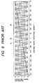
- FIG. 8 is a characteristic graph showing the relation between the steering wheel rotational angle and the voltage of each of the first to third angle detection signals, which are all sent from the rotary sensor, in a rotational angle detector based on the above-said rotary sensor.
- reference numeral 51 represents the first angle detection signal, 52 the second angle detection signal and 53 the third angle detection signal; this graph shows changes in the voltage of each of the first to third angle detection signals 51, 52, 53 in the whole range of steering wheel rotation ( ⁇ 720 degrees from the neutral position).
- the first angle detection signal 51 and the second angle detection signal 52 are sinusoidal waveform signals with the same maximum amplitude and the same cycle, between which there is a quarter-wave phase difference, where they both have a maximum voltage of 4.5 V and a minimum voltage of 0.5 V.
- the voltage is the minimum (0.5 V) at a rotational angle of -22.5 degrees from the neutral position (0 degree) and rotational angles decreasing from -22.5 degrees in decrements of -90 degrees, and at a rotational angle of +67.5 degrees and rotational angles from +67.5 degrees in increments of +90 degrees.
- the voltage is the minimum (0.5 V) at a rotational angle of 0 degree (neutral position) and rotational angles decreasing from 0 degree in decrements of -90 degrees and rotational angles increasing from 0 degree in increments of +90 degrees.
- the voltage linearly increases over the rotational angle range from -720 degrees to +720 degrees, with the minimum voltage (0.5 V) at -720 degrees of rotational angle and the maximum voltage (4.5 V) at +720 degrees of rotational angle.
- FIG. 9 is a fragmentary view of the characteristic graph in FIG. 8 where the part ranging from -90 degrees to +90 degrees is enlarged.
- 51U represents a virtually linear leading edge (gradient) for the first angle detection signal 51
- 51D a virtually linear trailing edge (gradient) for the first angle detection signal 51
- 52U a virtually linear leading edge (gradient) for the second angle detection signal 52
- 52D a virtually linear trailing edge (gradient)' for the second angle detection signal 52.
- the same other elements as those shown in FIG. 8 are designated with the same reference numerals.
- the control section detects the rotational direction from the neutral position (rotational angle of 0 degree) of the steering wheel according to the voltage of the third detection signal it has received. Concretely, if the voltage of the third detection signal-53 is over 2.5 V, it detects that the steering wheel has been turned in one direction (positive angle), while if the voltage of the third detection signal 53 is below 2.5 V, it detects that the steering wheel has been turned in the other direction (negative angle).
- the control section roughly determines a rotational angle as follows. As illustrated in FIG. 9, the whole rotational angle range of the steering wheel (for example, 1440 degrees, or ⁇ 720 degrees) is divided into segments named N-1, N, N+1 and so on with one segment (for example, 90 degrees) corresponding to one wavelength of the first angle detection signal 51 and second angle detection signal 52.
- the control section detects in which of the angle segments N-1, N, N+1 the voltage of the received third angle detection signal 53 falls, in order to determine a rough rotational angle. For instance, if the voltage of the third angle detection signal 53 is found to be 2.8 V, the control section determines that it is the angle segment N that corresponds to that voltage.
- the control section obtains the first voltage value V 1 and second voltage value V 2 , or points where the voltage of the received first angle detection signal 51 coincides with that of the second angle detection signal 52. Referring to the first voltage value V 1 and second voltage value V 2 thus obtained, the control section identifies either of the angle detection signals as a signal out of the V 1 -V 2 range and the other signal as a signal within the V 1 -V 2 range, in each sub-segment of the segment N.
- the control section decides whether the other angle detection signal within the V 1 -V 2 range is either the first angle detection signal 51 or the second angle detection signal 52. At the same time, the control section decides whether the one angle detection signal out of the V 1 -V 2 range is either smaller than the first voltage value V 1 or larger than the second voltage value V 2 . Also it determines in which one of the four sub-segments (the first sub-segment H1, second sub-segment H2, third sub-segment H3 and fourth sub-segment H4) of the angle segment N the other angle detection signal, which is within the V 1 -V 2 range, falls. In this way, the rotational angle of the steering wheel is determined more accurately by finding in which sub-segment (among the sub-segments H1 to H4 of the angle segment N) does the other angle detection signal fall.
- the part in the first sub-segment H1 corresponds to the linear leading edge (gradient) 51U of the first angle detection signal 51;
- the part in the second sub-segment H2 corresponds to the linear leading edge (gradient) 52U of the second angle detection signal 52;
- the part in the third sub-segment H3 corresponds to the linear trailing' edge (gradient) 51D of the first angle detection signal 51;
- the part in the fourth sub-segment H4 corresponds to the linear trailing edge (gradient) 52D of the second angle detection signal 52.
- control section finally determines the angle of the steering wheel from the first to third angle detection signals 51 to 53 it has received, and generates an angle set signal based on the determined angle.
- the control section when a rotary sensor (rotational angle detecting section) as suggested above is employed, the rotary sensor sends the first angle detection signal 51, second angle detection signal 52 and third angle detection signal 53 to the control section as the rotor turns.
- the control section first detects the rotor's rotational direction and rough rotational angle based on the amplitude (voltage) of the third angle detection signal 53, and then more accurately determines the rotor's rotational angle based on the linear gradient of the first and second angle detection signals 51 and 52. Therefore, the control section can detect the rotor's rotational angle and direction over a wide angle range with high accuracy and thus produce an angle set signal from the detection result with high accuracy.
- a rotational angle detector having the above-suggested rotary sensor directly uses the first angle detection signal 51, second angle detection signal 52 and third angle detection signal 53 to detect the rotational angle and direction of the rotor
- detection of rotational angle and direction detection is performed according to the incorrect angle detection signal and consequently an incorrect angle set signal is fed from the control section to the controller. If the controller has received the incorrect angle set signal, it fails to control the suspension system or traction control system of the vehicle properly; if this phenomenon continues, it will become difficult to control the vehicle properly.
- the present invention has been made in view of the above technical background; the primary object of the invention is to provide a rotational angle detector which eliminates the possibility of output of an incorrect angle set signal by promptly identifying the feed of an incorrect angle set signal, or by outputting an angle set signal with an abnormality signal added upon detection of an abnormality, in order to prevent incorrect control based on an incorrect angle set signal.
- a rotational angle detector comprises: a rotational angle detecting section which detects an angle detection signal correspondent to a rotational state of a rotor in a short cycle and feeds the angle detection signal to a control section; the control section which calculates the angle detection signal fed from the rotational angle detecting section and sends an angle set signal through a controller to a controlled system; and a memory which stores the angle detection signal temporarily and also stores an allowable maximum angle value for angle detection signals, wherein the control section has a means to make an output cycle for the angle set signal longer than a detection cycle for the angle detection signal and count a number of times when the angle detection signal as fed within the long output cycle for angle detection signals is beyond the allowable maximum angle value and, if the count is judged as being beyond a preset number, output an abnormality signal instead of the angle set signal.
- the memory stores the allowable maximum angle value for angle detection signals; and the control section counts the number of times when the angle detection signal as fed within a long output cycle for angle set signals is beyond the allowable maximum angle value and, if it decides that the count is above a preset number, outputs an abnormality signal in the next output-cycle for angle set signals instead of the angle set signal. Therefore, thanks to output of the abnormality signal, the user of the rotational angle detector can not only immediately be notified of the presence of an abnormality in the operation of the rotational angle detector but also avert the risk of the controlled system being improperly controlled due to the feed of an incorrect angle set signal.
- the detection cycle for angle detection signals be 400 microseconds or less and the output cycle for angle set signals be 10 milliseconds or less.
- variation per detection cycle is 0.8 degree or less because the maximum rotating rate of the steering wheel may be 2000 degrees/sec.
- This detection accuracy is much higher than the required detection accuracy for a product, or 1.5 degrees; in other words, abnormalities can be detected with high accuracy.
- the rotational angle detector it is desirable to judge the count (number of times when the angle detection signal is beyond the allowable maximum value) as being beyond the preset number when two out of three consecutive counts are found beyond the preset-number.
- the controlled system can be controlled in response only to an abnormality signal to be addressed, which arises from an abnormal operation, without responding to external noise or any other abnormal signal which need not be addressed, so that the controlled system can be controlled efficiently and smoothly.
- the rotational angle detector it is desirable to judge the count (number of times when the angle detection signal is beyond the allowable maximum value) as being beyond the preset number when six out of 64 consecutive counts are found beyond the preset number.
- the rotational angle detector comprises: a rotational angle detecting section which detects an angle detection signal correspondent to a rotational state of a rotor and feeds the angle detection signal to a control section; the control section which calculates the angle detection signal fed from the rotational angle detecting section to generate an angle set signal and sends the generated angle set signal through a controller to a controlled system; and a memory which stores an allowable maximum setting, wherein the control section has means to concurrently perform a first calculation step and a second calculation step for the angle detection signal fed from the rotational angle detecting section to generate a first angle set signal and a second angle set signal, calculate the difference between the first angle set signal and second angle set signal, compare the calculated difference with the allowable maximum setting, and if the calculated difference is judged as being above the allowable maximum setting, output an abnormality signal instead of the angle set signal.
- the memory stores the allowable maximum setting and the control section concurrently performs a first calculation step and a second calculation step for the angle detection signals fed from the rotational angle detecting section to generate a first angle set signal and a second angle set signal, calculates the difference between the first angle set signal and second angle set signal, compares the calculated difference with the allowable maximum setting read from the memory, and the calculated difference is judged as being below the allowable maximum setting, generates and outputs a given angle set signal at the time of angle set signal output, while if the calculated difference is judged as being above the allowable maximum setting, generates and outputs an abnormality signal in addition to a given angle set signal at the time of angle set signal output.
- the user of the rotational angle detector can not only immediately be notified of the presence of an abnormality in the operation of the rotational angle detector but also avert the risk of the controlled system being improperly controlled due to the feed of an incorrect angle set signal.
- control section in the rotational angle detector, it is desirable for the control section to perform the first calculation step and the second calculation step using different lookup tables.
- control section in the rotational angle detector, it is desirable for the control section to perform the first calculation step and the second calculation step using different algorithms.
- the control section in the rotational angle detector, it is desirable for the control section to detect an angle detection signal in a short cycle and output the angle set signal in a cycle longer than the detection cycle for angle detection signals.
- the first calculation step and the second-calculation step be performed by different control sections.
- FIG. 1 is a block diagram showing the main structure of a rotational angle detector according to the first embodiment of the present invention.
- the rotational angle detector is used to detect the rotational angle of the steering wheel of a vehicle.
- the rotational angle detector comprises: a rotational angle detecting section 1; a control section (CPU) 2 incorporating an angle calculating section 8 and a decision section 9; a memory 3; an abnormality signal generator 4; a bus line 5 for LAN (local area network) ; a controller 6; and a controlled system 7.
- the rotational angle detecting section 1 is, for example, a rotary sensor like the one shown in FIG. 10A and FIG. 10B which comprises a case 71, a rotor 72, a rotary shaft 73, a bearing 74, a worm gear 75, a slider 76, a first magnet 77 1 , a second magnet 77 2 , a first Hall element 78 1 , a second Hall element 78 2 , a third Hall element 78 3 , and a circuit board 79.
- the rotor 72 is connected with the steering shaft of the vehicle at its center and there are many gear teeth on its circumference.
- the rotary shaft 73, around which the worm gear 75 is fitted, rotates in conjunction with the worm gear 75.
- the screw grooves in the outer surface of the rotary shaft 73 engage with the screw grooves in the inner surface of the slider 76 so that the slider 76 slides in the axial direction of the rotary shaft 73 as the rotary shaft 73 turns.
- the rotary shaft 73 also turns by the mediation of the worm gear 75 at a prescribed rotation ratio with respect to the rotor 72.
- the worm gear 75 has a cylindrical magnet holder 75A at one end of it and the cylindrical first magnet 77 1 is fitted on the circumference of the magnet holder 75A.
- the slider 76 has a planar second magnet 77 2 attached onto its outer surface.
- the first Hall element 78 1 and the second Hall element 78 2 are located adjacent to the outer surface of the first magnet 77 1 , forming an angle of approximately 90 degrees with respect to the central axis of the first magnet 77 1 .
- the third Hall element 78 3 is located adjacent to the outer surface of the second magnet 77 2 .
- the rotational angle detecting section 1 a series of operations are performed as follows. As the steering wheel turns, the steering shaft turns simultaneously, which makes the first magnet 77 1 come closer periodically, causing a magnetic flux change. This magnetic flux change is detected by the first Hall element 78 1 and second Hall element 78 2 . Likewise, the magnetic flux change caused by the second magnet 77 2 coming closer periodically is detected by the third Hall element 78 3 . Based on the above-mentioned detection, the first Hall element 78 1 , second Hall element 78 2 , and third Hall element 78 3 generate a first angle detection signal, a second one, and a third one, respectively. The first to third angle detection signals thus generated are sent to the control section 2 in a short cycle.
- the first to third angle detection signals are the first angle detection signal 51, second angle detection signal 52 and third angle detection signal 53 as shown in FIG. 8, respectively, and each of them has an amplitude corresponding to the rotational angle of the steering shaft.
- the memory 3 stores a maximum angle detection signal which can be fed to the control section 2, namely an allowable maximum angle value.
- the abnormality signal generator 4 generates an abnormality signal under the control of the control section 2. This embodiment assumes that the controlled system 7 is a suspension system or traction control system in a vehicle.
- the output end of the rotational angle detection section 1 is connected to the input end of the control section 2.
- the control section 2 is connected to the memory 3 and the abnormality signal generator 4 and also its output end is connected to the input end of the controller 6 through the local area network bus line 5.
- the control end of the controller 6 is connected to the controlled system 7.
- the rotational angle detecting section 1 As the operator turns the steering wheel, the rotational angle detecting section 1 generates a first angle detection signal 51 and a second angle detection signal 52, which are sent to the control section 2, as illustrated in FIG. 5.
- the peak-to-peak amplitude is 4.0 V
- the cycle is 90 degrees in terms of steering wheel rotational angle
- the phase difference is a quarter of the wavelength; namely 22.5 degrees in terms of steering wheel rotational angle.
- FIG. 2 shows an example of input timings for an angle detection signal to be fed to the control section 2, and output timings for an angle set signal to be outputted from the control section 2.
- the black dots in the upper portion represent when an angle detection signal is inputted, while the black dots in the lower portion (second line) represent when an angle set signal is outputted.
- the horizontal axis represents time in seconds.
- angle detection signals are successively fed to the control section with a short cycle of 400 microseconds ( ⁇ sec), while angle set signals are successively outputted from the control section 2 with a longer cycle of 10 milliseconds (msec).
- the control section 2 outputs an angle set signal every time an angle detection signal is inputted 25 times.
- FIG. 3 and FIG. 4 are flowcharts showing the operational process concerning how the control section 2 processes the received angle detection signal and outputs an angle set signal.
- FIG. 3 shows the operational steps (the first half of the process) in which an angle value is calculated from the received angle detection signal and stored in the memory 3 temporarily; and
- FIG. 4 shows the operational steps (the second half of the process) about how the angle value read from the memory 3 is used to output an angle set signal.
- step S1 the control section 2 decides whether 400 ⁇ sec have elapsed after reception of the previous angle detection signal. If yes, or if it decides that 400 ⁇ sec have elapsed after reception of the previous angle detection signal, then it goes to the next step S2; on the other hand, if no, or if it decides that 400 ⁇ sec have not elapsed after reception of the previous angle detection signal, then step S1 is carried out repeatedly.
- control section 2 obtains the newest angle detection signal from the rotational angle detecting section 1.
- step S3 the control section 2 decides whether or not the angle detection signal just obtained is below the allowable maximum angle value stored in the memory 3. If yes, or if it decides that the angle detection signal just obtained is below the allowable maximum angle value, then it jumps to step S5; on the other hand, if no, or if it decides that the angle detection signal just obtained is not below the allowable maximum angle value, then it goes to the next step S4.
- step S4 the control section 2 sets a tentative error flag for the obtained angle detection signal.
- step S5 the control section 2 calculates the rotational angle from the obtained angle detection signal using its internal angle calculating section 8.
- step S6 the control section 2 decides whether or not the calculated angle value is below the allowable maximum angle value stored in the memory 3. If yes, or if it decides that the calculated angle is below the allowable maximum angle value, then it jumps to step S8; on the other hand, if no, or if it decides that the calculated angle is not below the allowable maximum angle value, then it goes to the next step S7.
- control section 2 sets a tentative error flag for the calculated angle value.
- step S8 using its internal decision section 9, the control section 2 decides whether or not the angle detection signals or rotational angle values for which a tentative error flag has been set are at most two (i.e. 0, 1 or 2) out of three successively fed ones. If yes, or if it decides that such signals or values are 2 or less out of the three ones, then it jumps to step S10; on the other hand, if no, or if it decides that such signals or values are not 2 or less out of the three ones, then it goes to the next step S9.
- control section 2 converts a tentative flag set for the angle detection signals or rotational angle values into a permanent error flag.
- step S10 using its internal decision section 9, the control section 2 decides whether or not the tentative angle detection signals or rotational angle values for which a tentative error flag has been set are six ore less out of 64 successively fed ones. If yes, or if it decides that the number of such signals or values out of the 64 successively supplied ones is 6 or less, then it jumps to step S12; on the other hand, if no, or if it decides that the number of such signals or values out of the 64 successively supplied ones is more than 6, then it goes to the next step S11.
- control section 2 converts a tentative flag temporarily set for the angle detection signals or rotational angle values into a permanent error flag.
- control section 2 sends the angle data calculated at step S5 to the memory 3, where it is stored.
- step S13 the control section 2 decides whether or not the vehicle's key has been turned off. If yes, or if it decides that the key has been turned off, then this series of steps is finished; on the other hand, if no, or if it decides that the key has not been turned off yet, then it returns to the first step S1 and the procedure from step S1 is repeated.
- step S21 the control section 2 decides whether or not 10 msec have elapsed after output of the previous angle set signal. If yes, or if it decides that 10 msec have elapsed after output of the previous angle set signal, then it goes to the next step S22; on the other hand, if no, or if it decides that 10 msec have not elapsed yet after output of the previous angle set signal, then step S21 is carried out repeatedly.
- control section 2 reads and obtains the newest angle value from the memory 3.
- the control section 2 decides whether or not a tentative error flag has been set for the obtained newest angle value. If no, or if it decides that a tentative error flag has not been set for the newest angle value, then it jumps to step S25; on the other hand, if yes, or if it decides that a tentative error flag has been set for the newest angle value, then it goes to the next step S24.
- step S24 the control section 2 reads and obtains the last angle value from the memory 3. After obtaining that angle value, it returns to step S23 and the procedure from step S23 is repeated.
- step S25 the control section 2 decides whether or not a permanent error flag has been set for the obtained angle value. If no, or if it decides that a permanent error flag has not been set for the obtained angle value, then it goes to the next step S26; on the other hand, if yes, or if it decides that a permanent error flag has been set for the obtained angle value, then it jumps to step S27.
- control section 2 uses the obtained angle value, the control section 2 generates an angle set signal and sends the generated angle set signal to the local area network bus line 5.
- control section 2 drives the abnormality signal generator 4 to generate an abnormality signal and sends the generated abnormality signal to the local area network bus line 5.
- step S28 the control section 2 decides whether or not the vehicle's key has been turned off. If yes, or if it decides that the key has been turned off, then this series of steps as shown in the flowchart is finished; on the other hand, if no, or if it decides that the key has not been turned off yet, then it returns to the first step S21 and the procedure from step S21 is repeated.
- the controller 6 controls the vehicle's suspension system or traction control system as a controlled system 7 according to the received angle set signal.
- an abnormality signal is sent from the control section 2 to the local area network bus line 5, the abnormality signal is transmitted to an alarm unit or display unit (neither shown) which is connected with the local area network bus line 5, and the alarm unit issues an alarm or the display unit shows the presence of an abnormal condition, so a person in the vehicle can immediately notice the presence of an abnormality in the operation of the rotational angle detector.
- the control section 2 outputs an abnormality signal, no angle set signal is outputted and therefore it is unlikely that the controlled system 7 is improperly controlled due to output of an incorrect angle set signal.
- control section 2 eliminates the possibility of output of an incorrect angle value for the following reason. Even if a tentative error flag has been set for an angle value or, for example, if the angle value has been decided to be at least incorrect due to temporary external disturbance, noise or other reason though it has not been decided to be a permanent error, the angle value for which the tentative error flag has been set through steps S23 and S24 is not outputted but the stored previous angle data is traced back to pick up and output the angle data which has been decided as normal; therefore, the possibility of output of abnormal angle data is eliminated.
- the rotational angle detector according to the first embodiment has been explained on the assumption that the input short cycle for angle detection signals sent from the control section 2 is 400 ⁇ sec, and the output long cycle for angle detection signals outputted from the control section 2 is 10 msec; however, the input short cycle and output long cycle for angle detection signals according to the present invention are not limited to 400 ⁇ sec and 10 msec respectively. It is needless to say that other cycle times near to 400 ⁇ sec and 10 msec may be used.
- the rotational angle detector according to the above embodiment has been explained on the assumption that a permanent error flag is set for an angle value on condition that in the short run the angle detection signals or rotational angle values for which a tentative error flag has been set are two or more out of three successively fed ones and in the long run the angle detection signals or rotational angle values for which a tentative error flag has been set are six or more out of 64 successively fed ones.
- the condition for a permanent flag to be set for an angle value is not limited thereto; the frequency of such signals or angle values may be any number near to the above numbers.
- the rotational angle detector according to the above embodiment has been explained on the assumption that it is used to detect the rotational angle of the steering wheel of a vehicle; however, the application of the rotational angle detector according to the present invention is not limited to rotational angle detection of such a steering wheel. It may also be used to detect the rotational angle of a device similar to a steering wheel.
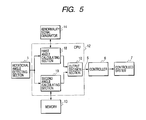
- FIG. 5 is a block diagram showing the main structure of a rotational angle detector according to the second embodiment of the present invention.
- the rotational angle detector is used to detect the rotational angle of the steering wheel of a vehicle.
- the rotational angle detector comprises: a rotational angle detecting section 1; a control section (CPU) 12 incorporating a first angle calculating section 18, a second angle calculating section 19 and an output decision section 10; a memory 13; an abnormality signal generator 14; a bus line 5 for LAN (local area network) ; a controller 6; and a controlled system 7.
- a series of operations are performed as follows. As the steering wheel turns, the steering shaft turns simultaneously, which makes the first magnet 77 1 of the rotary sensor shown in FIG. 10A and FIG. 10B come closer periodically, causing a magnetic flux change. This magnetic flux change is detected by the first Hall element 78 1 and second Hall element 78 2 . Likewise, the magnetic flux change caused by the second magnet 77 2 coming closer periodically is detected by the third Hall element 78 3 . Based on the above-mentioned detection, the first Hall element 78 1 , second Hall element 78 2 , and third Hall element 78 3 generate a first angle detection signal, a second one, and a third one, respectively.
- the first to third angle detection signals thus generated are sent to the control section 12 in a short cycle.
- the first angle detection signal 51, second angle detection signal 52 and third angle detection signal 53 as shown in FIG. 8 each have an amplitude correspondent to the rotational angle of the steering shaft.
- the memory 13 stores a possible maximum output of difference between the first angle set signal and second angle set signal, namely an allowable maximum setting.
- the abnormality signal generator 14 generates an abnormality signal under the control of the control section 12.
- the local area network (LAN) bus line 5 is installed in the vehicle. This embodiment assumes that the controlled system 7 is a suspension system or automatic transmission system in a vehicle.
- the output end of the rotational angle detection section 1 is connected to the input end of the control section 12.
- the control section 12 is connected to the memory 13 and the abnormality signal generator 14 and also its output end is connected to the input end of the controller 6 through the local area network bus line 5.
- the control end of the controller 6 is connected to the controlled system 7.
- the input end of the first angle calculating section 18 is connected to the input end of the second angle calculating section 19 and its output end is connected to the first input end of the output decision section 10.
- the output end of the second angle calculating section 19 is connected to the second input end of the output decision section 10.
- the rotational angle detecting section 1 As the operator turns the steering wheel, the rotational angle detecting section 1 generates a first angle detection signal 51 and a second angle detection signal 52, which are sent to the control section 12, as illustrated in FIG. 8.
- the peak-to-peak amplitude is 4.0 V
- the cycle is 90 degrees in terms of steering wheel rotational angle
- the phase difference is a quarter of the wavelength, namely 22.5 degrees in terms of steering wheel rotational angle.
- angle detection signals are successively supplied to the control section 12 with a short cycle of 400 microseconds ( ⁇ sec), while angle set signals are successively outputted from the control section 12 with a longer cycle of 10 milliseconds (msec).
- ⁇ sec microseconds
- msec milliseconds
- the control section 12 makes the received angle detection signal enter the first angle calculating section 18 and second angle calculating section 19 simultaneously.
- the first angle calculating section 18 and second angle calculating section 19 make calculation for the entered angle detection signal in different modes as stated later, so that the first angle calculating section 18 generates a first angle set signal and the second angle calculating section 19 generates a second angle set signal and the generated first and second angle set signals are sent to the output decision section 10.
- the output decision section 10 calculates the difference between the first angle set signal and second angle set signal and compares the calculated difference with the allowable maximum setting read from the memory 13.
- the control section 12 selects either the first angle set signal or the second angle set signal, whichever represents a more desirable condition, when it is time to output an angle set signal; for example, if it selects the first angle set signal, it outputs the selected first angle set signal to the local area network bus line 5 as a normal angle set signal.
- the control section 12 selects either the first angle set signal or the second angle set signal, whichever represents a more desirable condition, and also activates the abnormality signal generator 4 to generate an abnormality signal; then it outputs the selected angle set signal and the generated abnormality signal to the local area network bus line 5.
- the angle set signal and abnormality signal sent from the control section 12 to the local area network bus line 5 are sent to the controller 6.
- the controller 6 controls the vehicle's suspension system or traction control system as the controlled system 7 according to the angle set signal it has received.
- the abnormality signal sent from the control section 12 to the local area network bus line 5 is sent to an alarm unit or display unit (neither shown) which is connected with the local area network bus line 5.
- the alarm unit issues an alarm or the display unit shows the presence of an abnormal condition.
- the control section 12 outputs an abnormality signal as well as an angle set signal, it is unlikely that the controlled system 7 is controlled improperly due to output of an incorrect angle set signal.
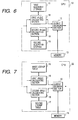
- FIG. 6 and FIG. 7 are block diagrams showing the structure of the control section 12 shown in FIG. 5 in more detailed form; FIG. 6 shows a first example thereof and FIG. 7 is a second example thereof.
- FIG. 6 and FIG. 7 the same components as those shown in FIG. 5 are designated with the same reference numerals.
- control section 12 as the first example incorporates a first algorithm storage 11 and a second algorithm storage 15 where the former is connected with the first angle calculating section 18 and the latter is connected with the second angle calculating section 19 and contains an algorithm different from that stored in the first algorithm storage 11; and the output decision section 10 is connected with the memory 13.
- control section 22 as the second example incorporates a first lookup table 16 and a second lookup table 17 where the former is connected with the first angle calculating section 18 and the latter is connected with the second angle calculating section 19 and different from the first lookup table 16; and the output decision section 10 is connected with the memory 13.
- the first algorithm storage 11 stores an algorithm which detects the angle in terms of sin -1 ⁇ according to angle detection signals from the rotational angle detecting section 1 and the second algorithm storage 15 stores an algorithm which detects the angle in terms of cos -1 ⁇ according to angle detection signals from the rotational angle detecting section 1.
- the first algorithm storage 11 detects the angle in terms of sin -1 ⁇ according to angle detection signals from the rotational angle detecting section 1; based on the detected angle data, the first angle calculating section 18 generates a first angle set signal and sends it to the output decision section 10, while the second algorithm storage 15 generates a second angle set signal 19 based on the angle data detected in terms of cos -1 ⁇ in the second algorithm storage 15 and sends it to the output decision section 10.
- the output decision section 10 calculates the difference between the first angle set signal and second angle set signal which it has received, and compares the calculated difference with the allowable maximum setting read from the memory 13.
- the control section 12 selects either the first angle set signal or the second angle set signal, whichever represents a more desirable condition; for example, if it selects the first angle set signal, it outputs the selected first angle set signal through the local area network bus line 5 to the controller 6.
- the control section 12 selects either the first angle set signal or the second angle set signal, whichever represents a more desirable condition (for example, it selects an angle set signal with a voltage nearer to 2.5 V) and outputs the selected angle set signal as a normal angle set signal through the local area network bus line 5 to the controller 6; in addition, it activates the abnormality signal generator 14 to generate an abnormality signal and sends the selected angle set signal and the abnormality signal through the local area network bus line 5 to the controller 6.
- an angle set signal carrying angle data detected with high accuracy is constantly fed and if an abnormality occurs in the operation of the rotational angle detector, a warning is immediately given; furthermore, the control section 12 outputs an abnormality signal in addition to a properly selected angle set signal. Therefore, it is unlikely that the controlled system 7 is improperly controlled due to output of an incorrect angle set signal.
- these tables 16 and 17 are structurally different and created as different tables though they are mathematically or theoretically identical.
- the first and second tables 16 and 17 are created in this way and incorporated in a certain product, even if a fault occurs for some reason, it is very unlikely that both the tables contain faults. This means that an abnormality can be detected with higher accuracy because a decision about output is made using each of the first and second tables 16 and 17.
- the rotational angle detector according to the above embodiment has been explained on the assumption that the input cycle of angle detection signals being fed to the control section 22 is 400 microseconds and the output cycle of angle detection signals being outputted from the control section 22 is 10 milliseconds; however, the input and output cycles for angle detection signals according to the present invention are not limited to 400 microseconds and 10 milliseconds, respectively. It is needless to say that other cycle times near to 400 microseconds and 10 milliseconds may be used.
- the rotational angle detector according to the above embodiment has been explained on the assumption that it is used to detect the rotational angle of the steering wheel of a vehicle; however, the application of the rotational angle detector according to the present invention is not limited to rotational angle detection of such a steering wheel. It may also be used to detect the rotational angle of a device similar to a steering wheel.
- the memory stores an allowable maximum setting as the maximum output data which may express the difference between the first angle set signal and second angle set signal; and the control section concurrently performs a first calculation step and a second calculation step for the angle detection signals fed from the rotational angle detecting section to generate a first angle set signal and a second angle set signal, calculates the difference between the generated first angle set signal and second angle set signal, compares the calculated difference with the allowable maximum setting read from the memory, and if the calculated difference is judged as being below the allowable maximum setting, generates and outputs a given angle set signal when it is time to output an angle set signal; on the other hand, if the calculated difference is judged as being above the allowable maximum setting, generates and outputs an abnormality signal in addition to a given angle set signal when it is time to output an angle set signal.
- the user of the rotational angle detector can not only immediately be notified of the presence of an abnormality in the operation of the rotational angle detector but also avert the risk of the controlled system being improperly controlled due to the feed of an incorrect angle set signal.
- the memory stores the allowable maximum angle value for angle detection signals; and the control section counts the number of times when the angle detection signal as fed within the long output cycle for angle set signals is beyond the allowable maximum signal and, if the count is judged as being above a preset number, outputs an abnormality signal instead of the angle set signal in the next cycle for angle set signal output. Therefore, thanks to output of the abnormality signal, the user of the rotational angle detector can not only immediately be notified of the presence of an abnormality in the operation of the rotational angle detector but also avert the risk of the controlled system being improperly controlled due to the feed of an incorrect angle set signal.
Landscapes
- Physics & Mathematics (AREA)
- General Physics & Mathematics (AREA)
- Engineering & Computer Science (AREA)
- Chemical & Material Sciences (AREA)
- Combustion & Propulsion (AREA)
- Transportation (AREA)
- Mechanical Engineering (AREA)
- Measurement Of Length, Angles, Or The Like Using Electric Or Magnetic Means (AREA)
- Length Measuring Devices With Unspecified Measuring Means (AREA)
- Transmission And Conversion Of Sensor Element Output (AREA)
Applications Claiming Priority (4)
| Application Number | Priority Date | Filing Date | Title |
|---|---|---|---|
| JP2001229847A JP2003042752A (ja) | 2001-07-30 | 2001-07-30 | 回転角検出装置 |
| JP2001229859 | 2001-07-30 | ||
| JP2001229847 | 2001-07-30 | ||
| JP2001229859A JP2003042753A (ja) | 2001-07-30 | 2001-07-30 | 回転角検出装置 |
Publications (3)
| Publication Number | Publication Date |
|---|---|
| EP1281601A2 true EP1281601A2 (de) | 2003-02-05 |
| EP1281601A3 EP1281601A3 (de) | 2004-02-04 |
| EP1281601B1 EP1281601B1 (de) | 2009-06-03 |
Family
ID=26619551
Family Applications (1)
| Application Number | Title | Priority Date | Filing Date |
|---|---|---|---|
| EP02016792A Expired - Lifetime EP1281601B1 (de) | 2001-07-30 | 2002-07-26 | Die unsachgemässe Regelung eines geregelten Systems verhindernder Drehwinkelsensor |
Country Status (3)
| Country | Link |
|---|---|
| US (1) | US6778939B2 (de) |
| EP (1) | EP1281601B1 (de) |
| DE (1) | DE60232483D1 (de) |
Families Citing this family (9)
| Publication number | Priority date | Publication date | Assignee | Title |
|---|---|---|---|---|
| JP4143436B2 (ja) * | 2003-02-17 | 2008-09-03 | トヨタ自動車株式会社 | 磁気式回転検出装置 |
| US7207412B2 (en) * | 2004-02-17 | 2007-04-24 | Denso Corporation | Motor-driven power steering system |
| GB0620307D0 (en) * | 2006-10-16 | 2006-11-22 | Ami Semiconductor Belgium Bvba | Auto-calibration of magnetic sensor |
| ES2676508T3 (es) * | 2007-06-06 | 2018-07-20 | Hydro-Aire, Inc. | Sensor de posición angular |
| JP4926299B1 (ja) * | 2011-03-22 | 2012-05-09 | 三菱電機株式会社 | プログラマブルロジックコントローラ |
| CN102620705A (zh) * | 2012-04-01 | 2012-08-01 | 中联重科股份有限公司 | 回转机构的回转角度检测方法、装置、系统与工程机械 |
| JP6363559B2 (ja) * | 2015-06-10 | 2018-07-25 | ファナック株式会社 | 異物の侵入を検出可能な回転角度検出器 |
| JP6416983B1 (ja) * | 2017-05-22 | 2018-10-31 | ファナック株式会社 | 回転軸の角度較正方法および角度較正プログラム |
| KR102944237B1 (ko) * | 2020-07-29 | 2026-03-30 | 에이치엘만도 주식회사 | 조향 제어 시스템, 조향 제어 장치 및 방법 |
Family Cites Families (9)
| Publication number | Priority date | Publication date | Assignee | Title |
|---|---|---|---|---|
| US4996657A (en) * | 1988-03-18 | 1991-02-26 | Honda Giken Kogyo K.K. | Steering angle detecting system for automotive vehicles |
| JPH01270627A (ja) | 1988-04-22 | 1989-10-27 | Hitachi Ltd | トルクセンサ保護装置 |
| JP2694344B2 (ja) | 1988-06-17 | 1997-12-24 | 株式会社豊田中央研究所 | 車両用舵角制御装置 |
| DE4130142A1 (de) | 1991-09-11 | 1993-03-18 | Fichtel & Sachs Ag | Einrichtung und verfahren zur bestimmung eines korrekturwinkels fuer einen lenkwinkelsensor eines fahrzeugs |
| EP0794410B1 (de) * | 1996-03-04 | 2003-06-25 | Alps Electric Co., Ltd. | Kodiererplatte für Winkelgeber |
| DE19651771C1 (de) * | 1996-12-12 | 1998-04-16 | Trw Fahrzeugelektrik | Absolutwertgeber, insbesondere Drehgeber zur Erfassung des Lenkwinkels eines Kraftfahrzeugs |
| JP3816679B2 (ja) * | 1998-09-17 | 2006-08-30 | 株式会社東海理化電機製作所 | 回転角度検出装置 |
| DE19849108C2 (de) | 1998-10-24 | 2001-12-13 | Fritz Kuebler Gmbh Zaehl Und S | Drehgeber |
| JP2001174289A (ja) | 1999-12-17 | 2001-06-29 | Alps Electric Co Ltd | 回転角検出装置 |
-
2002
- 2002-07-23 US US10/200,887 patent/US6778939B2/en not_active Expired - Fee Related
- 2002-07-26 EP EP02016792A patent/EP1281601B1/de not_active Expired - Lifetime
- 2002-07-26 DE DE60232483T patent/DE60232483D1/de not_active Expired - Fee Related
Non-Patent Citations (1)
| Title |
|---|
| None |
Also Published As
| Publication number | Publication date |
|---|---|
| EP1281601A3 (de) | 2004-02-04 |
| DE60232483D1 (de) | 2009-07-16 |
| US6778939B2 (en) | 2004-08-17 |
| EP1281601B1 (de) | 2009-06-03 |
| US20030023400A1 (en) | 2003-01-30 |
Similar Documents
| Publication | Publication Date | Title |
|---|---|---|
| EP2472232B1 (de) | Rotationswinkelerkennungsvorrichtung | |
| US7471080B2 (en) | Magnetic absolute encoder | |
| CN102570943B (zh) | 旋转角检测装置 | |
| US6615152B2 (en) | Abnormality detecting method and device for position detecting device, and electric power steering device | |
| US6240349B1 (en) | Electric power steering apparatus | |
| EP1281601B1 (de) | Die unsachgemässe Regelung eines geregelten Systems verhindernder Drehwinkelsensor | |
| US9013179B2 (en) | Angle detecting device | |
| US9823094B2 (en) | Rotation detection device and bearing unit equipped with rotation detection device | |
| CA2380280A1 (en) | Shaft voltage and current monitoring system | |
| EP1850137B1 (de) | Vorrichtung zum Messen von Rotationspositionen | |
| KR20110126758A (ko) | 차량에 대한 타이어 위치를 결정하는 방법 및 장치 | |
| KR20050021942A (ko) | 이상 검출기를 포함한 각도 위치 판정 장치 | |
| JP3460587B2 (ja) | 回転角検出装置の異常を検出する異常検出装置 | |
| US10527467B2 (en) | Rotation angle detector which can detect entry of foreign substances | |
| EP1604883B1 (de) | Winkel- und Drehmomentmesseinrichtung | |
| JP2009276240A (ja) | 回転角検出装置 | |
| JPH06174576A (ja) | トルク検出装置 | |
| JP2006003281A (ja) | モーメント検出装置、タイヤ発生力検出装置、及び車輪異常検知装置 | |
| EP4696990A1 (de) | Erkennung von mechanischen rundlauffehlern | |
| JP2003042752A (ja) | 回転角検出装置 | |
| JP3575319B2 (ja) | トルクセンサ | |
| JP7599657B2 (ja) | 絶対角度位置検出方法及び装置 | |
| JP2004184326A (ja) | 回転角度検出装置 | |
| JP2000039335A (ja) | 回転機の回転角計測装置 | |
| JP2019078750A (ja) | マルチターンロータリエンコーダ及びマルチターンロータリエンコーダを作動させるための方法 |
Legal Events
| Date | Code | Title | Description |
|---|---|---|---|
| PUAI | Public reference made under article 153(3) epc to a published international application that has entered the european phase |
Free format text: ORIGINAL CODE: 0009012 |
|
| AK | Designated contracting states |
Designated state(s): AT BE BG CH CY CZ DE DK EE ES FI FR GB GR IE IT LI LU MC NL PT SE SK TR |
|
| AX | Request for extension of the european patent |
Extension state: AL LT LV MK RO SI |
|
| PUAL | Search report despatched |
Free format text: ORIGINAL CODE: 0009013 |
|
| AK | Designated contracting states |
Kind code of ref document: A3 Designated state(s): AT BE BG CH CY CZ DE DK EE ES FI FR GB GR IE IT LI LU MC NL PT SE SK TR |
|
| AX | Request for extension of the european patent |
Extension state: AL LT LV MK RO SI |
|
| RIC1 | Information provided on ipc code assigned before grant |
Ipc: 7G 01D 3/08 B Ipc: 7G 01D 5/244 B Ipc: 7B 62D 5/04 B Ipc: 7B 62D 15/02 A |
|
| 17P | Request for examination filed |
Effective date: 20040212 |
|
| AKX | Designation fees paid |
Designated state(s): DE GB SE |
|
| 17Q | First examination report despatched |
Effective date: 20061201 |
|
| GRAP | Despatch of communication of intention to grant a patent |
Free format text: ORIGINAL CODE: EPIDOSNIGR1 |
|
| GRAS | Grant fee paid |
Free format text: ORIGINAL CODE: EPIDOSNIGR3 |
|
| GRAA | (expected) grant |
Free format text: ORIGINAL CODE: 0009210 |
|
| AK | Designated contracting states |
Kind code of ref document: B1 Designated state(s): DE GB SE |
|
| REG | Reference to a national code |
Ref country code: GB Ref legal event code: FG4D |
|
| REF | Corresponds to: |
Ref document number: 60232483 Country of ref document: DE Date of ref document: 20090716 Kind code of ref document: P |
|
| PG25 | Lapsed in a contracting state [announced via postgrant information from national office to epo] |
Ref country code: SE Free format text: LAPSE BECAUSE OF FAILURE TO SUBMIT A TRANSLATION OF THE DESCRIPTION OR TO PAY THE FEE WITHIN THE PRESCRIBED TIME-LIMIT Effective date: 20090903 |
|
| PGFP | Annual fee paid to national office [announced via postgrant information from national office to epo] |
Ref country code: GB Payment date: 20090708 Year of fee payment: 8 Ref country code: DE Payment date: 20090730 Year of fee payment: 8 |
|
| PLBE | No opposition filed within time limit |
Free format text: ORIGINAL CODE: 0009261 |
|
| STAA | Information on the status of an ep patent application or granted ep patent |
Free format text: STATUS: NO OPPOSITION FILED WITHIN TIME LIMIT |
|
| 26N | No opposition filed |
Effective date: 20100304 |
|
| GBPC | Gb: european patent ceased through non-payment of renewal fee |
Effective date: 20100726 |
|
| PG25 | Lapsed in a contracting state [announced via postgrant information from national office to epo] |
Ref country code: DE Free format text: LAPSE BECAUSE OF NON-PAYMENT OF DUE FEES Effective date: 20110201 |
|
| REG | Reference to a national code |
Ref country code: DE Ref legal event code: R119 Ref document number: 60232483 Country of ref document: DE Effective date: 20110201 |
|
| PG25 | Lapsed in a contracting state [announced via postgrant information from national office to epo] |
Ref country code: GB Free format text: LAPSE BECAUSE OF NON-PAYMENT OF DUE FEES Effective date: 20100726 |