EP1281306A1 - Anbaueinrichtung, Fahrzeug und Verfahren - Google Patents
Anbaueinrichtung, Fahrzeug und Verfahren Download PDFInfo
- Publication number
- EP1281306A1 EP1281306A1 EP02017048A EP02017048A EP1281306A1 EP 1281306 A1 EP1281306 A1 EP 1281306A1 EP 02017048 A EP02017048 A EP 02017048A EP 02017048 A EP02017048 A EP 02017048A EP 1281306 A1 EP1281306 A1 EP 1281306A1
- Authority
- EP
- European Patent Office
- Prior art keywords
- attachment
- vehicle
- end region
- lifting arm
- add
- Prior art date
- Legal status (The legal status is an assumption and is not a legal conclusion. Google has not performed a legal analysis and makes no representation as to the accuracy of the status listed.)
- Granted
Links
- 238000000034 method Methods 0.000 title claims abstract description 7
- 238000012423 maintenance Methods 0.000 claims abstract description 5
- 230000008878 coupling Effects 0.000 abstract description 3
- 238000010168 coupling process Methods 0.000 abstract description 3
- 238000005859 coupling reaction Methods 0.000 abstract description 3
- 230000000875 corresponding effect Effects 0.000 description 3
- 210000002414 leg Anatomy 0.000 description 2
- 229910000831 Steel Inorganic materials 0.000 description 1
- 230000002349 favourable effect Effects 0.000 description 1
- 210000003746 feather Anatomy 0.000 description 1
- 238000009434 installation Methods 0.000 description 1
- 238000004519 manufacturing process Methods 0.000 description 1
- 239000010959 steel Substances 0.000 description 1
- 230000002195 synergetic effect Effects 0.000 description 1
- 210000000689 upper leg Anatomy 0.000 description 1
Images



Classifications
-
- A—HUMAN NECESSITIES
- A01—AGRICULTURE; FORESTRY; ANIMAL HUSBANDRY; HUNTING; TRAPPING; FISHING
- A01D—HARVESTING; MOWING
- A01D34/00—Mowers; Mowing apparatus of harvesters
- A01D34/01—Mowers; Mowing apparatus of harvesters characterised by features relating to the type of cutting apparatus
- A01D34/412—Mowers; Mowing apparatus of harvesters characterised by features relating to the type of cutting apparatus having rotating cutters
- A01D34/63—Mowers; Mowing apparatus of harvesters characterised by features relating to the type of cutting apparatus having rotating cutters having cutters rotating about a vertical axis
- A01D34/64—Mowers; Mowing apparatus of harvesters characterised by features relating to the type of cutting apparatus having rotating cutters having cutters rotating about a vertical axis mounted on a vehicle, e.g. a tractor, or drawn by an animal or a vehicle
-
- A—HUMAN NECESSITIES
- A01—AGRICULTURE; FORESTRY; ANIMAL HUSBANDRY; HUNTING; TRAPPING; FISHING
- A01D—HARVESTING; MOWING
- A01D2101/00—Lawn-mowers
Definitions
- the invention relates to an attachment device for detachable Attachment of an attachment to a vehicle, with one at least essentially horizontally extending retaining bolts, which is provided on the attachment, and at least one at least essentially rigid lifting arm with a first End area for swiveling attachment to one Vehicle frame, a vehicle, in particular a vehicle for Lawn, garden and property maintenance, as well as a method for Attaching an attachment, especially a mower a vehicle.
- Vehicles and especially vehicles for lawn, garden and Land maintenance, such as lawn tractors or Ride-on mowers are common with attachments, such as Mowers, provided. These attachments are with the vehicle by means of one or more attachment devices connected to and from the vehicle can be broken down.
- US-A-3,948,025 discloses a one-through lawn tractor a pair of lifting arms formed lifting frames, the lifting arms swiveling with a tractor frame and a pair of rear brackets on a mower or attachment are connected. At a front area are laterally spaced mounting brackets to hold the attachment appropriate. The mounting brackets point one pair forward opening sensor. It is also a complex one Holder arrangement provided, which via spring-loaded J-shaped Pins with a front area of the attachment is connectable. The holder assembly has a pair laterally extending pins on which by means of a lever the transducers can be rotated. Such a system is complex and has a large number of moving parts.
- US-A-5,025,617 shows a lifting device for a mower or an attachment with parallel levers, being on the mower front and rear supports are provided.
- a couple yourself sideways extending support brackets on the attachment has spring loaded J-shaped pins. Shortened thighs the pins are correspondingly with openings in sideways spaced lifting arms connected to the lifting device and a vehicle frame are connected.
- the spring-loaded J-shaped pins require a spring, pen and means to hold the Feather. Because the shortened legs of the pins in proportion small openings with a fixed position fit in the lifting arms, the system requires a one-way connection to log in Attachment movements over rough or uneven terrain to be able to adapt.
- the lifting arms must be attached and removed and the holders on the attachment both laterally and in Longitudinal direction are aligned relatively accurately.
- the Recesses in the lifting arms are at the right height to arrange the shortened legs of the J-shaped pins take. It is difficult to go through such precise adjustment steering the vehicle and lowering or raising the Carry out lifting device. Consequently, an operator must physically lift, move and hold the attachment while the Height of the lifting arms is brought into the desired position. Due to the weight of a mower or attachment, it can be difficult for a single operator without this to get help from other people or aids.
- an attachment is available which is less complex and therefore inexpensive in the Manufactured and easy to use, durable and is reliable and yet more effective than known Cultivation facilities.
- the Need to use an additional one Reduced or reduced the free motion connection such a completely dispensed with and the number of moving Parts such as spring loaded pins etc., be reduced.
- an inventive Attachment device easier assembly or disassembly of a Work equipment on a vehicle, because the implement through the Vehicle can be brought into its mounting position itself, thereby on the use of further aids or on the Support from other people can be dispensed with.
- the attachment device preferably has at least one lifting arm on which is in a rear area of the vehicle can be attached and preferably at least substantially is upright.
- the lifting arm has a first End area on which is pivotable with a frame of the Vehicle is connected.
- An opposite end of the Lift arm is at least essentially in the manner of a trained at least two-pronged fork.
- the two prongs of the fork-like end portion are so vertical from each other spaced that one of the prongs or fingers above the another is arranged and the prongs between them one form a closed gap or slit at one end the attachment bolt provided can be moved take.
- the lifting arm can be attached to the vehicle provided lifting device, wherein this Connection preferably in a central area of the lifting arm takes place in order to achieve favorable leverage ratios.
- the attachment has at least two lifting arms, then these can be dimensioned smaller or weaker, because divided the load applied by the implement becomes.
- Mounts and guide elements can be attached to the implement be provided to interact with the lifting arm Pick up retaining bolts and the lifting arms in the direction of To hold the retaining bolt.
- the guide elements spaced laterally on the Tool provided and essentially upright are aligned to the retaining bolt between them take.
- Each of the guide elements can have a straight rear area and have a front portion that is from the rear Area and the respective other guide element angled away is to make small lateral misalignments this way correct if the lifting arm (s) come into contact with the retaining bolt approach.
- the top areas are each Guide from the other guide away from the same Basically angled.
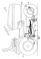
- a lawn and Garden tractor or a vehicle 10 with an attachment such as for example a mower 12, which is shown height adjustable is attached to this.
- the vehicle 10 further has front wheels 14 and rear wheels 16, which are sufficiently spaced to accommodate the mower deck 12 to become.
- the mower 12 has a housing which a vehicle frame movable by means of a usual Four-bar parallel lever lifting device (not in detail shown) on front and rear brackets 18, 20th is appropriate.
- This lifting device is designed such that a front and a rear area of the housing 22 evenly is raised, making its height relative to a frame 28 of the vehicle 10 is adjustable.
- the Brackets 18 and 20 each pair a sideways extending right and left holders 18L, 18R and 20L, 20R on.
- the front region of the housing 22 is preferably with the Frame 28, connected in a way as by the US Patent 5,025,617 is shown, the entire Disclosure is incorporated herein by reference.
- the However, the main focus of the present invention is on an attachment for connecting the rear area of the Housing 22 with the frame 28.
- Figures 2 and 3 show an attachment device for connection one or more of the brackets 20 with the lifting device and the frame 28 of the vehicle 10.
- the attachment points at least one rear lifting arm and preferably two rigid, elongated rear lifting arms 24L, 24R.
- a first one End region 26 of the lifting arm 24L or 24R is pivotable with the Frame 28 of the vehicle 10 connected.
- a central area 36 of the Lift arm 24L or 24R can be swiveled with the lifting device connected.
- the lifting arm 24L, 24R has a second forked one End area 30 on.
- the forked end portion 30 has a pair vertically spaced upper and lower fingers or tines 32, 34, which extend in the longitudinal direction.
- the upper Tine 32 is preferably substantially longer than or extends extending in the longitudinal direction beyond the lower tines 34.
- the upper and lower tines 32, 34 determined one between themselves elongated, essentially longitudinal extending, closed end space or slot 38.
- the upper prong 32 and the lower prong 34 are also so aligned that they're essentially on the same level are arranged, which is substantially vertical when the Lift arm 24L, 24R is attached.
- the upper tine 32 tapers to a blunt end area facing away from the center of the body a vertical plane so that the one end is closed Slot 38 has an open end portion that is wider than the rest of the slot 38.
- the lift arms 24L, 24R are each preferably in one piece a substantially flat steel rod.
- the lifting arms 24L, 24R may have curvatures along their length in order to matching locations of the frame 28 to be attached and in Longitudinal direction with the corresponding holders 20L, 20R on the Housing 22 to be aligned.
- the lifting arms are 24L and 24R preferably a mirror image.
- the rear brackets 20L, 20R each have a pair longitudinally spaced, upright inner and outer Guide elements 40, 42, which are fixed to the housing 22 are connected.
- Each of the guide elements 40, 42 has a Essentially straight back area and one angled front area.
- Each of the guide elements 40, 42 also includes a flared or angled upper area and an opening or recess 44 for attaching a substantially horizontal Retaining bolt 46.
- the retaining bolt is preferably around a screw that passes through the recess 44 is stuck. Alternatively, the opening 44 can be threaded be provided to the need of a mother excluded.
- the attachment according to the present invention represents a simple and effective method of coupling a Attachment, such as a mower 12, to the frame 28 of a Vehicle 10 available. Eliminated in an advantageous manner the method the need to manually or with the mower 12 Aid or equipment other than the vehicle 10 lift yourself in place and hold it there while Retaining pins are attached.
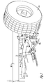
- the process includes the Steps of placing the mower 12 on the ground Lifting the lifting device and thereby lifting the lifting arms 24L, 24R, moving the vehicle 10 over the ground front and over-the-mower steering so that the forked End regions 30 of the lifting arms 24L, 24R in front of and in Longitudinally aligned with the retaining bolts 46 and the spaces between the guide elements 40, 42 of the rear brackets 20L, 20R are arranged accordingly, lowering the Lifting device around the second, forked end region 30 of the Lower the lifting arms 24L, 24R until the slot 38 between the Tines 32, 34 are at a height which is in the Essentially with the height of the retaining bolts 46 (FIG.
- the angled front areas of the guide elements 40, 42 tend to automatically cause any side misalignment correct in which the upper tine 32 in the direction of Holding bolt 46 is deflected.
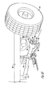
- the additional length of the top prong 32 is useful to correct any misalignment in the Correct height automatically since it tends to be on first to hit the retaining pin 46 and the lift arm 24L or 24R pushing up so that the retaining bolt 46 is finally good is moved forward into the slot 38 and through the lower Tines 34 (Fig. 3C) is supported vertically.
- the length of the Lift arms 24L, 24R can be provided such that the upper Prongs 32 touch the retaining bolt 46 when the lifting arms 24L, 24R be lowered first.
- the upper one prevents Prongs 32 the lifting arms 24L, 24R to be lowered too far to properly engage the retaining bolt 46.
- the serve angled upper regions of the guide elements 40, 42 also to automatically reduce minor side misalignments correct when the lift arms 24L, 24R engage the Move the retaining bolt 46.
- the upper front edges of the guide elements 40, 42 were removed or softened in the top and front Areas inserted so that there are no sharp edges or corners that the lift arms 24L, 24R could encounter if they approach the retaining bolt.
- the retaining bolts 46 can be in a predetermined Amount slide and become in the elongated slot 38 still supported vertically by the lower prongs 34. This Feature reduces or eliminates the need for one separate access connection.
- the operator only has to use the lifting device to lower the housing 22 to the ground, the front one To solve attachment, then the vehicle 10 to the front move until the rear lift arms 24L, 24R from the Holding bolts 46 become free.
- the present invention at least the goals set.
Landscapes
- Life Sciences & Earth Sciences (AREA)
- Environmental Sciences (AREA)
- Harvester Elements (AREA)
- Agricultural Machines (AREA)
Abstract
Description
- Fig. 1
- eine Seitenansicht eines Fahrzeugs mit einem mittels einer Anbaueinrichtung angebrachten Arbeitsgeräts,
- Fig. 2
- eine Draufsicht auf einen Rahmen des Fahrzeugs und das Anbaugerät sowie auf Hubarme und Halterungen der Anbaueinrichtung,
- Fig. 3
- eine Teilansicht des Fahrzeugs aus Fig. 1, wobei das Fahrzeug sich oberhalb des auf dem Untergrund angeordneten Anbaugeräts befindet,
- Fig. 3A
- eine Darstellung ähnlich Fig. 3, wobei der Hubarm an einen Haltebolzen angenähert ist,
- Fig. 3B
- eine Darstellung ähnlich Fig. 3, wobei der Hubarm an dem Haltebolzen angreift und
- Fig. 3C
- eine Darstellung entsprechend Fig. 3B, wobei der Haltebolzen vollständig von einem durch zwei Zinken an einem Endbereich des Hubarms gebildeten Schlitz aufgenommen wird.
Claims (9)
- Anbaueinrichtung, zur lösbaren Befestigung eines Anbaugeräts an einem Fahrzeug (10), mit einem sich zumindest im Wesentlichen horizontal erstreckenden Haltebolzen (46), welcher an dem Anbaugerät vorgesehen ist, und wenigstens einem zumindest im Wesentlichen starren Hubarm (24R, 24L) mit einem ersten Endbereich (26) zur schwenkbaren Befestigung an einem Rahmen (28) des Fahrzeugs (10), dadurch gekennzeichnet, dass der Hubarm (24R, 24L) einen zweiten dem ersten Endbereich (26) gegenüberliegenden Endbereich (30) mit wenigstens einem ersten und einem zweiten Zinken (32, 34) aufweist, welche zwischen sich einen sich zumindest im Wesentlichen in Längsrichtung des Hubarms (24R, 24L) erstreckenden, einenends geöffneten Schlitz (38) zur verschiebbaren Aufnahme des Haltebolzens (46) bestimmen.
- Anbaueinrichtung nach Anspruch 1, dadurch gekennzeichnet, dass die Anbaueinrichtung wenigstens zwei, vorzugsweise spiegelbildlich ausgebildete, Hubarme (24R, 24L) aufweist.
- Anbaueinrichtung nach einem oder mehreren der vorherigen Ansprüche, dadurch gekennzeichnet, dass sich der obere der beiden Zinken (32, 34) über den unteren Zinken (34) hinaus ragt.
- Anbaueinrichtung nach einem oder mehreren der vorherigen Ansprüche, gekennzeichnet durch ein Paar von horizontal beabstandeten zumindest im Wesentlichen aufrechten Leitelementen (40, 42), welche starr mit dem Anbaugerät verbunden sind und zwischen sich den Haltebolzen (46) aufnehmen.
- Anbaueinrichtung nach Anspruch 4, dadurch gekennzeichnet, dass die Leitelemente (40, 42) jeweilige Aussparungen (44) zur vorzugsweise ortsfesten Aufnahme des Haltebolzens (46) aufweisen, wobei der Haltebolzen (46) vorzugsweise zumindest in seinen Endbereichen mit Gewinden versehen ist, welche in Gewinde der Aussparungen (44) eingeschraubt werden können bzw. mit Muttern zur Festlegung des Haltebolzens (46) in den Leitelementen (40, 42) zusammenwirken.
- Anbaueinrichtung nach Anspruch 4 oder 5, dadurch gekennzeichnet, dass die Leitelemente (40, 42) zumindest im Wesentlichen gerade rückwärtige bzw. untere Bereiche und vordere bzw. obere Bereiche ausweisen, welche von dem rückwärtigen Bereich und dem jeweils anderen Leitelement (40, 42) weg abgewinkelte Bereiche aufweisen.
- Anbaueinrichtung nach einem oder mehreren der vorherigen Ansprüche, dadurch gekennzeichnet, dass der obere der beiden Zinken (32, 34) sich in Richtung seines äußeren Endbereichs derart verjüngt, dass der entsprechende Endbereich des Schlitzes (38) weiter ist als dessen geschlossenes Ende.
- Fahrzeug (10), insbesondere ein Fahrzeug zur Rasen-, Garten- und Grundstückspflege mit einem Anbaugerät, welches vorzugsweise in der Art eines Mähwerks (12) ausgebildet ist, welches an dem Fahrzeug (10) mittels einer Anbaueinrichtung nach einem oder mehreren der vorherigen Ansprüche angebracht werden kann.
- Verfahren zum Anbringen eines Anbaugerätes an einem Fahrzeug (10), insbesondere an einem Fahrzeug zur Rasen-, Garten- und Grundstückspflege, mittels einer Anbaueinrichtung nach einem oder mehreren der Ansprüche 1 bis 7, gekennzeichnet durch ein Anordnen des Anbaugeräts auf dem Untergrund, ein Anheben des die Zinken (32, 34) aufweisenden Endbereichs (30) des Hubarms (24R, 24L) über den Haltebolzen (46), ein Anordnen des Fahrzeugs (10) oberhalb des Anbaugeräts in der Art, dass der Endbereich (30) des Hubarms (24R, 24L) vorwärts bewegt wird und mit dem Anbaubolzen (46) fluchtet, ein Absenken des Hubarmes (24R, 24L), so dass sich der Schlitz (38) zumindest im Wesentlichen in der gleichen Höhe befindet wie der Haltebolzen (46) und ein Nach-rückwärts-Bewegen des Fahrzeugs (10) bis der Endbereich (30) des Hubarms (24R, 24L) sich mit dem Haltebolzen (46) in vertikalem Eingriff befindet.
Applications Claiming Priority (2)
| Application Number | Priority Date | Filing Date | Title |
|---|---|---|---|
| US918588 | 1997-08-19 | ||
| US09/918,588 US6470660B1 (en) | 2001-07-31 | 2001-07-31 | Mower deck rear draft quick hitch |
Publications (2)
| Publication Number | Publication Date |
|---|---|
| EP1281306A1 true EP1281306A1 (de) | 2003-02-05 |
| EP1281306B1 EP1281306B1 (de) | 2009-03-04 |
Family
ID=25440624
Family Applications (1)
| Application Number | Title | Priority Date | Filing Date |
|---|---|---|---|
| EP02017048A Expired - Lifetime EP1281306B1 (de) | 2001-07-31 | 2002-07-27 | Anbaueinrichtung, Fahrzeug und Verfahren |
Country Status (5)
| Country | Link |
|---|---|
| US (1) | US6470660B1 (de) |
| EP (1) | EP1281306B1 (de) |
| AU (1) | AU783592B2 (de) |
| CA (1) | CA2395002C (de) |
| DE (1) | DE50213327D1 (de) |
Families Citing this family (26)
| Publication number | Priority date | Publication date | Assignee | Title |
|---|---|---|---|---|
| US7028456B2 (en) * | 2003-07-14 | 2006-04-18 | Shivvers Group, Inc. | Mower with flip up mowing deck |
| US20080245045A1 (en) * | 2003-07-14 | 2008-10-09 | Shivvers Group Incorporated | Mower quick release and attachment apparatus for mowing deck |
| US7596936B2 (en) * | 2003-07-14 | 2009-10-06 | Shivvers Group, Inc. | Mower deck placed in maintenance and varying height positions |
| FR2886812A1 (fr) * | 2005-06-08 | 2006-12-15 | Sene Entpr Unipersonnelle A Re | Chassis agricole porte-outils |
| US7600363B2 (en) * | 2007-05-30 | 2009-10-13 | The Toro Company | Easily removable mower cutting deck |
| US7877972B2 (en) * | 2007-09-25 | 2011-02-01 | Deere & Company | Automatic connection mechanism for mid-mounted implement |
| US7587886B1 (en) * | 2007-12-28 | 2009-09-15 | Scag Power Equipment, Inc. | Lawnmower with cutter deck locator assembly |
| US7669394B2 (en) * | 2008-01-20 | 2010-03-02 | Exmark Mfg. Co., Inc. | Propulsion and stabilization struts for mower cutting deck |
| WO2010051409A2 (en) * | 2008-10-31 | 2010-05-06 | Briggs And Stratton Corporation | Smart tractor including communication system and engine starting system |
| US9624890B2 (en) | 2009-11-19 | 2017-04-18 | Briggs & Stratton Corporation | Push button starting system module for outdoor power equipment |
| US8171907B2 (en) | 2009-11-19 | 2012-05-08 | Briggs And Stratton Corporation | Push button starting system for outdoor power equipment |
| DE202012004215U1 (de) * | 2012-04-27 | 2012-08-09 | Kerner Maschinenbau Gmbh | Bodenbearbeitungsgerät mit Schnellkupplung zum Lösen eines Rahmenteils |
| DK2676534T3 (en) * | 2012-06-18 | 2015-06-15 | Ggp Sweden Ab | The attachment device |
| US9622406B2 (en) | 2013-12-27 | 2017-04-18 | Kubota Corporation | Mid-mount mower with power transmission coupling |
| JP6235431B2 (ja) * | 2014-08-04 | 2017-11-22 | 株式会社クボタ | ミッドマウント型草刈機 |
| JP6162600B2 (ja) * | 2013-12-27 | 2017-07-12 | 株式会社クボタ | ミッドマウント型草刈機 |
| US9693501B2 (en) | 2014-08-06 | 2017-07-04 | Shivvers Group Incorporated | Mower with scissor lift mowing height adjustment mechanism |
| US10233612B2 (en) | 2015-03-23 | 2019-03-19 | Curtis Industries, Llc | Tractor attachment and tractor attachment kit |
| US10195913B2 (en) | 2016-02-26 | 2019-02-05 | Vermeer Manufacturing Company | Two-point hitch mount systems |
| JP7145784B2 (ja) * | 2019-02-21 | 2022-10-03 | 株式会社クボタ | 作業ユニット |
| US11212952B2 (en) * | 2019-08-16 | 2022-01-04 | Deere & Company | Drive over mower deck automatic locking mechanism |
| CN110736631B (zh) * | 2019-10-28 | 2024-05-24 | 吉林大学 | 一种拖拉机液压悬挂系统在线检测自动挂接装置 |
| JP7150685B2 (ja) * | 2019-11-12 | 2022-10-11 | 株式会社クボタ | モーア |
| JP7190999B2 (ja) * | 2019-11-12 | 2022-12-16 | 株式会社クボタ | モーア |
| US12426543B2 (en) * | 2020-11-11 | 2025-09-30 | Techtronic Cordless Gp | Lawn mowers, detachable mower decks, and methods associated therewith |
| JP2026005828A (ja) * | 2024-06-27 | 2026-01-16 | 株式会社クボタ | 作業機 |
Citations (5)
| Publication number | Priority date | Publication date | Assignee | Title |
|---|---|---|---|---|
| US3948025A (en) * | 1975-04-16 | 1976-04-06 | Deere & Company | Implement draft frame |
| US5025617A (en) * | 1990-03-05 | 1991-06-25 | Deere & Company | Implement suspension mechanism |
| US5528886A (en) * | 1994-12-12 | 1996-06-25 | Moridge Manufacturing, Inc. | Hitching arrangement for a mower deck |
| US5956932A (en) * | 1998-01-22 | 1999-09-28 | Mtd Products Inc | Deck attachment mechanism and method |
| US6293077B1 (en) * | 2000-05-02 | 2001-09-25 | Mtd Products Inc | Deck attachment and lift system |
Family Cites Families (1)
| Publication number | Priority date | Publication date | Assignee | Title |
|---|---|---|---|---|
| US5970690A (en) * | 1997-10-24 | 1999-10-26 | Ransomes America Corporation | Leveling apparatus for a cutting head of a mower |
-
2001
- 2001-07-31 US US09/918,588 patent/US6470660B1/en not_active Expired - Lifetime
-
2002
- 2002-06-21 AU AU48864/02A patent/AU783592B2/en not_active Ceased
- 2002-07-25 CA CA002395002A patent/CA2395002C/en not_active Expired - Fee Related
- 2002-07-27 DE DE50213327T patent/DE50213327D1/de not_active Expired - Lifetime
- 2002-07-27 EP EP02017048A patent/EP1281306B1/de not_active Expired - Lifetime
Patent Citations (5)
| Publication number | Priority date | Publication date | Assignee | Title |
|---|---|---|---|---|
| US3948025A (en) * | 1975-04-16 | 1976-04-06 | Deere & Company | Implement draft frame |
| US5025617A (en) * | 1990-03-05 | 1991-06-25 | Deere & Company | Implement suspension mechanism |
| US5528886A (en) * | 1994-12-12 | 1996-06-25 | Moridge Manufacturing, Inc. | Hitching arrangement for a mower deck |
| US5956932A (en) * | 1998-01-22 | 1999-09-28 | Mtd Products Inc | Deck attachment mechanism and method |
| US6293077B1 (en) * | 2000-05-02 | 2001-09-25 | Mtd Products Inc | Deck attachment and lift system |
Also Published As
| Publication number | Publication date |
|---|---|
| EP1281306B1 (de) | 2009-03-04 |
| AU4886402A (en) | 2003-02-06 |
| AU783592B2 (en) | 2005-11-10 |
| DE50213327D1 (de) | 2009-04-16 |
| US6470660B1 (en) | 2002-10-29 |
| CA2395002C (en) | 2005-05-24 |
| CA2395002A1 (en) | 2003-01-31 |
Similar Documents
| Publication | Publication Date | Title |
|---|---|---|
| EP1281306B1 (de) | Anbaueinrichtung, Fahrzeug und Verfahren | |
| EP0096200B1 (de) | Fahrzeug mit einem Arbeitsgerät | |
| DE602004009338T2 (de) | Landmaschine zum schwaden von auf dem boden liegenden produkten | |
| DE19655123C2 (de) | Bearbeitungsgerät für die Tiefenlockerung von Böden | |
| DE2910164C2 (de) | Höhenverstellbare Anhängerkupplung | |
| EP0452636A1 (de) | Aufhängevorrichtung für ein Gerät an einem Fahrzeug | |
| EP0533041A1 (de) | Führungsvorrichtung für Unterlänker und landwirtschaftliches Fahrzeug | |
| DD209711A5 (de) | Bodenbearbeitungsgeraet | |
| DE1801254A1 (de) | Zugmaschine,wie Traktor od.dgl. | |
| EP2080645A1 (de) | Anhängevorrichtung | |
| DE1782910A1 (de) | Fahrzeug | |
| EP0400285A2 (de) | Vorrichtung zum Anbau eines Mähwerks | |
| DE2613718C2 (de) | An einem Schlepper anbringbare Dreipunkt-Anbauvorrichtung | |
| DE1582326A1 (de) | Maeher | |
| DE3801895A1 (de) | Vorrichtung an der frontseite eines ackerschleppers zum anheben eines zusatzgewichttraegers in eine transportstellung | |
| EP3479669B1 (de) | Landwirtschaftliche maschine | |
| DE3874253T2 (de) | Vorrichtung zum anschliessen der maehwerkbauteile an einem maehdrescher. | |
| DE2818359A1 (de) | Schmiegeegge | |
| DE1657606C3 (de) | Mähvorrichtung | |
| DE2353172C3 (de) | Selbstfahrender Mähdrescher Deere & Co, Mohne, HL (VStAi.), Niederlassung Deere & Co. European Office, 6800 Mannheim | |
| EP0105055A1 (de) | Transportwagen zur Aufnahme einer Erntebergungsvorrichtung | |
| EP0381926A2 (de) | Kupplungsvorrichtung zum Ankuppeln geschleppter Geräte bzw. Fahrzeuge, insbesondere solcher für die Landwirtschaft | |
| DE2207659A1 (de) | Aufhängevorrichtung für mit reihenmäßig arbeitenden Gerätesätzen ausgestattete landwirtschaftliche Selbstfahrmaschinen | |
| DE824123C (de) | Vorrichtung zum zeitweiligen Anheben einer an ein Zuggefaehrt angehaengten Egge | |
| DE69901285T2 (de) | Geräteanschlussmechanismus und -verfahren |
Legal Events
| Date | Code | Title | Description |
|---|---|---|---|
| PUAI | Public reference made under article 153(3) epc to a published international application that has entered the european phase |
Free format text: ORIGINAL CODE: 0009012 |
|
| AK | Designated contracting states |
Designated state(s): AT BE BG CH CY CZ DE DK EE ES FI FR GB GR IE IT LI LU MC NL PT SE SK TR |
|
| AX | Request for extension of the european patent |
Extension state: AL LT LV MK RO SI |
|
| 17P | Request for examination filed |
Effective date: 20030805 |
|
| AKX | Designation fees paid |
Designated state(s): DE FR GB IT NL |
|
| 17Q | First examination report despatched |
Effective date: 20051103 |
|
| GRAP | Despatch of communication of intention to grant a patent |
Free format text: ORIGINAL CODE: EPIDOSNIGR1 |
|
| GRAS | Grant fee paid |
Free format text: ORIGINAL CODE: EPIDOSNIGR3 |
|
| GRAA | (expected) grant |
Free format text: ORIGINAL CODE: 0009210 |
|
| AK | Designated contracting states |
Kind code of ref document: B1 Designated state(s): DE FR GB IT NL |
|
| REG | Reference to a national code |
Ref country code: GB Ref legal event code: FG4D Free format text: NOT ENGLISH |
|
| REF | Corresponds to: |
Ref document number: 50213327 Country of ref document: DE Date of ref document: 20090416 Kind code of ref document: P |
|
| PG25 | Lapsed in a contracting state [announced via postgrant information from national office to epo] |
Ref country code: NL Free format text: LAPSE BECAUSE OF FAILURE TO SUBMIT A TRANSLATION OF THE DESCRIPTION OR TO PAY THE FEE WITHIN THE PRESCRIBED TIME-LIMIT Effective date: 20090304 |
|
| NLV1 | Nl: lapsed or annulled due to failure to fulfill the requirements of art. 29p and 29m of the patents act | ||
| PLBE | No opposition filed within time limit |
Free format text: ORIGINAL CODE: 0009261 |
|
| STAA | Information on the status of an ep patent application or granted ep patent |
Free format text: STATUS: NO OPPOSITION FILED WITHIN TIME LIMIT |
|
| 26N | No opposition filed |
Effective date: 20091207 |
|
| REG | Reference to a national code |
Ref country code: FR Ref legal event code: ST Effective date: 20100331 |
|
| PG25 | Lapsed in a contracting state [announced via postgrant information from national office to epo] |
Ref country code: FR Free format text: LAPSE BECAUSE OF NON-PAYMENT OF DUE FEES Effective date: 20090731 |
|
| PG25 | Lapsed in a contracting state [announced via postgrant information from national office to epo] |
Ref country code: IT Free format text: LAPSE BECAUSE OF FAILURE TO SUBMIT A TRANSLATION OF THE DESCRIPTION OR TO PAY THE FEE WITHIN THE PRESCRIBED TIME-LIMIT Effective date: 20090304 |
|
| PGFP | Annual fee paid to national office [announced via postgrant information from national office to epo] |
Ref country code: DE Payment date: 20140619 Year of fee payment: 13 |
|
| REG | Reference to a national code |
Ref country code: DE Ref legal event code: R119 Ref document number: 50213327 Country of ref document: DE |
|
| PG25 | Lapsed in a contracting state [announced via postgrant information from national office to epo] |
Ref country code: DE Free format text: LAPSE BECAUSE OF NON-PAYMENT OF DUE FEES Effective date: 20160202 |
|
| PGFP | Annual fee paid to national office [announced via postgrant information from national office to epo] |
Ref country code: GB Payment date: 20210727 Year of fee payment: 20 |
|
| REG | Reference to a national code |
Ref country code: GB Ref legal event code: PE20 Expiry date: 20220726 |
|
| PG25 | Lapsed in a contracting state [announced via postgrant information from national office to epo] |
Ref country code: GB Free format text: LAPSE BECAUSE OF EXPIRATION OF PROTECTION Effective date: 20220726 |