EP1280609B1 - Mischdüse mit verschiebbarer drossel und sprüheinheit - Google Patents
Mischdüse mit verschiebbarer drossel und sprüheinheit Download PDFInfo
- Publication number
- EP1280609B1 EP1280609B1 EP01936015A EP01936015A EP1280609B1 EP 1280609 B1 EP1280609 B1 EP 1280609B1 EP 01936015 A EP01936015 A EP 01936015A EP 01936015 A EP01936015 A EP 01936015A EP 1280609 B1 EP1280609 B1 EP 1280609B1
- Authority
- EP
- European Patent Office
- Prior art keywords
- nozzle
- throttle body
- mixing
- water
- nozzles
- Prior art date
- Legal status (The legal status is an assumption and is not a legal conclusion. Google has not performed a legal analysis and makes no representation as to the accuracy of the status listed.)
- Expired - Lifetime
Links
Images



Classifications
-
- B—PERFORMING OPERATIONS; TRANSPORTING
- B05—SPRAYING OR ATOMISING IN GENERAL; APPLYING FLUENT MATERIALS TO SURFACES, IN GENERAL
- B05B—SPRAYING APPARATUS; ATOMISING APPARATUS; NOZZLES
- B05B7/00—Spraying apparatus for discharge of liquids or other fluent materials from two or more sources, e.g. of liquid and air, of powder and gas
- B05B7/02—Spray pistols; Apparatus for discharge
- B05B7/04—Spray pistols; Apparatus for discharge with arrangements for mixing liquids or other fluent materials before discharge
- B05B7/0416—Spray pistols; Apparatus for discharge with arrangements for mixing liquids or other fluent materials before discharge with arrangements for mixing one gas and one liquid
- B05B7/0425—Spray pistols; Apparatus for discharge with arrangements for mixing liquids or other fluent materials before discharge with arrangements for mixing one gas and one liquid without any source of compressed gas, e.g. the air being sucked by the pressurised liquid
-
- B—PERFORMING OPERATIONS; TRANSPORTING
- B01—PHYSICAL OR CHEMICAL PROCESSES OR APPARATUS IN GENERAL
- B01F—MIXING, e.g. DISSOLVING, EMULSIFYING OR DISPERSING
- B01F23/00—Mixing according to the phases to be mixed, e.g. dispersing or emulsifying
- B01F23/20—Mixing gases with liquids
- B01F23/23—Mixing gases with liquids by introducing gases into liquid media, e.g. for producing aerated liquids
- B01F23/232—Mixing gases with liquids by introducing gases into liquid media, e.g. for producing aerated liquids using flow-mixing means for introducing the gases, e.g. baffles
- B01F23/2323—Mixing gases with liquids by introducing gases into liquid media, e.g. for producing aerated liquids using flow-mixing means for introducing the gases, e.g. baffles by circulating the flow in guiding constructions or conduits
- B01F23/23231—Mixing gases with liquids by introducing gases into liquid media, e.g. for producing aerated liquids using flow-mixing means for introducing the gases, e.g. baffles by circulating the flow in guiding constructions or conduits being at least partially immersed in the liquid, e.g. in a closed circuit
-
- B—PERFORMING OPERATIONS; TRANSPORTING
- B01—PHYSICAL OR CHEMICAL PROCESSES OR APPARATUS IN GENERAL
- B01F—MIXING, e.g. DISSOLVING, EMULSIFYING OR DISPERSING
- B01F25/00—Flow mixers; Mixers for falling materials, e.g. solid particles
- B01F25/30—Injector mixers
- B01F25/31—Injector mixers in conduits or tubes through which the main component flows
- B01F25/312—Injector mixers in conduits or tubes through which the main component flows with Venturi elements; Details thereof
- B01F25/3124—Injector mixers in conduits or tubes through which the main component flows with Venturi elements; Details thereof characterised by the place of introduction of the main flow
- B01F25/31242—Injector mixers in conduits or tubes through which the main component flows with Venturi elements; Details thereof characterised by the place of introduction of the main flow the main flow being injected in the central area of the venturi, creating an aspiration in the circumferential part of the conduit
-
- B—PERFORMING OPERATIONS; TRANSPORTING
- B05—SPRAYING OR ATOMISING IN GENERAL; APPLYING FLUENT MATERIALS TO SURFACES, IN GENERAL
- B05B—SPRAYING APPARATUS; ATOMISING APPARATUS; NOZZLES
- B05B15/00—Details of spraying plant or spraying apparatus not otherwise provided for; Accessories
- B05B15/60—Arrangements for mounting, supporting or holding spraying apparatus
- B05B15/65—Mounting arrangements for fluid connection of the spraying apparatus or its outlets to flow conduits
- B05B15/658—Mounting arrangements for fluid connection of the spraying apparatus or its outlets to flow conduits the spraying apparatus or its outlet axis being perpendicular to the flow conduit
-
- B—PERFORMING OPERATIONS; TRANSPORTING
- B05—SPRAYING OR ATOMISING IN GENERAL; APPLYING FLUENT MATERIALS TO SURFACES, IN GENERAL
- B05B—SPRAYING APPARATUS; ATOMISING APPARATUS; NOZZLES
- B05B17/00—Apparatus for spraying or atomising liquids or other fluent materials, not covered by the preceding groups
- B05B17/08—Fountains
- B05B17/085—Fountains designed to produce sheets or curtains of liquid, e.g. water walls
-
- B—PERFORMING OPERATIONS; TRANSPORTING
- B05—SPRAYING OR ATOMISING IN GENERAL; APPLYING FLUENT MATERIALS TO SURFACES, IN GENERAL
- B05B—SPRAYING APPARATUS; ATOMISING APPARATUS; NOZZLES
- B05B7/00—Spraying apparatus for discharge of liquids or other fluent materials from two or more sources, e.g. of liquid and air, of powder and gas
- B05B7/02—Spray pistols; Apparatus for discharge
- B05B7/12—Spray pistols; Apparatus for discharge designed to control volume of flow, e.g. with adjustable passages
Definitions
- the invention relates to a mixing nozzle for fluid media, in particular Water-air mixtures, with a liquid nozzle that opens into the interior of an outer nozzle body, which in the Distance to the liquid nozzle is a tapering along the longitudinal axis Has zone within which a throttle body for swirling of the fluid mixture is arranged, the outlet of the Liquid nozzle as a valve seat for the longitudinal axial over a Spindle displaceable throttle body is formed.
- the invention further relates to a spray unit, which by means of a single pump with a fluid medium over a common Supply line is supplied.
- the water flows through the liquid nozzle fed by means of a pump and mixes with radial inflowing air, this water-air mixture through a throttle body is swirled so that as a result of the enrichment of the water jet with air bubbles is not transparent Fountain is created.
- the width of the water hazard can only be in segments graded from about 1 m.
- the distance of the Throttle body for the liquid nozzle outlet fixed, see above that according to the pump output or the applicable water pressure only a constant obstacle height can be generated which cannot be changed during operation.
- the height of the water fountain is namely inevitably larger in the mixing nozzles, that of the common Pump are located closest.
- the liquid supply of these mixing nozzles should be closable as possible to prevent the ingress of dirt to prevent.
- the mixing nozzle is after Claim 1 proposed.
- This is the outlet of the liquid nozzle as a valve seat for the axially axially via a spindle slidable throttle body.
- Such Mixing nozzle design is fundamentally from US 4,836,453 known as a gasoline injector.
- the mentioned throttle body of the Mixing nozzle according to claim 1 is used not only for swirling air-water mixtures, but also also because of its longitudinal axial displaceability as a closure member and adjustable throttle body. So depending on longitudinal axial position of the throttle body to the liquid nozzle outlet a more or less swirled fluid or air-water flow can be set.
- the longitudinal axial Adjustability of the throttle body also allows the fluid flow rate regulate finely.
- the throttle body is preferably by means of of an electric motor shifted axially.
- the design of the mixing nozzle is the drive spindle of the electric motor connected with a non-rotatable sleeve, which under Interposition of an elastic coupling via a connecting shaft is connected to the throttle body.
- the elastic Coupling prevents forces, especially those in act on the throttle body in the axial direction, undamped transferred to the drive spindle of the electric motor become.
- the damping generated by the clutch thus serves the protection of the electric motor and the increase in the service life of this Engine.
- the mixing nozzle has particular advantages if it has several other nozzles are combined to form a spray unit, which by means of a single pump with a fluid medium a common supply line is supplied.
- the geometrical The shape of the spray unit is basically arbitrary, however, the shape of a spray bar is preferably chosen, on which several nozzles are arranged side by side in a row are, according to a further embodiment of the invention can be individually controlled or regulated.
- the spray bar have a square tube, on or in which the Mixing nozzle are arranged in any number.
- the length of the spray bar or the number of nozzles is not limited. Every mixing nozzle can be regulated separately so that a pressure drop in the corresponding Compensated for by changing the position of the throttle body can be, so that, for example, the same have high fountains set. It is also possible that respective water-air mixture fountain height per mixing nozzle regulate so that a "water curtain" with a wavy or any curved top edge can be generated.
- Supply line on which the individual mixing nozzles are arranged are to be dimensioned large, so that locally only low flow velocities are present and thus the pressure drop across the entire pipe length or the length of the spray bar only very much is low.
- a spray bar to create artificial obstacles can create any street width covered become. There is only one central one, outside the supply line horizontal pump is needed, is accordingly their power supply much easier, but especially to make it less dangerous.
- Each mixing nozzle can be separated control, which also includes the possibility of only a part open the nozzles and close the others. So you can obstacles of any width in different locations relative to the total width of the road.
- the invention possible separate proportional control of each Nozzle creates the advantage of simulating both in terms of the location as well as the design of variable obstacle. If you use a control with the one after the other Open and close nozzles can also be movable Obstacles are simulated on which the test subjects respond to Auto test tracks should react. Such simulations are important to, for example, the movement of a to suddenly re-enact the child walking across the street.
- Fig. 1 are used for coverage the street width, for example eight spray units 11 needed, each six mixing nozzles in the case shown have.
- Each of the individual spray units 11 is a Pump 12 supplied with water.
- Fig. 1 Idealized case are three adjacent spray units 11 actuated to a water fore 13 from each individual Generate water fountains that have an obstacle width b and should represent an obstacle height h.
- the state of the Technology are regularly spray units in the form of spray bars with a width of about 1 m used, the five to six Have mixing nozzles.
- each spray unit 11 For each spray unit a separate pump 12 is used, by means of a Supply line 14 an approximately horizontal pipe 15 with water is supplied. As a result of the pressure drop, it is obvious that the mixing nozzles arranged in the middle of the spray bar generate a higher water fountain than the external ones Mixing nozzles 16.
- Each spray unit 11 thus covers a section a from, so that to cover an entire street width B (see Fig. 1) and several spray units necessary supply units are needed.
- FIG. 3 The basic structure of a mixing nozzle 16 is shown in FIG. 3 seen. That through the outlet of a liquid nozzle 17th pumped water mixes with the radially inflowing Air to an air-water mixture that passes through the throttle body 18 swirled and in the direction of arrow 19 (upwards) is ejected.
- the throttle body 18 is crowned and is at a distance from the outlet of the liquid nozzle 12.
- Bei Mixing nozzles known from the prior art are at most manual settings possible and, if provided at all, only after opening the nozzle body. It is obvious, that in the gutters 10 dirt, stones, leaves or similar contaminants can flow, some in the lines 15 and 14 can reach the pump and disrupt its operation.
- the outlet of the liquid nozzle is a valve seat for the throttle body that can be moved longitudinally axially via a spindle formed what in the following using exemplary embodiments is explained in more detail.
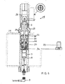
- FIG. 4 shows a mixing nozzle 20 according to the invention, of which several are integrated in a square tube 21.
- Any of these Mixing nozzles has a throttle body 1, which is adjustable axially and on the side facing the liquid nozzle 2 is conical, so that by means of the throttle body 1 the liquid nozzle 2 can be closed, the Outlet in a corresponding manner as a valve seat for the conical Throttle body part is formed.
- the longitudinal axial adjustment of the throttle body 1 is by means of the connecting shaft 3 possible with an elastic coupling 4 with a counter Twist secured sleeve 5 connected to an internal thread is.
- the sleeve 5 is on the drive spindle 6 of the electric motor 7 coupled, by their rotation depending on the direction of rotation the sleeve 5 according to the thread pitch forward or is moved back.
- the motor 7 is equipped with an encoder 8.
- the water under pressure in the interior of the square tubes 21 reaches the interior 23 via provided openings 22 the liquid nozzle to its outlet where it is sucked in Air (see arrow 24) is mixed and passed through the mixing nozzle outlet 25 is expelled.
- the flow rate and the pressure of the water-air mixture and thus the achievable jet height of the mixing nozzle 20 can be varied.
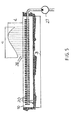
- Fig. 5 shows the already mentioned square tube 21 with shown 48 mixing nozzles 20, which are arranged equidistant from each other are.
- the square tube 21 extends as a spray bar in essentially over the entire width B of the street or Channel 10 in which the spray bar is arranged.
- the square tube 21 is supplied with water via a single pump 27. Due to the separate controllability of each individual mixing nozzle any obstacle widths c or obstacle heights d are generated, as shown in principle in FIG. 5.
- the water wall generated there from individual water jets 28, which are shown in dashed lines can be anywhere continue to be generated also for motion simulation.
- Those Mixing nozzles 20, which should not emit a water jet are by lowering the throttle body 1 on the liquid nozzle outlet 2, which is designed as a corresponding valve seat is closed.
- the mixing nozzle 29 shown in FIG. 6 is similar to the mixing nozzle 4 constructed so that the same parts with the same Reference numerals have been provided. This mixing nozzle has however the following new features:
- the bottom 30 is conical, so that water remains drain or the system can be completely drained.
- a slot 31 is provided for the Guide bush 32 and a clutch 33 with a driver 34.
- the throttle body 35 is spherical and in a closed position, i.e. shown lying on the valve seat.
- a cross-shaped is at the nozzle outlet Baffle 36 provided in connection with the spherical closure body an improved spray pattern results.
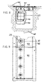
- a spray bar module 37 is shown, the one Has width B of approx. 2 m in length with eight mixing nozzles 29 according to FIG. 6, which is equidistantly spaced are arranged to each other.
- the existing pressure relief valve is with reference numeral 38 and the control electronics Numeral 39 numbered.
- An adjustable suspension 40 of the bar can also be seen 37 provided with which an adaptation to the gradient of the Road can be brought about.
- a frame 42 serves this purpose, on which the spray bar 37 is suspended.
- the spray bar 37 is on the outside with a seal 43 which on a Flange 44 is attached, provided and in a recess of a concrete structure 45 let in at the top by a cover plate 41 is shielded.
- the cover plate 41 the Area 43 according to FIG. 9 has been removed, covers the recess in the concrete plant 45 down to a narrow slit which the mixing nozzles 29 (or 20) according to the invention are located.
- the advantage of the mixing nozzle or spray unit according to the invention becomes immediately clear by comparison with FIG. 1: While it by means of mixing nozzles known from the prior art 16 or spray units 11 is only possible, each graded The artificial can create obstacle widths Obstacle widths with the spray unit according to FIG. 5 or 7 to 9 can be adjusted more finely. Since also during the fountain-like Operation an individual regulation or control of the individual mixing nozzles is possible, the obstacles when water pressure is present in the desired manner both in the height as well as the width as well as in terms of location and the time course can be varied.
- Such embodiments are also of the present invention recorded, in which no linear spray bar, but different shaped spray units can be used. These can be in one Level, for example in an S or Z shape or in space as a spiral be trained, which is suitable for fountains or the like Water feature using individually adjustable fountains only with a single pump.
- the spray bar or the nozzles can be set so that they only spray about 10 to 20 cm high, so that the in Spray bars embedded in the concrete plant can also be used in order to be able to irrigate the roadway, for example for testing aquaplaning behavior.
- a complete system can consist of several arranged side by side Spray bars 37 are assembled in a modular manner, for example in variations to a multiple of a 2 m tall Width, i.e. 4 m, 6 m, 8 m etc. road sections be provided with a spray bar arrangement.
- the single ones Spray bars can be used, for example, with a flange connect an overall bar.
Landscapes
- Chemical & Material Sciences (AREA)
- Chemical Kinetics & Catalysis (AREA)
- Nozzles (AREA)
- Special Spraying Apparatus (AREA)
Description
- Fig. 1
- ein herkömmliches System aus mehreren nebenein ander angeordneten Sprüheinheiten,
- Fig. 2
- eine Sprüheinheit mit einer Versorgungspumpe (Stand der Technik),
- Fig. 3
- einen Querschnitt durch eine Mischdüse,
- Fig. 4
- einen Querschnitt durch eine erfindungsgemäße Mischdüse,
- Fig. 5
- eine Sprüheinheit mit mehreren Mischdüsen gemäß der vorliegenden Erfindung,
- Fig. 6
- einen Querschnitt durch eine weitere erfindungsgemäße Mischdüse,
- Fig. 7
- eine weitere Sprüheinheit in einer Längsschnittansicht,
- Fig. 8
- eine Querschnittsansicht der Sprüheinheit nach Fig. 7 und
- Fig. 9
- eine Teil-Draufsicht auf die Sprüheinheit nach Fig. 7 bzw. 8.
Claims (6)
- Mischdüse für fluide Medien, insbesondere Wasser-Luft-Gemische, mit einer Flüssigkeitsdüse (2), die in den Innenraum eines äußeren Düsenkörpers (29) mündet, der im Abstand zur Flüssigkeitsdüse (2) eine sich längsaxial verjüngende Zone (26) aufweist, innerhalb der ein Drosselkörper (1) zur Verwirbelung des fluiden Gemisches angeordnet ist, wobei der Auslaß der Flüssigkeitsdüse (2) als Ventilsitz für den längsaxial über eine Spindel (6, 5) verschiebbaren Drosselkörper (1, 35) ausgebildet ist, dadurch gekennzeichnet, daß der Drosselkörper (1, 35) mittels eines Elektromotors (7) längsaxial verschiebbar ist und daß die Antriebsspindel (6) des Elektromotors (7) mit einer drehgesicherten Hülse (5) verbunden ist, die unter Zwischenschaltung einer elastischen Kupplung (4) über eine Verbindungswelle (3) mit dem Drosselkörper (1) verbunden ist.
- Mischdüse nach Anspruch 1, dadurch gekennzeichnet, daß der Elektromotor (7) mit einem Meßgeber (8) zur Lagebestimmung des Drosselkörpers (1) verbunden ist.
- Sprüheinheit, die mittels einer einzigen Pumpe (27) mit einem fluiden Medium über eine gemeinsame Zufuhrleitung (21) versorgt wird, gekennzeichnet durch mehrere Mischdüsen (20) nach einem der Ansprüche 1 oder 2.
- Sprüheinheit nach Anspruch 3, dadurch gekennzeichnet, daß diese als Sprühbalken (21, 37) ausgebildet ist.
- Sprüheinheit nach Anspruch 3 oder 4, dadurch gekennzeichnet, daß die Mischdüsen (20, 29) getrennt steuer- oder regelbar sind.
- Sprüheinheit nach einem der Ansprüche 4 oder 7, dadurch gekennzeichnet, daß der Sprühbalken ein Vierkantrohr (21) aufweist, in dem mehrere Mischdüsen (20, 29) in einer Reihe hintereinander montiert sind.
Applications Claiming Priority (3)
| Application Number | Priority Date | Filing Date | Title |
|---|---|---|---|
| DE10022073A DE10022073A1 (de) | 2000-05-06 | 2000-05-06 | Mischdüse und Sprüheinheit |
| DE10022073 | 2000-05-06 | ||
| PCT/DE2001/001642 WO2001085354A1 (de) | 2000-05-06 | 2001-04-28 | Mischdüse mit verschiebbarer drossel und sprüheinheit |
Publications (2)
| Publication Number | Publication Date |
|---|---|
| EP1280609A1 EP1280609A1 (de) | 2003-02-05 |
| EP1280609B1 true EP1280609B1 (de) | 2004-01-02 |
Family
ID=7640988
Family Applications (1)
| Application Number | Title | Priority Date | Filing Date |
|---|---|---|---|
| EP01936015A Expired - Lifetime EP1280609B1 (de) | 2000-05-06 | 2001-04-28 | Mischdüse mit verschiebbarer drossel und sprüheinheit |
Country Status (4)
| Country | Link |
|---|---|
| EP (1) | EP1280609B1 (de) |
| AT (1) | ATE257039T1 (de) |
| DE (2) | DE10022073A1 (de) |
| WO (1) | WO2001085354A1 (de) |
Families Citing this family (1)
| Publication number | Priority date | Publication date | Assignee | Title |
|---|---|---|---|---|
| DE10247763A1 (de) | 2002-10-14 | 2004-06-03 | Robert Bosch Gmbh | Zerstäuberdüse |
Family Cites Families (6)
| Publication number | Priority date | Publication date | Assignee | Title |
|---|---|---|---|---|
| US1643967A (en) * | 1923-04-12 | 1927-10-04 | Sta Kleen Burner Company | Low-pressure oil burner |
| BE439980A (de) * | 1938-05-28 | |||
| US2259011A (en) * | 1939-05-24 | 1941-10-14 | William F Doyle | Atomizer for liquid fuels |
| US4836453A (en) * | 1988-02-22 | 1989-06-06 | Outboard Marine Corporation | Fuel injector with continuous air flow |
| DE4440666A1 (de) * | 1994-11-04 | 1996-05-09 | Bbj Servis Ggmbh Fuer Jugendhi | Zerstäubungsvorrichtung |
| DE29700463U1 (de) * | 1997-01-04 | 1997-05-22 | Gustav Schlick GmbH & Co, 96253 Untersiemau | Zerstäuber-Düsen-Anordnung |
-
2000
- 2000-05-06 DE DE10022073A patent/DE10022073A1/de not_active Withdrawn
-
2001
- 2001-04-28 WO PCT/DE2001/001642 patent/WO2001085354A1/de not_active Ceased
- 2001-04-28 EP EP01936015A patent/EP1280609B1/de not_active Expired - Lifetime
- 2001-04-28 DE DE50101270T patent/DE50101270D1/de not_active Expired - Lifetime
- 2001-04-28 AT AT01936015T patent/ATE257039T1/de not_active IP Right Cessation
Also Published As
| Publication number | Publication date |
|---|---|
| WO2001085354A1 (de) | 2001-11-15 |
| DE50101270D1 (de) | 2004-02-05 |
| EP1280609A1 (de) | 2003-02-05 |
| ATE257039T1 (de) | 2004-01-15 |
| DE10022073A1 (de) | 2001-11-08 |
Similar Documents
| Publication | Publication Date | Title |
|---|---|---|
| DE69831220T2 (de) | Fahrbare sprühvorrichtung und sprühverfahren | |
| DE10246334A1 (de) | Sanitäres Einbauteil | |
| DE102016102756A1 (de) | Regelzylinder für eine Regelarmatur und Regelarmatur mit einem derartigen Regelzylinder | |
| DE3024421A1 (de) | Bewaesserungsvorrichtung und verfahren zur bewaesserung | |
| DE2632313B2 (de) | Anlage zum Üben der Reaktion und des Fahrverhaltens eines Kraftfahrzeuglenkers in einer Notfallsituation | |
| DE102006044806A1 (de) | Vorrichtung zur Erzeugung gerader stehender Wellen | |
| DE69107565T2 (de) | Luftdüse für Klimaanlage in Kraftfahrzeugen. | |
| DE102017110501B4 (de) | Vorrichtung zur Bewässerung von Fahrbahnen | |
| EP1122050A2 (de) | Vorrichtung zum kalibrierenden Abkühlen eines stranggepressten Kunststoffprofils | |
| DE102011114945A1 (de) | Brausekopf | |
| EP0505977A1 (de) | Schaltungsanordnung zur Geschwindigkeitssteuerung von hydraulischen Antrieben, vorzugsweise hydraulischen Arbeitszylindern | |
| DE4405961C2 (de) | Vorrichtung zum Begasen einer Flüssigkeit | |
| AT520057B1 (de) | Vorrichtung zur Bewässerung von Fahrbahnen | |
| EP1280609A1 (de) | Mischdüse mit verschiebbarer drossel und sprüheinheit | |
| DE20008181U1 (de) | Mischdüse und Sprüheinheit | |
| DE3710830C2 (de) | ||
| DE10314057B3 (de) | Schnorchelvorrichtung für ein U-Boot | |
| DE1963720A1 (de) | Tiefgruendungselement,insbesondere durch Ruetteln in den Boden eintreibbarer Ortpfahl mit Schuh | |
| EP0011881A1 (de) | Gliederautobus | |
| EP0638372B1 (de) | Gerät zum Injizieren von Gasen in Böden | |
| DE10256199B4 (de) | Vorrichtung und Verfahren zur Veränderung der Streckenführung einer Fahrzeugrennstrecke | |
| DE102004062008A1 (de) | Kraftstofffilter mit Auslassöffnungen, die vorzugsweise mit einem hydroerosiven Verfahren bearbeitet sind | |
| DE102015013142A1 (de) | Vorrichtung zum Reinigen von Fahrzeugreifen | |
| DE1501372A1 (de) | Kuehlsystem,insbesondere fuer Walzwerke | |
| EP1099803B1 (de) | Versickerungsvorrichtung |
Legal Events
| Date | Code | Title | Description |
|---|---|---|---|
| PUAI | Public reference made under article 153(3) epc to a published international application that has entered the european phase |
Free format text: ORIGINAL CODE: 0009012 |
|
| 17P | Request for examination filed |
Effective date: 20020828 |
|
| AK | Designated contracting states |
Designated state(s): AT BE CH CY DE DK ES FI FR GB GR IE IT LI LU MC NL PT SE TR |
|
| GRAP | Despatch of communication of intention to grant a patent |
Free format text: ORIGINAL CODE: EPIDOSNIGR1 |
|
| GRAS | Grant fee paid |
Free format text: ORIGINAL CODE: EPIDOSNIGR3 |
|
| GRAA | (expected) grant |
Free format text: ORIGINAL CODE: 0009210 |
|
| AK | Designated contracting states |
Kind code of ref document: B1 Designated state(s): AT BE CH CY DE DK ES FI FR GB GR IE IT LI LU MC NL PT SE TR |
|
| PG25 | Lapsed in a contracting state [announced via postgrant information from national office to epo] |
Ref country code: IT Free format text: LAPSE BECAUSE OF FAILURE TO SUBMIT A TRANSLATION OF THE DESCRIPTION OR TO PAY THE FEE WITHIN THE PRESCRIBED TIME-LIMIT;WARNING: LAPSES OF ITALIAN PATENTS WITH EFFECTIVE DATE BEFORE 2007 MAY HAVE OCCURRED AT ANY TIME BEFORE 2007. THE CORRECT EFFECTIVE DATE MAY BE DIFFERENT FROM THE ONE RECORDED. Effective date: 20040102 Ref country code: IE Free format text: LAPSE BECAUSE OF FAILURE TO SUBMIT A TRANSLATION OF THE DESCRIPTION OR TO PAY THE FEE WITHIN THE PRESCRIBED TIME-LIMIT Effective date: 20040102 Ref country code: NL Free format text: LAPSE BECAUSE OF FAILURE TO SUBMIT A TRANSLATION OF THE DESCRIPTION OR TO PAY THE FEE WITHIN THE PRESCRIBED TIME-LIMIT Effective date: 20040102 Ref country code: TR Free format text: LAPSE BECAUSE OF FAILURE TO SUBMIT A TRANSLATION OF THE DESCRIPTION OR TO PAY THE FEE WITHIN THE PRESCRIBED TIME-LIMIT Effective date: 20040102 Ref country code: FR Free format text: LAPSE BECAUSE OF FAILURE TO SUBMIT A TRANSLATION OF THE DESCRIPTION OR TO PAY THE FEE WITHIN THE PRESCRIBED TIME-LIMIT Effective date: 20040102 Ref country code: CY Free format text: LAPSE BECAUSE OF FAILURE TO SUBMIT A TRANSLATION OF THE DESCRIPTION OR TO PAY THE FEE WITHIN THE PRESCRIBED TIME-LIMIT Effective date: 20040102 Ref country code: FI Free format text: LAPSE BECAUSE OF FAILURE TO SUBMIT A TRANSLATION OF THE DESCRIPTION OR TO PAY THE FEE WITHIN THE PRESCRIBED TIME-LIMIT Effective date: 20040102 Ref country code: GB Free format text: LAPSE BECAUSE OF FAILURE TO SUBMIT A TRANSLATION OF THE DESCRIPTION OR TO PAY THE FEE WITHIN THE PRESCRIBED TIME-LIMIT Effective date: 20040102 |
|
| REG | Reference to a national code |
Ref country code: GB Ref legal event code: FG4D Free format text: NOT ENGLISH |
|
| REG | Reference to a national code |
Ref country code: CH Ref legal event code: EP |
|
| REG | Reference to a national code |
Ref country code: IE Ref legal event code: FG4D Free format text: GERMAN |
|
| REF | Corresponds to: |
Ref document number: 50101270 Country of ref document: DE Date of ref document: 20040205 Kind code of ref document: P |
|
| PG25 | Lapsed in a contracting state [announced via postgrant information from national office to epo] |
Ref country code: DK Free format text: LAPSE BECAUSE OF FAILURE TO SUBMIT A TRANSLATION OF THE DESCRIPTION OR TO PAY THE FEE WITHIN THE PRESCRIBED TIME-LIMIT Effective date: 20040402 Ref country code: SE Free format text: LAPSE BECAUSE OF FAILURE TO SUBMIT A TRANSLATION OF THE DESCRIPTION OR TO PAY THE FEE WITHIN THE PRESCRIBED TIME-LIMIT Effective date: 20040402 Ref country code: GR Free format text: LAPSE BECAUSE OF FAILURE TO SUBMIT A TRANSLATION OF THE DESCRIPTION OR TO PAY THE FEE WITHIN THE PRESCRIBED TIME-LIMIT Effective date: 20040402 |
|
| PG25 | Lapsed in a contracting state [announced via postgrant information from national office to epo] |
Ref country code: ES Free format text: LAPSE BECAUSE OF FAILURE TO SUBMIT A TRANSLATION OF THE DESCRIPTION OR TO PAY THE FEE WITHIN THE PRESCRIBED TIME-LIMIT Effective date: 20040413 |
|
| PG25 | Lapsed in a contracting state [announced via postgrant information from national office to epo] |
Ref country code: AT Free format text: LAPSE BECAUSE OF NON-PAYMENT OF DUE FEES Effective date: 20040428 Ref country code: LU Free format text: LAPSE BECAUSE OF NON-PAYMENT OF DUE FEES Effective date: 20040428 |
|
| PG25 | Lapsed in a contracting state [announced via postgrant information from national office to epo] |
Ref country code: BE Free format text: LAPSE BECAUSE OF NON-PAYMENT OF DUE FEES Effective date: 20040430 Ref country code: MC Free format text: LAPSE BECAUSE OF NON-PAYMENT OF DUE FEES Effective date: 20040430 |
|
| NLV1 | Nl: lapsed or annulled due to failure to fulfill the requirements of art. 29p and 29m of the patents act | ||
| GBV | Gb: ep patent (uk) treated as always having been void in accordance with gb section 77(7)/1977 [no translation filed] |
Effective date: 20040102 |
|
| REG | Reference to a national code |
Ref country code: IE Ref legal event code: FD4D |
|
| BERE | Be: lapsed |
Owner name: EVERTZ HYDROTECHNIK G.M.B.H. & CO. KG Effective date: 20040430 |
|
| PLBE | No opposition filed within time limit |
Free format text: ORIGINAL CODE: 0009261 |
|
| STAA | Information on the status of an ep patent application or granted ep patent |
Free format text: STATUS: NO OPPOSITION FILED WITHIN TIME LIMIT |
|
| 26N | No opposition filed |
Effective date: 20041005 |
|
| EN | Fr: translation not filed | ||
| PG25 | Lapsed in a contracting state [announced via postgrant information from national office to epo] |
Ref country code: CH Free format text: LAPSE BECAUSE OF NON-PAYMENT OF DUE FEES Effective date: 20050430 Ref country code: LI Free format text: LAPSE BECAUSE OF NON-PAYMENT OF DUE FEES Effective date: 20050430 |
|
| REG | Reference to a national code |
Ref country code: CH Ref legal event code: PL |
|
| PG25 | Lapsed in a contracting state [announced via postgrant information from national office to epo] |
Ref country code: PT Free format text: LAPSE BECAUSE OF NON-PAYMENT OF DUE FEES Effective date: 20040602 |
|
| PGFP | Annual fee paid to national office [announced via postgrant information from national office to epo] |
Ref country code: DE Payment date: 20150203 Year of fee payment: 15 |
|
| REG | Reference to a national code |
Ref country code: DE Ref legal event code: R119 Ref document number: 50101270 Country of ref document: DE |
|
| PG25 | Lapsed in a contracting state [announced via postgrant information from national office to epo] |
Ref country code: DE Free format text: LAPSE BECAUSE OF NON-PAYMENT OF DUE FEES Effective date: 20161101 |