EP1278481B1 - Endoprothese intravasculaire - Google Patents
Endoprothese intravasculaire Download PDFInfo
- Publication number
- EP1278481B1 EP1278481B1 EP01926978A EP01926978A EP1278481B1 EP 1278481 B1 EP1278481 B1 EP 1278481B1 EP 01926978 A EP01926978 A EP 01926978A EP 01926978 A EP01926978 A EP 01926978A EP 1278481 B1 EP1278481 B1 EP 1278481B1
- Authority
- EP
- European Patent Office
- Prior art keywords
- stent
- cylindrical
- cylindrical ring
- undulating
- struts
- Prior art date
- Legal status (The legal status is an assumption and is not a legal conclusion. Google has not performed a legal analysis and makes no representation as to the accuracy of the status listed.)
- Revoked
Links
Images


Classifications
-
- A—HUMAN NECESSITIES
- A61—MEDICAL OR VETERINARY SCIENCE; HYGIENE
- A61F—FILTERS IMPLANTABLE INTO BLOOD VESSELS; PROSTHESES; DEVICES PROVIDING PATENCY TO, OR PREVENTING COLLAPSING OF, TUBULAR STRUCTURES OF THE BODY, e.g. STENTS; ORTHOPAEDIC, NURSING OR CONTRACEPTIVE DEVICES; FOMENTATION; TREATMENT OR PROTECTION OF EYES OR EARS; BANDAGES, DRESSINGS OR ABSORBENT PADS; FIRST-AID KITS
- A61F2/00—Filters implantable into blood vessels; Prostheses, i.e. artificial substitutes or replacements for parts of the body; Appliances for connecting them with the body; Devices providing patency to, or preventing collapsing of, tubular structures of the body, e.g. stents
- A61F2/82—Devices providing patency to, or preventing collapsing of, tubular structures of the body, e.g. stents
- A61F2/86—Stents in a form characterised by the wire-like elements; Stents in the form characterised by a net-like or mesh-like structure
- A61F2/90—Stents in a form characterised by the wire-like elements; Stents in the form characterised by a net-like or mesh-like structure characterised by a net-like or mesh-like structure
- A61F2/91—Stents in a form characterised by the wire-like elements; Stents in the form characterised by a net-like or mesh-like structure characterised by a net-like or mesh-like structure made from perforated sheet material or tubes, e.g. perforated by laser cuts or etched holes
- A61F2/915—Stents in a form characterised by the wire-like elements; Stents in the form characterised by a net-like or mesh-like structure characterised by a net-like or mesh-like structure made from perforated sheet material or tubes, e.g. perforated by laser cuts or etched holes with bands having a meander structure, adjacent bands being connected to each other
-
- A—HUMAN NECESSITIES
- A61—MEDICAL OR VETERINARY SCIENCE; HYGIENE
- A61F—FILTERS IMPLANTABLE INTO BLOOD VESSELS; PROSTHESES; DEVICES PROVIDING PATENCY TO, OR PREVENTING COLLAPSING OF, TUBULAR STRUCTURES OF THE BODY, e.g. STENTS; ORTHOPAEDIC, NURSING OR CONTRACEPTIVE DEVICES; FOMENTATION; TREATMENT OR PROTECTION OF EYES OR EARS; BANDAGES, DRESSINGS OR ABSORBENT PADS; FIRST-AID KITS
- A61F2/00—Filters implantable into blood vessels; Prostheses, i.e. artificial substitutes or replacements for parts of the body; Appliances for connecting them with the body; Devices providing patency to, or preventing collapsing of, tubular structures of the body, e.g. stents
- A61F2/82—Devices providing patency to, or preventing collapsing of, tubular structures of the body, e.g. stents
- A61F2/844—Devices providing patency to, or preventing collapsing of, tubular structures of the body, e.g. stents folded prior to deployment
-
- A—HUMAN NECESSITIES
- A61—MEDICAL OR VETERINARY SCIENCE; HYGIENE
- A61F—FILTERS IMPLANTABLE INTO BLOOD VESSELS; PROSTHESES; DEVICES PROVIDING PATENCY TO, OR PREVENTING COLLAPSING OF, TUBULAR STRUCTURES OF THE BODY, e.g. STENTS; ORTHOPAEDIC, NURSING OR CONTRACEPTIVE DEVICES; FOMENTATION; TREATMENT OR PROTECTION OF EYES OR EARS; BANDAGES, DRESSINGS OR ABSORBENT PADS; FIRST-AID KITS
- A61F2/00—Filters implantable into blood vessels; Prostheses, i.e. artificial substitutes or replacements for parts of the body; Appliances for connecting them with the body; Devices providing patency to, or preventing collapsing of, tubular structures of the body, e.g. stents
- A61F2/82—Devices providing patency to, or preventing collapsing of, tubular structures of the body, e.g. stents
- A61F2/86—Stents in a form characterised by the wire-like elements; Stents in the form characterised by a net-like or mesh-like structure
- A61F2/90—Stents in a form characterised by the wire-like elements; Stents in the form characterised by a net-like or mesh-like structure characterised by a net-like or mesh-like structure
- A61F2/91—Stents in a form characterised by the wire-like elements; Stents in the form characterised by a net-like or mesh-like structure characterised by a net-like or mesh-like structure made from perforated sheet material or tubes, e.g. perforated by laser cuts or etched holes
- A61F2/915—Stents in a form characterised by the wire-like elements; Stents in the form characterised by a net-like or mesh-like structure characterised by a net-like or mesh-like structure made from perforated sheet material or tubes, e.g. perforated by laser cuts or etched holes with bands having a meander structure, adjacent bands being connected to each other
- A61F2002/91516—Stents in a form characterised by the wire-like elements; Stents in the form characterised by a net-like or mesh-like structure characterised by a net-like or mesh-like structure made from perforated sheet material or tubes, e.g. perforated by laser cuts or etched holes with bands having a meander structure, adjacent bands being connected to each other the meander having a change in frequency along the band
-
- A—HUMAN NECESSITIES
- A61—MEDICAL OR VETERINARY SCIENCE; HYGIENE
- A61F—FILTERS IMPLANTABLE INTO BLOOD VESSELS; PROSTHESES; DEVICES PROVIDING PATENCY TO, OR PREVENTING COLLAPSING OF, TUBULAR STRUCTURES OF THE BODY, e.g. STENTS; ORTHOPAEDIC, NURSING OR CONTRACEPTIVE DEVICES; FOMENTATION; TREATMENT OR PROTECTION OF EYES OR EARS; BANDAGES, DRESSINGS OR ABSORBENT PADS; FIRST-AID KITS
- A61F2/00—Filters implantable into blood vessels; Prostheses, i.e. artificial substitutes or replacements for parts of the body; Appliances for connecting them with the body; Devices providing patency to, or preventing collapsing of, tubular structures of the body, e.g. stents
- A61F2/82—Devices providing patency to, or preventing collapsing of, tubular structures of the body, e.g. stents
- A61F2/86—Stents in a form characterised by the wire-like elements; Stents in the form characterised by a net-like or mesh-like structure
- A61F2/90—Stents in a form characterised by the wire-like elements; Stents in the form characterised by a net-like or mesh-like structure characterised by a net-like or mesh-like structure
- A61F2/91—Stents in a form characterised by the wire-like elements; Stents in the form characterised by a net-like or mesh-like structure characterised by a net-like or mesh-like structure made from perforated sheet material or tubes, e.g. perforated by laser cuts or etched holes
- A61F2/915—Stents in a form characterised by the wire-like elements; Stents in the form characterised by a net-like or mesh-like structure characterised by a net-like or mesh-like structure made from perforated sheet material or tubes, e.g. perforated by laser cuts or etched holes with bands having a meander structure, adjacent bands being connected to each other
- A61F2002/91533—Stents in a form characterised by the wire-like elements; Stents in the form characterised by a net-like or mesh-like structure characterised by a net-like or mesh-like structure made from perforated sheet material or tubes, e.g. perforated by laser cuts or etched holes with bands having a meander structure, adjacent bands being connected to each other characterised by the phase between adjacent bands
-
- A—HUMAN NECESSITIES
- A61—MEDICAL OR VETERINARY SCIENCE; HYGIENE
- A61F—FILTERS IMPLANTABLE INTO BLOOD VESSELS; PROSTHESES; DEVICES PROVIDING PATENCY TO, OR PREVENTING COLLAPSING OF, TUBULAR STRUCTURES OF THE BODY, e.g. STENTS; ORTHOPAEDIC, NURSING OR CONTRACEPTIVE DEVICES; FOMENTATION; TREATMENT OR PROTECTION OF EYES OR EARS; BANDAGES, DRESSINGS OR ABSORBENT PADS; FIRST-AID KITS
- A61F2/00—Filters implantable into blood vessels; Prostheses, i.e. artificial substitutes or replacements for parts of the body; Appliances for connecting them with the body; Devices providing patency to, or preventing collapsing of, tubular structures of the body, e.g. stents
- A61F2/82—Devices providing patency to, or preventing collapsing of, tubular structures of the body, e.g. stents
- A61F2/86—Stents in a form characterised by the wire-like elements; Stents in the form characterised by a net-like or mesh-like structure
- A61F2/90—Stents in a form characterised by the wire-like elements; Stents in the form characterised by a net-like or mesh-like structure characterised by a net-like or mesh-like structure
- A61F2/91—Stents in a form characterised by the wire-like elements; Stents in the form characterised by a net-like or mesh-like structure characterised by a net-like or mesh-like structure made from perforated sheet material or tubes, e.g. perforated by laser cuts or etched holes
- A61F2/915—Stents in a form characterised by the wire-like elements; Stents in the form characterised by a net-like or mesh-like structure characterised by a net-like or mesh-like structure made from perforated sheet material or tubes, e.g. perforated by laser cuts or etched holes with bands having a meander structure, adjacent bands being connected to each other
- A61F2002/9155—Adjacent bands being connected to each other
- A61F2002/91575—Adjacent bands being connected to each other connected peak to trough
-
- A—HUMAN NECESSITIES
- A61—MEDICAL OR VETERINARY SCIENCE; HYGIENE
- A61F—FILTERS IMPLANTABLE INTO BLOOD VESSELS; PROSTHESES; DEVICES PROVIDING PATENCY TO, OR PREVENTING COLLAPSING OF, TUBULAR STRUCTURES OF THE BODY, e.g. STENTS; ORTHOPAEDIC, NURSING OR CONTRACEPTIVE DEVICES; FOMENTATION; TREATMENT OR PROTECTION OF EYES OR EARS; BANDAGES, DRESSINGS OR ABSORBENT PADS; FIRST-AID KITS
- A61F2/00—Filters implantable into blood vessels; Prostheses, i.e. artificial substitutes or replacements for parts of the body; Appliances for connecting them with the body; Devices providing patency to, or preventing collapsing of, tubular structures of the body, e.g. stents
- A61F2/82—Devices providing patency to, or preventing collapsing of, tubular structures of the body, e.g. stents
- A61F2/86—Stents in a form characterised by the wire-like elements; Stents in the form characterised by a net-like or mesh-like structure
- A61F2/90—Stents in a form characterised by the wire-like elements; Stents in the form characterised by a net-like or mesh-like structure characterised by a net-like or mesh-like structure
- A61F2/91—Stents in a form characterised by the wire-like elements; Stents in the form characterised by a net-like or mesh-like structure characterised by a net-like or mesh-like structure made from perforated sheet material or tubes, e.g. perforated by laser cuts or etched holes
- A61F2/915—Stents in a form characterised by the wire-like elements; Stents in the form characterised by a net-like or mesh-like structure characterised by a net-like or mesh-like structure made from perforated sheet material or tubes, e.g. perforated by laser cuts or etched holes with bands having a meander structure, adjacent bands being connected to each other
- A61F2002/9155—Adjacent bands being connected to each other
- A61F2002/91583—Adjacent bands being connected to each other by a bridge, whereby at least one of its ends is connected along the length of a strut between two consecutive apices within a band
-
- A—HUMAN NECESSITIES
- A61—MEDICAL OR VETERINARY SCIENCE; HYGIENE
- A61F—FILTERS IMPLANTABLE INTO BLOOD VESSELS; PROSTHESES; DEVICES PROVIDING PATENCY TO, OR PREVENTING COLLAPSING OF, TUBULAR STRUCTURES OF THE BODY, e.g. STENTS; ORTHOPAEDIC, NURSING OR CONTRACEPTIVE DEVICES; FOMENTATION; TREATMENT OR PROTECTION OF EYES OR EARS; BANDAGES, DRESSINGS OR ABSORBENT PADS; FIRST-AID KITS
- A61F2210/00—Particular material properties of prostheses classified in groups A61F2/00 - A61F2/26 or A61F2/82 or A61F9/00 or A61F11/00 or subgroups thereof
- A61F2210/0014—Particular material properties of prostheses classified in groups A61F2/00 - A61F2/26 or A61F2/82 or A61F9/00 or A61F11/00 or subgroups thereof using shape memory or superelastic materials, e.g. nitinol
-
- A—HUMAN NECESSITIES
- A61—MEDICAL OR VETERINARY SCIENCE; HYGIENE
- A61F—FILTERS IMPLANTABLE INTO BLOOD VESSELS; PROSTHESES; DEVICES PROVIDING PATENCY TO, OR PREVENTING COLLAPSING OF, TUBULAR STRUCTURES OF THE BODY, e.g. STENTS; ORTHOPAEDIC, NURSING OR CONTRACEPTIVE DEVICES; FOMENTATION; TREATMENT OR PROTECTION OF EYES OR EARS; BANDAGES, DRESSINGS OR ABSORBENT PADS; FIRST-AID KITS
- A61F2230/00—Geometry of prostheses classified in groups A61F2/00 - A61F2/26 or A61F2/82 or A61F9/00 or A61F11/00 or subgroups thereof
- A61F2230/0002—Two-dimensional shapes, e.g. cross-sections
- A61F2230/0004—Rounded shapes, e.g. with rounded corners
- A61F2230/0013—Horseshoe-shaped, e.g. crescent-shaped, C-shaped, U-shaped
-
- A—HUMAN NECESSITIES
- A61—MEDICAL OR VETERINARY SCIENCE; HYGIENE
- A61F—FILTERS IMPLANTABLE INTO BLOOD VESSELS; PROSTHESES; DEVICES PROVIDING PATENCY TO, OR PREVENTING COLLAPSING OF, TUBULAR STRUCTURES OF THE BODY, e.g. STENTS; ORTHOPAEDIC, NURSING OR CONTRACEPTIVE DEVICES; FOMENTATION; TREATMENT OR PROTECTION OF EYES OR EARS; BANDAGES, DRESSINGS OR ABSORBENT PADS; FIRST-AID KITS
- A61F2230/00—Geometry of prostheses classified in groups A61F2/00 - A61F2/26 or A61F2/82 or A61F9/00 or A61F11/00 or subgroups thereof
- A61F2230/0002—Two-dimensional shapes, e.g. cross-sections
- A61F2230/0028—Shapes in the form of latin or greek characters
- A61F2230/0054—V-shaped
-
- A—HUMAN NECESSITIES
- A61—MEDICAL OR VETERINARY SCIENCE; HYGIENE
- A61F—FILTERS IMPLANTABLE INTO BLOOD VESSELS; PROSTHESES; DEVICES PROVIDING PATENCY TO, OR PREVENTING COLLAPSING OF, TUBULAR STRUCTURES OF THE BODY, e.g. STENTS; ORTHOPAEDIC, NURSING OR CONTRACEPTIVE DEVICES; FOMENTATION; TREATMENT OR PROTECTION OF EYES OR EARS; BANDAGES, DRESSINGS OR ABSORBENT PADS; FIRST-AID KITS
- A61F2250/00—Special features of prostheses classified in groups A61F2/00 - A61F2/26 or A61F2/82 or A61F9/00 or A61F11/00 or subgroups thereof
- A61F2250/0014—Special features of prostheses classified in groups A61F2/00 - A61F2/26 or A61F2/82 or A61F9/00 or A61F11/00 or subgroups thereof having different values of a given property or geometrical feature, e.g. mechanical property or material property, at different locations within the same prosthesis
- A61F2250/0036—Special features of prostheses classified in groups A61F2/00 - A61F2/26 or A61F2/82 or A61F9/00 or A61F11/00 or subgroups thereof having different values of a given property or geometrical feature, e.g. mechanical property or material property, at different locations within the same prosthesis differing in thickness
-
- A—HUMAN NECESSITIES
- A61—MEDICAL OR VETERINARY SCIENCE; HYGIENE
- A61F—FILTERS IMPLANTABLE INTO BLOOD VESSELS; PROSTHESES; DEVICES PROVIDING PATENCY TO, OR PREVENTING COLLAPSING OF, TUBULAR STRUCTURES OF THE BODY, e.g. STENTS; ORTHOPAEDIC, NURSING OR CONTRACEPTIVE DEVICES; FOMENTATION; TREATMENT OR PROTECTION OF EYES OR EARS; BANDAGES, DRESSINGS OR ABSORBENT PADS; FIRST-AID KITS
- A61F2310/00—Prostheses classified in A61F2/28 or A61F2/30 - A61F2/44 being constructed from or coated with a particular material
- A61F2310/00005—The prosthesis being constructed from a particular material
- A61F2310/00011—Metals or alloys
- A61F2310/00023—Titanium or titanium-based alloys, e.g. Ti-Ni alloys
Definitions
- This invention relates to vascular repair devices, and in particular intravascular stents, which are adapted to be implanted into a patient's body lumen, such as a blood vessel or coronary artery, to maintain the patency thereof.
- Stents are particularly useful in the treatment of atherosclerotic stenosis in arteries and blood vessels.
- Stents are generally tubular-shaped devices which function to hold open a segment of a blood vessel or other body lumen such as a coronary artery. They also are suitable for use to support and hold back a dissected arterial lining that can occlude the fluid passageway.
- International Patent Application Publication Number WO 97/32544 provides an expandable stent comprising a proximal end and a distal end in communication with one another and a tubular wall disposed between the proximal end and the distal end.
- the tubular wall has a longitudinal axis and a porous surface defined by a plurality of intersecting members comprising a series of longitudinal struts disposed substantially parallel to the longitudinal axis of the stent.
- Each longitudinal strut in the series comprises flexure means for substantially complementary extension and compression of a diametrically opposed pair of the longitudinal struts upon flexure of the stent.
- the stent is expandable from a first, contracted position to a second, expanded position upon the application of a radially outward force on the stent.
- the provision of such flexure means in the series of longitudinal struts leads to a very desirable balance of lateral flexibility of the unexpanded stent and radial rigidity of the expanded stent.
- EP 1,251,796 which is citable against the present application for novelty only under Article 54(3) EPC, relates to a self-expanding stent with enhanced delivery precision.
- a self-expanding stent having longitudinal flexibility for implanting in a body lumen and being expandable from a compressed condition to an expanded condition, comprising a plurality of adjacent cylindrical elements made from a self-expanding material, each cylindrical element having a circumference extending around a longitudinal stent axis and being substantially independently expandable in the radial direction, the plurality of adjacent cylindrical elements being arranged in alignment along the longitudinal stent axis and forming a generally tubular member, the cylindrical elements being formed in a generally serpentine wave pattern transverse to the longitudinal axis and containing alternating valley portions and peak portions, the valley portions including U-shaped portions and W-shaped portions and the peak portions including inverted U-shaped portions, the W-shaped portions having outer legs defining the shape of the respective portion with the outer legs of each W-
- WO-A-99/62430 refers to a stent having a plurality of cylindrical rings, means for attaching each cylindrical ring to an adjacent cylindrical ring, the means being in the form of an undulating link, W-shaped portions having struts positioned circumferentially adjacent the undulating links. While some of these stents are flexible and have the appropriate radial rigidity needed to hold open a vessel or artery, there typically is a tradeoff between flexibility and radial strength.
- the stent of the present invention has a high degree of flexibility making it possible to advance the stent easily through tortuous arteries, yet the stent has sufficient radial rigidity so that it can hold open an artery or other blood vessel, or tack up a dissected lining and provide adequate vessel wall coverage.
- the present invention is directed to an intravascular stent which is highly flexible along its longitudinal axis to facilitate delivery through tortuous body lumens, but which is stiff and stable enough radially in its expanded condition to maintain the patency of a body lumen such as an artery when the stent is implanted therein.
- the stent of the present invention generally includes a plurality of cylindrical rings that are interconnected to form the stent.
- the stent typically is mounted on a balloon catheter if it is balloon expandable or mounted on a catheter without a balloon if it is self expanding.
- Each of the cylindrical rings making up the stent have a proximal end and a distal end and a cylindrical plane defined by a cylindrical outer wall surface that extends circumferentially between the proximal end and the distal end of the cylindrical ring.
- the cylindrical rings are interconnected by at least one undulating link which attaches one cylindrical ring to an adjacent cylindrical ring.
- the undulating links are highly flexible and allow the stent to be highly flexible along its longitudinal axis.
- the undulating links are positioned substantially within the cylindrical plane of the outer wall surface of the cylindrical rings.
- the undulating links may take various configurations but in general have a undulating or serpentine shape.
- the undulating links can include bends connected by substantially straight portions wherein the substantially straight portions are substantially perpendicular to the stent longitudinal axis.
- the undulating links that interconnect the cylindrical rings provide flexibility to the stent, but the positioning of the links also enhances the flexibility by allowing uniform flexibility when the stent is bent in any direction along its longitudinal axis.
- the cylindrical rings are configured to provide flexibility to the stent in that portions of the rings can flex or bend and tip outwardly as the stent is delivered through a tortuous vessel.
- the cylindrical rings typically are formed of a plurality of peaks and valleys, where the valleys of one cylindrical ring are circumferentially offset from the valleys of an adjacent cylindrical ring.
- at least one undulating link attaches each cylindrical ring to an adjacent cylindrical ring so that the undulating links are positioned substantially within one of the valleys and it attaches the valley to an adjacent peak.
- cylindrical rings and undulating links generally are not separate structures, they have been conveniently referred to as rings and links for ease of identification.
- the cylindrical rings can be thought of as comprising a series of U's, W's and Y-shaped structures in a repeating pattern. Again, while the cylindrical rings are not divided up or segmented into U's, W's and Y's, the pattern of the cylindrical rings resemble such configuration.
- the U's, W's and Y's promote flexibility in the stent primarily by flexing and by tipping radially outwardly as the stent is delivered through a tortuous vessel.
- the undulating links are positioned so that the undulating portion is within the curved part of the W-shaped portion which generally increases the amount of vessel wall coverage. Since the undulating portion does not substantially expand (if at all) when the stent is expanded, it will continue to provide good vessel wall coverage even as the curved part of the W-shaped portion spreads apart as the stent is expanded.
- the cylindrical rings of the stent are plastically deformed when expanded when the stent is made from a metal that is balloon expandable.
- the balloon -expandable stent is made from a stainless steel alloy or similar material.
- the cylindrical rings of the stent expand radially outwardly when the stent is formed from a superelastic alloy, such as nickel titanium (NiTi) alloys.
- a superelastic alloy such as nickel titanium (NiTi) alloys.
- the stent expands upon application of a temperature change or when a stress is relieved, as in the case of a pseudoelastic phase change.
- the number and location of undulating links that interconnect adjacent cylindrical rings can be varied as the application requires. Since the undulating links typically do not expand when the cylindrical rings of the stent expand radially outwardly, the links continue to provide flexibility and to also provide a scaffolding function to assist in holding open the artery. Importantly, the addition or removal of the undulating links has very little impact on the overall longitudinal flexibility of the stent. Each undulating link is configured so that it promotes flexibility whereas prior art links actually reduce flexibility of the stent.
- the stent Because of the undulating configuration of the links, the stent has a high degree of flexibility along the stent axis, which reduces the tendency of stent fishscaling. Stent fishscaling can occur when the stent is bent and portions of the stent project outward when the stent is in the unexpanded condition.
- the present invention undulating links reduce the likelihood of fishscaling.
- the overall length of the stent is substantially the same in the unexpanded and expanded configurations. In other words, the stent will not substantially shorten upon expansion.
- the stent may be formed from a tube by laser cutting the pattern of cylindrical rings and undulating links in the tube.
- the stent also may be formed by laser cutting a flat metal sheet in the pattern of the cylindrical rings and links, and then rolling the pattern into the shape of the tubular stent and providing a longitudinal weld to form the stent.
- the present invention provides a flexible intravascular stent for use in a body lumen, comprising: a plurality of cylindrical rings interconnected to form the stent, each cylindrical ring having a first delivery diameter and a second expanded diameter; each cylindrical ring having a proximal end and a distal end and a defining cylindrical plane extending circumferentially between the proximal end and the distal end of the cylindrical ring; and means for attaching each cylindrical ring to an adjacent cylindrical ring, the means for attaching being positioned substantially within the cylindrical plane of the cylindrical ring; wherein the cylindrical rings further have W-shaped portions having curved struts positioned circumferentially adjacent to the means for attaching the cylindrical ring; wherein each cylindrical ring is nested within an adjacent cylindrical ring; and wherein the means for attaching comprises at least one undulating link between adjacent cylindrical rings.
- the present invention stent improves on existing stents by providing a longitudinally flexible stent having a uniquely designed pattern and novel interconnecting members.
- the stent of the present invention also provides radial rigidity and a high degree of scaffolding of a vessel wall, such as a coronary artery.
- the design of the highly flexible interconnecting members and their placement nested within a W-shaped member provides for uniform scaffolding and a high degree of vessel wall coverage.
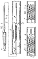
- FIG. 1 depicts the present invention stent 10 mounted on a catheter assembly 12 which is used to deliver the stent and implant it in a body lumen, such as a coronary artery, peripheral artery, or other vessel or lumen within the body.
- the catheter assembly includes a catheter shaft 13 which has a proximal end 14 and a distal end 16.
- the catheter assembly is configured to advance through the patient's vascular system by advancing over a guide wire by any of the well known methods of an over the wire system (not shown) or a well known rapid exchange catheter system, such as the one shown in FIG. 1 .
- Catheter assembly 12 as depicted in FIG. 1 is of the well known rapid exchange type which includes an RX port 20 where the guide wire 18 will exit the catheter.
- the distal end of the guide wire 18 exits the catheter distal end 16 so that the catheter advances along the guide wire on a section of the catheter between the RX port 20 and the catheter distal end 16.
- the guide wire lumen which receives the guide wire is sized for receiving various diameter guide wires to suit a particular application.
- the stent is mounted on the expandable member 22 (balloon) and is crimped tightly thereon so that the stent and expandable member present a low profile diameter for delivery through the arteries.
- Stent 10 of the present invention is used to repair a diseased or damaged arterial wall which may include the plaque 26 as shown in FIG. 1 , or a dissection, or a flap which are commonly found in the coronary arteries, peripheral arteries and other vessels.
- the guide wire 18 is advanced through the patient's vascular system by well known methods so that the distal end of the guide wire is advanced past the plaque or diseased area 26.
- the cardiologist may wish to perform an angioplasty procedure or other procedure (i.e., atherectomy) in order to open the vessel and remodel the diseased area.
- the stent delivery catheter assembly 12 is advanced over the guide wire so that the stent is positioned in the target area.
- the expandable member or balloon 22 is inflated by well known means so that it expands radially outwardly and in turn expands the stent radially outwardly until the stent is apposed to the vessel wall.
- the expandable member is then deflated and the catheter withdrawn from the patient's vascular system.
- the guide wire typically is left in the lumen for post-dilatation procedures, if any, and subsequently is withdrawn from the patient's vascular system.
- the balloon is fully inflated with the stent expanded and pressed against the vessel wall, and in FIG. 3 , the implanted stent remains in the vessel after the balloon has been deflated and the catheter assembly and guide wire have been withdrawn from the patient.
- the stent 10 serves to hold open the artery after the catheter is withdrawn, as illustrated by FIG. 3 . Due to the formation of the stent from an elongated tubular member, the undulating components of the stent are relatively flat in transverse cross-section, so that when the stent is expanded, it is pressed into the wall of the artery and as a result does not interfere with the blood flow through the artery. The stent is pressed into the wall of the artery and will eventually be covered with endothelial cell growth which further minimizes blood flow interference. The undulating portion of the stent provides good tacking characteristics to prevent stent movement within the artery.
- the closely spaced cylindrical elements at regular intervals provide uniform support for the wall of the artery, and consequently are well adapted to tack up and hold in place small flaps or dissections in the wall of the artery, as illustrated in FIGS. 2 and 3 .
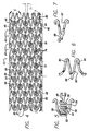
- FIGS. 4-10 depict stent 10 in various configurations.
- stent 10 is shown in a flattened condition so that the pattern can be clearly viewed, even though the stent is never in this form.
- the stent is typically formed from a tubular member, however, it can be formed from a flat sheet such as shown in FIG. 4 and rolled into a cylindrical configuration.
- stent 10 is made up of a plurality of cylindrical rings 40 which extend circumferentially around the stent when it is in a tubular form (see FIG. 8 ).
- the stent has a delivery diameter 42 as shown in FIG. 8 , and an implanted diameter 44 as shown in FIG. 9 .
- Each cylindrical ring 40 has a cylindrical ring proximal end 46 and a cylindrical ring distal end 48.
- the stent is laser cut from a solid tube there are no discreet parts such as the described cylindrical rings. However, it is beneficial for identification and reference to various parts to refer to the cylindrical rings and the following parts of the stent.
- Each cylindrical ring 40 defines a cylindrical plane 50 which is a plane defined by the proximal and distal ends 46, 48 and the circumferential extent as the cylindrical ring travels around the cylinder.
- Each cylindrical ring includes cylindrical outer wall surface 52 which defines the outermost surface of the stent, and cylindrical inner wall surface 53 which defines the innermost surface of the stent. Cylindrical plane 50 follows the cylindrical outer wall surface.
- undulating link 54 is positioned within cylindrical plane 50.
- the undulating links connect one cylindrical ring to an adjacent cylindrical ring and provide overall longitudinal flexibility to the stent due to their unique construction.
- the flexibility of undulating links derives in part from bends 56 connected to straight portions 58 wherein the straight portions are substantially perpendicular to the longitudinal axis of the stent.
- bends 56 and straight portions 5S of the undulating links will permit the stent to flex in the longitudinal direction which substantially enhances delivery of the stent to the target site.
- the number of bends and straight portions can be increased or decreased from that shown, to achieve differing flexibility constructions.
- the undulating link acts like a hinge to provide flexibility.
- a straight link that is parallel to the stent axis typically is not flexible and does not add to the flexibility of the stent.
- Cylindrical rings 40 are nested such that adjacent rings slightly overlap in the longitudinal direction so that one ring is slightly nested within the next ring and so on.
- the degree of nesting is dictated primarily by the length of each cylindrical ring, the number of undulations in the rings, the thickness of the struts that make up the rings, and the radius of curvature, all in conjunction with the crimped or delivery diameter of the stent. If the rings are substantially nested one within the other, it may be difficult to crimp the stent to an appropriate delivery diameter without the various struts overlapping. It is also contemplated that the rings are slightly nested even after the stent is expanded, which enhances vessel wall coverage.
- the stent 10 can be described more particularly as having a plurality of peaks 70 and valleys 72.
- peaks and valleys can vary in number for each ring depending upon the application.
- a lesser number of peaks and valleys are required than if the stent is implanted in a peripheral artery, which has a larger diameter than a coronary artery.
- peaks 70 are in phase 74, meaning that the peaks 70 are substantially aligned along the longitudinal axis of the stent. It may be desirable under certain circumstances to position peaks 70 so that they are out of phase (not shown), that is, the peaks of one ring would be circumferentially offset from the peaks of an adjacent ring. As shown in FIG. 4 , the peaks are circumferentially offset 77 from the valleys and from the undulating link 54. Positioning the peaks, valleys, and undulating links in this manner, provides a stent having uniform expansion capabilities, high radial strength, a high degree offlexibility, and sufficient wall coverage to support the vessel.
- the stent of the invention can be described as having cylindrical rings formed of U-shaped portions 90, Y-shaped portions 92, and W-shaped portions 94.
- the stent is generally laser cut from a solid tube and it typically has no discreet parts, for ease of identification the stent of the invention also can be referred to as having U-, Y-, and W-shaped portions.
- the U-shaped portions have not supporting structure attached thereto.
- the Y-shaped portions, at their base, or apex, have arm 68 extending therefrom and attached to undulating link 54.
- the W portion has at its base or curve portion arm 69 which attaches at the other end of the undulating link.
- the length of the anns attaching the links to the rings can vary.
- the arms should be sized in conjunction with the undulating link so that the link is properly positioned in the W-shaped portion.
- Undulating link 54 is contained within W-shaped portion 94, which should be wide enough to accommodate the undulating link when the stent is crimped so that no portion of the undulating link and the W-portion overlap.
- the undulating link and the W-shaped portion are in the same cylindrical plane 50 as defined by the cylindrical outer wall surface 52 and the cylindrical inner wall surface 53.
- portions of the stent may project radially outwardly when the stent is expanded from its delivery diameter where it is crimped on the balloon to its expanded diameter when it is implanted in the vessel or artery.
- a strut 98 any section of the stent
- projecting edges 96 likely will form when the stent is expanded from its delivery diameter to its implanted diameter.
- no projecting edges will form when a variable thickness strut is used, that is when the strut is thinner than it is wide.
- a rectangular strut 100 forms the stent, as shown in FIGS. 11 and 12 , it is expected that no projecting edges will form upon expansion for this particular stent pattern.
- the stent is formed so that the struts 98 ( FIG. 13 ) have variable thickness along the stent length.
- struts 104 at the ends of the stent may be thicker than the struts 106 in the center of the stent for purposes for radiopacity and to counter balloon expansion.
- the balloon ends have a tendency to inflate at a faster rate than the balloon center, however, with thicker struts at the stent ends the balloon, and hence the stent, will expand more uniformly.
- undulating links 54 will be positioned between adjacent cylindrical rings 40. It is also contemplated, in order to increase stent stability, that straight links 110, as shown in FIG. 14 , in addition to undulating links 54, connect adj acent cylindrical rings. The straight links will provide stability and assist in preventing stent foreshortening, as do the undulating links. Further, the straight links may provide more rigidity in a localized area, such as at the stent ends, such that it may be desirable to incorporate more straight links between the cylindrical rings at the stent ends, than in the center of the stent.
- the cylindrical rings 40 have the ability to flex radially as the vessel pulsates when blood pumps through it.
- the stent can flex longitudinally. The radial and longitudinal flexing of the stent reduces the likelihood that the stent will cause injury to the intima of a coronary artery, which also may have a tendency to reduce the likelihood of restenosis.
- the stent 10 of the present invention can be made in many ways.
- One method of making the stent is to cut a thin-walled tubular member, such as stainless steel tubing to remove portions of the tubing in the desired pattern for the stent, leaving relatively untouched the portions of the metallic tubing which are to form the stent.
- the tubing may be made of suitable biocompatible material such as stainless steel.
- the stainless steel tube may be Alloy type: 316L SS, Special Chemistry per ASTM F138-92 or ASTM F139-92 grade 2. Special Chemistry of type 316L per ASTM F138-92 or ASTM F 139-92 Stainless Steel for Surgical Implants in weight percent.
- the stent diameter is very small, so the tubing from which it is made must necessarily also have a small diameter.
- the stent has an outer diameter on the order of about 1.5mm (0.06 inch) in the unexpanded condition, the same outer diameter of the tubing from which it is made, and can be expanded to an outer diameter of 2.5mm (0.1 inch) or more.
- the wall thickness of the tubing is about 0.076mm (0.003 inch).
- the tubing is mounted in a rotatable collet fixture of a machine-controlled apparatus for positioning the tubing relative to a laser. According to machine-encoded instructions, the tubing is rotated and moved longitudinally relative to the laser which is also machine controlled. The laser selectively removes the material from the tubing by ablation and a pattern is cut into the tube. The tube is therefore cut into the discrete pattern of the finished stent.
- the process of cutting a pattern for the stent into the tubing is automated except for loading and unloading the length of tubing.
- a CNC-opposing collet fixture 22 for axial rotation of the length of tubing is used in conjunction with a CNC X/Y table 25 to move the length of tubing axially relatively to a machine-controlled laser.
- the entire space between collets can be patterned using the CO 2 laser set-up of the foregoing example.
- the program for control of the apparatus is dependent on the particular configuration used and the pattern to be ablated in the coating.
- the tubes are made typically of stainless steel with an outside diameter of 1.5mm to 1.68mm (0.060" to 0.066") and a wall thickness of 0.051 mm (0.002" to 0.004"). These tubes are fixtured under a laser and positioned utilizing a CNC to generate a very intricate and precise pattern. Due to the thin wall and the small geometry of the stent pattern (0.089mm (0.0035”) typical web width), it is necessary to have very precise control of the laser, its power level, the focused spot size, and the precise positioning of the laser cutting path.
- a Q-switched Nd-YAG typically available from Quantronix of Hauppauge, N. Y., that is frequency doubled to produce a green beam at 532 nanometers is utilized.
- Q-switching produces very short pulses ( ⁇ 100nS) of high peak powers (kilowatts), low energy per pulse ( ⁇ 3 mJ), at high pulse rates (up to 40 kHz).
- the frequency doubling of the beam from 1.06 microns to 0.532 microns allows the beam to be focused to a spot size that is 2 times smaller, therefore increasing the power density by a factor of 4 times.
- the system of the present invention makes it possible to adjust the laser parameters to cut narrow kerf width which will minimize the heat input into the material.
- the positioning of the tubular structure requires the use of precision CNC equipment such as that manufactured and sold by Anorad Corporation.
- a unique rotary mechanism has been provided that allows the computer program to be written as if the pattern were being cut from a flat sheet. This allows both circular and linear interpolation to be utilized in programming. Since the finished structure of the stent is very small, a precision drive mechanism is required that supports and drives both ends of the tubular structure as it is cut. Since both ends are driven, they must be aligned and precisely synchronized, otherwise the stent structure would twist and distort as it is being cut.
- the optical system which expands the original laser beam, delivers the beam through a viewing head and focuses the beam onto the surface of the tube, incorporates a coaxial gas jet and nozzle that helps to remove debris from the kerf and cools the region where the beam interacts with the material as the beam cuts and vaporizes the metal. It is also necessary to block the beam as it cuts through the top surface of the tube and prevent the beam, along with the molten metal and debris from the cut, from impinging on the opposite surface of the tube.
- the optical delivery system includes a beam expander to increase the laser beam diameter, a circular polarizer, typically in the form of a quarter wave plate, to eliminate polarization effects in metal cutting, provisions for a spatial filter, a binocular viewing head and focusing lens, and a coaxial gas jet that provides for the introduction of a gas stream that surrounds the focused beam and is directed along the beam axis.
- the coaxial gas jet nozzle (0.46mm (0.018”) I.D.) is centered around the focused beam with approximately 0.25mm (0.010") between the tip of the nozzle and the tubing.
- the jet is pressurized with oxygen at 140kPa (20 psi) and is directed at the tube with the focused laser beam exiting the tip of the nozzle (0.46mm (0.018") dia.).
- the oxygen reacts with the metal to assist in the cutting process very similar to oxyacetylene cutting.
- the focused laser beam acts as an ignition source and controls the reaction of the oxygen with the metal. In this manner, it is possible to cut the material with a very fine kerf with precision.
- a stainless steel mandrel approximatelyx. 0.86mm (0.034”) dia.
- this may be accomplished by inserting a second tube inside the stent tube which has an opening to trap the excess energy in the beam which is transmitted through the kerf along which collecting the debris that is ejected from the laser cut kerf.
- a vacuum or positive pressure can be placed in this shielding tube to remove the collection of debris.
- Another technique that could be utilized to remove the debris from the kerf and cool the surrounding material would be to use the inner beam blocking tube as an internal gas jet. By sealing one end of the tube and making a small hole in the side and placing it directly under the focused laser beam, gas pressure could be applied creating a small jet that would force the debris out of the laser cut kerf from the inside out. This would eliminate any debris from forming or collecting on the inside of the stent structure. It would place all the debris on the outside. With the use of special protective coatings, the resultant debris can be easily removed.
- the gas utilized in the jets may be reactive or non-reactive (inert).
- reactive gas oxygen or compressed air is used. Compressed air is used in this application since it offers more control of the material removed and reduces the thermal effects of the material itself.
- Inert gas such as argon, helium, or nitrogen can be used to eliminate any oxidation of the cut material. The result is a cut edge with no oxidation, but there is usually a tail of molten material that collects along the exit side of the gas jet that must be mechanically or chemically removed after the cutting operation.
- the cutting process utilizing oxygen with the finely focused green beam results in a very narrow kerf (approx. 13 ⁇ m (0.0005")) with the molten slag re-solidifying along the cut. This traps the cut out scrap of the pattern requiring further processing.
- a mandrel is placed down the center of the tube during the cleaning/scrap removal process.
- the stent structure are rinsed in water. They are now ready for electropolishing.
- the stents are preferably electrochemically polished in an acidic aqueous solution such as a solution of ELECTRO-GLO#300, sold by ELECTRO-GLO Co., Inc. in Chicago, Ill., which is a mixture of sulfuric acid, carboxylic acids, phosphates, corrosion inhibitors and a biodegradable surface active agent.
- the bath temperature is maintained at about 43°-1330° C (110° -1350° F) and the current density is about 0.06 to about 0.23 amps per cm 2 (about 0. 4 to about 1.5 amps per in 2 ).
- Cathode to anode area should be at least about two to one.
- the stents may be further treated if desired, for example by applying a biocompatible coating.
- both focused laser spot size and depth of focus can be controlled by selecting beam diameter and focal length for the focusing lens. It will be apparent that increasing laser beam diameter, or reducing lens focal length, reduces spot size at the cost of depth of field.
- Direct laser cutting produces edges which are essentially perpendicular to the axis of the laser cutting beam, in contrast with chemical etching and the like which produce pattern edges which are angled.
- the laser cutting process essentially provides strut cross-sections, from cut-to-cut, which are square or rectangular, rather than trapezoidal.
- cylindrical rings 40 are comprised of struts 98 which have generally rectangular cross-sections 100 when the stent is laser cut from a tubular member.
- the struts have generally perpendicular edges formed by the laser cut.
- the resulting stent structure provides superior performance.
- stent of the present invention can be used, such as chemical etching; electric discharge machining; laser cutting a flat sheet and rolling it into a cylinder; and the like, all of which are well known in the art at this time.
- the stent of the present invention also can be made from metal alloys other than stainless steel, such as shape memory alloys.
- Shape memory alloys are well known and include, but are not limited to, nickel titanium and nickel/titanium/vanadium. Any of the shape memory alloys can be formed into a tube and laser cut in order to form the pattern of the stent of the present invention.
- the shape memory alloys of the stent of the present invention can include the type known as thermoelastic martensitic transformation, or display stress-induced martensite. These types of alloys are well known in the art and need not be further described here.
- a stent formed of shape memory alloys can be delivered using a balloon catheter of the type described herein, or in the case of stress induced martensite, be delivered via a catheter without a balloon or a sheath catheter.
Landscapes
- Health & Medical Sciences (AREA)
- Engineering & Computer Science (AREA)
- Biomedical Technology (AREA)
- Life Sciences & Earth Sciences (AREA)
- General Health & Medical Sciences (AREA)
- Transplantation (AREA)
- Heart & Thoracic Surgery (AREA)
- Vascular Medicine (AREA)
- Cardiology (AREA)
- Animal Behavior & Ethology (AREA)
- Oral & Maxillofacial Surgery (AREA)
- Public Health (AREA)
- Veterinary Medicine (AREA)
- Physics & Mathematics (AREA)
- Optics & Photonics (AREA)
- Media Introduction/Drainage Providing Device (AREA)
- Prostheses (AREA)
- Materials For Medical Uses (AREA)
Claims (26)
- Endoprothèse vasculaire souple (10) à utiliser dans une lumière d'un corps, comprenant :une pluralité de bagues cylindriques (40) interconnectées pour former l'endoprothèse (10), chaque bague cylindrique (40) ayant un premier diamètre (42) de pose et un second diamètre (44) élargi, chaque bague cylindrique (40) ayant une extrémité proximale (46) et une extrémité distale (48) et définissant un plan cylindrique (50) s'étendant de manière circonférentielle entre l'extrémité proximale (46) et l'extrémité distale (43) de la bague cylindrique (40) ; etun moyen destiné à attacher chaque bague cylindrique (40) à une bague cylindrique (40) adjacente, le moyen d'attache étant positionné essentiellement dans le plan cylindrique (50) de la bague cylindrique (40) ;dans laquelle les bagues cylindriques (40) ont en outre des parties (94) en forme de W ayant des entretoises incurvées positionnées circonférentiellement adjacentes au moyen d'attache de la bague cylindrique (40) ; et dans laquelle
chaque bague cylindrique (40) est emboîtée dans une bague cylindrique (40) adjacente, et le moyen d'attache comprend au moins une liaison ondulée (54) entre des bagues cylindriques (40) adjacentes. - Endoprothèse de la revendication 1, dans laquelle au moins une liaison ondulée (54) comprend au moins un coude (56) relié à une partie (58) essentiellement droite, la partie (58) essentiellement droite étant essentiellement perpendiculaire à l'axe longitudinal de l'endoprothèse.
- Endoprothèse de l'une quelconque des revendications précédentes, dans laquelle chaque bague cylindrique (40) comprend une pluralité de pointes (70) et de dépressions (72).
- Endoprothèse de la revendication 3, dans laquelle les pointes (70) de chaque bague cylindrique (40) sont en phase avec les pointes (70) d'une bague cylindrique (40) adjacente.
- Endoprothèse de la revendication 1 dans laquelle les bagues cylindriques (40) ont en outre une pluralité de parties (90) en forme de U, et de parties (92) en forme de Y.
- Endoprothèse de la revendication 2, dans laquelle la partie (58) essentiellement droite de l'au moins une liaison ondulée (54) est perpendiculaire à l'axe longitudinal de l'endoprothèse lorsque l'endoprothèse (10) se trouve dans la configuration au second diamètre élargi.
- Endoprothèse de la revendication 1, dans laquelle l'endoprothèse (10) est formée à partir d'un tube.
- Endoprothèse de la revendication 1, dans laquelle l'endoprothèse (10) est formée d'un alliage métallique.
- Endoprothèse de la revendication 1, dans laquelle l'endoprothèse (10) est formée d'acier inoxydable.
- Endoprothèse de la revendication 1, dans laquelle l'endoprothèse (10) est formée d'un alliage à mémoire de forme.
- Endoprothèse de la revendication 10, dans laquelle l'endoprothèse (10) est formée du groupe d'alliages à mémoire de forme constitué de nickel-titane et de nickel-titane-vanadium.
- Endoprothèse de la revendication 1, dans laquelle l'endoprothèse (10) est formée d'un alliage métallique pseudo-élastique.
- Endoprothèse de la revendication 12, dans laquelle l'endoprothèse (10) est formée du groupe d'alliages métalliques pseudo-élastiques constitué de nickel-titane et de nickel-titane-vanadium.
- Endoprothèse de la revendication 5, dans laquelle les parties (92) en forme de Y sont formées de la combinaison des parties (90) en forme de U et des liaisons ondulées (54).
- Endoprothèse de la revendication 1, dans laquelle les parties (94) en forme de W comportent au moins une partie des liaisons ondulées (54).
- Endoprothèse de la revendication 1, dans laquelle au moins une liaison ondulée (54) est positionnée dans au moins une partie (94) en forme de W.
- Endoprothèse de la revencicaiton 16, dans laquelle l'au moins une partie (94) en forme de W a une paire d'entretoises reliées à une partie incurvée, l'au moins une liaison ondulée (54) étant positionnée entre les entretoises et attachée à la partie incurvée.
- Endoprothèse de la revendication 2, dans laquelle la partie (58) essentiellement droite de l'au moins une liaison ondulée (54) est perpendiculaire à l'axe longitudinal de l'endoprothèse lorsque l'endoprothèse (10) se trouve dans la configuration au premier diamètre de pose.
- Endoprothèse de la revendication 18, dans laquelle la partie (58) essentiellement droite de l'au moins une liaison ondulée (54) est perpendiculaire à l'axe longitudinal de l'endoprothèse lorsque l'endoprothèse (10) se trouve dans la configuration au second diamètre élargi.
- Endoprothèse de l'une quelconque des revendications 1, 5, ou 19, dans laquelle au moins l'une des liaisons ondulées (54) comprend une pluralité de coudes.
- Endoprothèse de la revendication 1 ou de la revendication 5, dans laquelle les liaisons ondulées (54) sont configurées pour procurer de la flexibilité à l'endoprothèse (10).
- Endoprothèse de la revendication 1 ou de la revendication 5, dans laquelle les bagues cylindriques (40) sont configurées pour procurer de la flexibilité à l'endoprothèse (10).
- Endoprothèse de la revendication 1 ou de la revendication 5, dans laquelle les bagues cylindriques (40) et les liaisons ondulées (54) sont définies par une pluralité d'entretoises.
- Endoprothèse de la revendication 23, dans laquelle au moins l'une des entretoises a une section transversale variable.
- Endoprothèse de la revendication 23, dans laquelle au moins l'une des entretoises a une section transversale qui est différente de certaines des autres entretoises.
- Endoprothèse de la revendication 23, dans laquelle au moins une partie des entretoises ont une épaisseur radiale variable.
Priority Applications (2)
| Application Number | Priority Date | Filing Date | Title |
|---|---|---|---|
| EP10180430.0A EP2277478A3 (fr) | 2000-05-03 | 2001-04-16 | Endoprothèse intravasculaire |
| EP10002927.1A EP2198812A3 (fr) | 2000-05-03 | 2001-04-16 | Intravaskulärer Stent |
Applications Claiming Priority (3)
| Application Number | Priority Date | Filing Date | Title |
|---|---|---|---|
| US564151 | 1983-12-22 | ||
| US09/564,151 US6616689B1 (en) | 2000-05-03 | 2000-05-03 | Intravascular stent |
| PCT/US2001/012155 WO2001082835A2 (fr) | 2000-05-03 | 2001-04-16 | Endoprothese intravasculaire |
Related Child Applications (1)
| Application Number | Title | Priority Date | Filing Date |
|---|---|---|---|
| EP10002927.1 Division-Into | 2010-03-19 |
Publications (2)
| Publication Number | Publication Date |
|---|---|
| EP1278481A2 EP1278481A2 (fr) | 2003-01-29 |
| EP1278481B1 true EP1278481B1 (fr) | 2010-05-05 |
Family
ID=24253350
Family Applications (3)
| Application Number | Title | Priority Date | Filing Date |
|---|---|---|---|
| EP01926978A Revoked EP1278481B1 (fr) | 2000-05-03 | 2001-04-16 | Endoprothese intravasculaire |
| EP10002927.1A Withdrawn EP2198812A3 (fr) | 2000-05-03 | 2001-04-16 | Intravaskulärer Stent |
| EP10180430.0A Withdrawn EP2277478A3 (fr) | 2000-05-03 | 2001-04-16 | Endoprothèse intravasculaire |
Family Applications After (2)
| Application Number | Title | Priority Date | Filing Date |
|---|---|---|---|
| EP10002927.1A Withdrawn EP2198812A3 (fr) | 2000-05-03 | 2001-04-16 | Intravaskulärer Stent |
| EP10180430.0A Withdrawn EP2277478A3 (fr) | 2000-05-03 | 2001-04-16 | Endoprothèse intravasculaire |
Country Status (7)
| Country | Link |
|---|---|
| US (5) | US6616689B1 (fr) |
| EP (3) | EP1278481B1 (fr) |
| JP (1) | JP3725480B2 (fr) |
| AT (1) | ATE466551T1 (fr) |
| AU (1) | AU2001253476A1 (fr) |
| DE (1) | DE60142040D1 (fr) |
| WO (1) | WO2001082835A2 (fr) |
Families Citing this family (124)
| Publication number | Priority date | Publication date | Assignee | Title |
|---|---|---|---|---|
| US6682554B2 (en) | 1998-09-05 | 2004-01-27 | Jomed Gmbh | Methods and apparatus for a stent having an expandable web structure |
| US7815763B2 (en) * | 2001-09-28 | 2010-10-19 | Abbott Laboratories Vascular Enterprises Limited | Porous membranes for medical implants and methods of manufacture |
| US6755856B2 (en) | 1998-09-05 | 2004-06-29 | Abbott Laboratories Vascular Enterprises Limited | Methods and apparatus for stenting comprising enhanced embolic protection, coupled with improved protection against restenosis and thrombus formation |
| US7887578B2 (en) | 1998-09-05 | 2011-02-15 | Abbott Laboratories Vascular Enterprises Limited | Stent having an expandable web structure |
| EP1132058A1 (fr) | 2000-03-06 | 2001-09-12 | Advanced Laser Applications Holding S.A. | Prothèse intravasculaire |
| US9522217B2 (en) | 2000-03-15 | 2016-12-20 | Orbusneich Medical, Inc. | Medical device with coating for capturing genetically-altered cells and methods for using same |
| US8088060B2 (en) | 2000-03-15 | 2012-01-03 | Orbusneich Medical, Inc. | Progenitor endothelial cell capturing with a drug eluting implantable medical device |
| US8460367B2 (en) | 2000-03-15 | 2013-06-11 | Orbusneich Medical, Inc. | Progenitor endothelial cell capturing with a drug eluting implantable medical device |
| AU2002219569B2 (en) * | 2001-01-15 | 2005-05-05 | Terumo Kabushiki Kaisha | Stent |
| US6939373B2 (en) * | 2003-08-20 | 2005-09-06 | Advanced Cardiovascular Systems, Inc. | Intravascular stent |
| US6866805B2 (en) | 2001-12-27 | 2005-03-15 | Advanced Cardiovascular Systems, Inc. | Hybrid intravascular stent |
| US7163553B2 (en) | 2001-12-28 | 2007-01-16 | Advanced Cardiovascular Systems, Inc. | Intravascular stent and method of use |
| US7691461B1 (en) * | 2002-04-01 | 2010-04-06 | Advanced Cardiovascular Systems, Inc. | Hybrid stent and method of making |
| JP4570315B2 (ja) * | 2002-06-17 | 2010-10-27 | 埼玉県 | チタン系金属製品の製造方法及びチタン系金属製品 |
| US7959671B2 (en) | 2002-11-05 | 2011-06-14 | Merit Medical Systems, Inc. | Differential covering and coating methods |
| US7637942B2 (en) | 2002-11-05 | 2009-12-29 | Merit Medical Systems, Inc. | Coated stent with geometry determinated functionality and method of making the same |
| US7875068B2 (en) * | 2002-11-05 | 2011-01-25 | Merit Medical Systems, Inc. | Removable biliary stent |
| EP1663377A4 (fr) * | 2003-08-07 | 2011-09-07 | Merit Medical Systems Inc | Dispositif medical therapeutique, son deploiement et son utilisation |
| US7763011B2 (en) * | 2003-12-22 | 2010-07-27 | Boston Scientific Scimed, Inc. | Variable density braid stent |
| US7402170B2 (en) * | 2003-12-30 | 2008-07-22 | Scimed Life Systems, Inc. | Crimp and weld wire connection |
| US20050185061A1 (en) * | 2004-02-23 | 2005-08-25 | Andy Baker | Self photographing camera system |
| US8747879B2 (en) | 2006-04-28 | 2014-06-10 | Advanced Cardiovascular Systems, Inc. | Method of fabricating an implantable medical device to reduce chance of late inflammatory response |
| US7731890B2 (en) | 2006-06-15 | 2010-06-08 | Advanced Cardiovascular Systems, Inc. | Methods of fabricating stents with enhanced fracture toughness |
| US9517149B2 (en) | 2004-07-26 | 2016-12-13 | Abbott Cardiovascular Systems Inc. | Biodegradable stent with enhanced fracture toughness |
| US7971333B2 (en) | 2006-05-30 | 2011-07-05 | Advanced Cardiovascular Systems, Inc. | Manufacturing process for polymetric stents |
| US7887579B2 (en) | 2004-09-29 | 2011-02-15 | Merit Medical Systems, Inc. | Active stent |
| US7344560B2 (en) | 2004-10-08 | 2008-03-18 | Boston Scientific Scimed, Inc. | Medical devices and methods of making the same |
| US7731654B2 (en) | 2005-05-13 | 2010-06-08 | Merit Medical Systems, Inc. | Delivery device with viewing window and associated method |
| DE102006017028A1 (de) * | 2006-04-11 | 2007-10-18 | Admedes Schuessler Gmbh | Selbstexpandierender Stent mit Federstruktur |
| US8778009B2 (en) * | 2006-10-06 | 2014-07-15 | Abbott Cardiovascular Systems Inc. | Intravascular stent |
| US7780798B2 (en) | 2006-10-13 | 2010-08-24 | Boston Scientific Scimed, Inc. | Medical devices including hardened alloys |
| US9622888B2 (en) | 2006-11-16 | 2017-04-18 | W. L. Gore & Associates, Inc. | Stent having flexibly connected adjacent stent elements |
| US8388673B2 (en) * | 2008-05-02 | 2013-03-05 | Abbott Cardiovascular Systems Inc. | Polymeric stent |
| US8016874B2 (en) | 2007-05-23 | 2011-09-13 | Abbott Laboratories Vascular Enterprises Limited | Flexible stent with elevated scaffolding properties |
| US8128679B2 (en) | 2007-05-23 | 2012-03-06 | Abbott Laboratories Vascular Enterprises Limited | Flexible stent with torque-absorbing connectors |
| US8216209B2 (en) | 2007-05-31 | 2012-07-10 | Abbott Cardiovascular Systems Inc. | Method and apparatus for delivering an agent to a kidney |
| US9364586B2 (en) | 2007-05-31 | 2016-06-14 | Abbott Cardiovascular Systems Inc. | Method and apparatus for improving delivery of an agent to a kidney |
| US9144509B2 (en) | 2007-05-31 | 2015-09-29 | Abbott Cardiovascular Systems Inc. | Method and apparatus for delivering an agent to a kidney |
| US9149610B2 (en) | 2007-05-31 | 2015-10-06 | Abbott Cardiovascular Systems Inc. | Method and apparatus for improving delivery of an agent to a kidney |
| JP5210609B2 (ja) * | 2007-11-30 | 2013-06-12 | テルモ株式会社 | 生体器官拡張器具 |
| CA2709278A1 (fr) * | 2007-12-15 | 2009-06-25 | Endospan Ltd. | Enveloppe extravasculaire pour le traitement d'un anevrisme de l'aorte en association avec un stent-greffon endovasculaire et procedes associes |
| EP2219564B1 (fr) * | 2007-12-20 | 2019-07-24 | Abbott Laboratories Vascular Enterprises Limited | Endoprothèse présentant une architecture stable et endoprothèse présentant des raccords flexibles |
| US7850726B2 (en) | 2007-12-20 | 2010-12-14 | Abbott Laboratories Vascular Enterprises Limited | Endoprosthesis having struts linked by foot extensions |
| US8337544B2 (en) | 2007-12-20 | 2012-12-25 | Abbott Laboratories Vascular Enterprises Limited | Endoprosthesis having flexible connectors |
| US8920488B2 (en) * | 2007-12-20 | 2014-12-30 | Abbott Laboratories Vascular Enterprises Limited | Endoprosthesis having a stable architecture |
| GB2475494B (en) | 2009-11-18 | 2011-11-23 | Cook William Europ | Stent graft and introducer assembly |
| GB2476451A (en) * | 2009-11-19 | 2011-06-29 | Cook William Europ | Stent Graft |
| US9226813B2 (en) | 2007-12-26 | 2016-01-05 | Cook Medical Technologies Llc | Low profile non-symmetrical stent |
| US8992593B2 (en) * | 2007-12-26 | 2015-03-31 | Cook Medical Technologies Llc | Apparatus and methods for deployment of a modular stent-graft system |
| US8728145B2 (en) | 2008-12-11 | 2014-05-20 | Cook Medical Technologies Llc | Low profile non-symmetrical stents and stent-grafts |
| US8574284B2 (en) | 2007-12-26 | 2013-11-05 | Cook Medical Technologies Llc | Low profile non-symmetrical bare alignment stents with graft |
| US9180030B2 (en) | 2007-12-26 | 2015-11-10 | Cook Medical Technologies Llc | Low profile non-symmetrical stent |
| US8926688B2 (en) | 2008-01-11 | 2015-01-06 | W. L. Gore & Assoc. Inc. | Stent having adjacent elements connected by flexible webs |
| US20100241069A1 (en) | 2009-03-19 | 2010-09-23 | Abbott Cardiovascular Systems Inc. | Ostial lesion stent delivery system |
| CA2961767C (fr) | 2009-06-23 | 2018-08-14 | Endospan Ltd. | Protheses vasculaires utilisees pour le traitement des anevrismes |
| US8114149B2 (en) * | 2009-10-20 | 2012-02-14 | Svelte Medical Systems, Inc. | Hybrid stent with helical connectors |
| US9757263B2 (en) * | 2009-11-18 | 2017-09-12 | Cook Medical Technologies Llc | Stent graft and introducer assembly |
| CA2782357C (fr) | 2009-11-30 | 2018-06-05 | Endospan Ltd. | Systeme d'endoprothese a multiples composants destine a etre implante dans un vaisseau sanguin avec de multiples ramifications |
| US8808353B2 (en) | 2010-01-30 | 2014-08-19 | Abbott Cardiovascular Systems Inc. | Crush recoverable polymer scaffolds having a low crossing profile |
| US8568471B2 (en) | 2010-01-30 | 2013-10-29 | Abbott Cardiovascular Systems Inc. | Crush recoverable polymer scaffolds |
| WO2011095979A1 (fr) | 2010-02-08 | 2011-08-11 | Endospan Ltd. | Application d'énergie thermique pour la prévention et le contrôle d'endofuites dans des endoprothèses |
| US8882824B2 (en) * | 2010-04-20 | 2014-11-11 | Cg Bio Co., Ltd. | Expanding vascular stent |
| AU2011349578B2 (en) | 2010-12-23 | 2016-06-30 | Twelve, Inc. | System for mitral valve repair and replacement |
| EP2579810A4 (fr) | 2011-02-03 | 2014-07-30 | Endospan Ltd | Dispositifs médicaux implantables constitués de matériau à mémoire de forme |
| WO2012111006A1 (fr) * | 2011-02-17 | 2012-08-23 | Endospan Ltd. | Bandes vasculaires et systèmes pour leur pose |
| WO2012117395A1 (fr) | 2011-03-02 | 2012-09-07 | Endospan Ltd. | Anneau extravasculaire à contrainte réduite pour traiter un anévrisme aortique |
| US8574287B2 (en) | 2011-06-14 | 2013-11-05 | Endospan Ltd. | Stents incorporating a plurality of strain-distribution locations |
| EP2723273B1 (fr) | 2011-06-21 | 2021-10-27 | Twelve, Inc. | Dispositifs de valvule cardiaque prosthétiques |
| US8951298B2 (en) | 2011-06-21 | 2015-02-10 | Endospan Ltd. | Endovascular system with circumferentially-overlapping stent-grafts |
| US8726483B2 (en) | 2011-07-29 | 2014-05-20 | Abbott Cardiovascular Systems Inc. | Methods for uniform crimping and deployment of a polymer scaffold |
| US9839510B2 (en) | 2011-08-28 | 2017-12-12 | Endospan Ltd. | Stent-grafts with post-deployment variable radial displacement |
| GB2494632A (en) | 2011-09-09 | 2013-03-20 | Isis Innovation | Stent and method of inserting a stent into a delivery catheter |
| US11202704B2 (en) | 2011-10-19 | 2021-12-21 | Twelve, Inc. | Prosthetic heart valve devices, prosthetic mitral valves and associated systems and methods |
| US9763780B2 (en) | 2011-10-19 | 2017-09-19 | Twelve, Inc. | Devices, systems and methods for heart valve replacement |
| AU2012325813A1 (en) | 2011-10-19 | 2014-04-03 | Twelve, Inc. | Prosthetic heart valve devices, prosthetic mitral valves and associated systems and methods |
| US9039757B2 (en) | 2011-10-19 | 2015-05-26 | Twelve, Inc. | Prosthetic heart valve devices, prosthetic mitral valves and associated systems and methods |
| US9655722B2 (en) | 2011-10-19 | 2017-05-23 | Twelve, Inc. | Prosthetic heart valve devices, prosthetic mitral valves and associated systems and methods |
| CN103889369B (zh) | 2011-10-19 | 2016-09-14 | 托尔福公司 | 用于心脏瓣膜置换术的装置 |
| US9427339B2 (en) | 2011-10-30 | 2016-08-30 | Endospan Ltd. | Triple-collar stent-graft |
| US9597204B2 (en) | 2011-12-04 | 2017-03-21 | Endospan Ltd. | Branched stent-graft system |
| US9579198B2 (en) | 2012-03-01 | 2017-02-28 | Twelve, Inc. | Hydraulic delivery systems for prosthetic heart valve devices and associated methods |
| KR102157676B1 (ko) | 2012-05-14 | 2020-09-21 | 씨. 알. 바드, 인크. | 균일하게 팽창가능한 스텐트 |
| WO2013171730A1 (fr) | 2012-05-15 | 2013-11-21 | Endospan Ltd. | Endoprothèse à éléments de fixation confinés radialement pour la pose |
| KR101489263B1 (ko) | 2014-02-26 | 2015-02-04 | 썬텍 주식회사 | 고분자 스텐트의 제조방법 및 폴리락트산 고분자 스텐트 |
| US9629735B2 (en) | 2012-11-16 | 2017-04-25 | W. L. Gore & Associates, Inc. | Flexible endoluminal device |
| WO2014108895A2 (fr) | 2013-01-08 | 2014-07-17 | Endospan Ltd. | Minimisation de la migration d'une endoprothèse au cours de l'implantation |
| USD723165S1 (en) | 2013-03-12 | 2015-02-24 | C. R. Bard, Inc. | Stent |
| WO2014189974A1 (fr) | 2013-05-20 | 2014-11-27 | Twelve, Inc. | Dispositifs de valvule cardiaque pouvant être implantée, dispositifs de réparation de valve mitrale, et systèmes et procédés associés |
| EP3010451B1 (fr) | 2013-06-21 | 2021-11-24 | Boston Scientific Scimed, Inc. | Endoprothèse à connecteur de déflexion |
| WO2015075708A1 (fr) | 2013-11-19 | 2015-05-28 | Endospan Ltd. | Système d'endoprothèse à blocage de l'expansion radiale |
| WO2015098443A1 (fr) * | 2013-12-25 | 2015-07-02 | 株式会社 京都医療設計 | Endoprothèse vasculaire |
| US10123863B2 (en) | 2014-03-28 | 2018-11-13 | Cook Medical Technologies Llc | Mechanism for applying high radial force in less-elastic medical devices |
| US10299948B2 (en) | 2014-11-26 | 2019-05-28 | W. L. Gore & Associates, Inc. | Balloon expandable endoprosthesis |
| EP3068339B1 (fr) | 2014-12-18 | 2017-11-01 | Endospan Ltd. | Stent-greffe endovasculaire avec tube lateral resistant a la fatigue |
| CN107920895B (zh) | 2015-08-21 | 2020-06-26 | 托尔福公司 | 可植入心脏瓣膜装置、二尖瓣修复装置以及相关系统和方法 |
| US10758381B2 (en) | 2016-03-31 | 2020-09-01 | Vesper Medical, Inc. | Intravascular implants |
| WO2017189276A1 (fr) | 2016-04-29 | 2017-11-02 | Medtronic Vascular Inc. | Dispositifs de valve cardiaque prothétiques et systèmes et procédés associés |
| US10568752B2 (en) | 2016-05-25 | 2020-02-25 | W. L. Gore & Associates, Inc. | Controlled endoprosthesis balloon expansion |
| CN109475418A (zh) * | 2016-07-13 | 2019-03-15 | 波士顿科学国际有限公司 | 用于在与近旁手术相邻的血管内维持畅通性的器械和方法 |
| EP3381416B1 (fr) | 2017-03-29 | 2020-07-22 | Cook Medical Technologies LLC | Prothèse avec stent souple |
| US10702378B2 (en) | 2017-04-18 | 2020-07-07 | Twelve, Inc. | Prosthetic heart valve device and associated systems and methods |
| US10433961B2 (en) | 2017-04-18 | 2019-10-08 | Twelve, Inc. | Delivery systems with tethers for prosthetic heart valve devices and associated methods |
| US10575950B2 (en) | 2017-04-18 | 2020-03-03 | Twelve, Inc. | Hydraulic systems for delivering prosthetic heart valve devices and associated methods |
| US10792151B2 (en) | 2017-05-11 | 2020-10-06 | Twelve, Inc. | Delivery systems for delivering prosthetic heart valve devices and associated methods |
| US10646338B2 (en) | 2017-06-02 | 2020-05-12 | Twelve, Inc. | Delivery systems with telescoping capsules for deploying prosthetic heart valve devices and associated methods |
| US10709591B2 (en) | 2017-06-06 | 2020-07-14 | Twelve, Inc. | Crimping device and method for loading stents and prosthetic heart valves |
| JP7414529B2 (ja) | 2017-06-07 | 2024-01-16 | シファメド・ホールディングス・エルエルシー | 血管内流体移動デバイス、システム、および使用方法 |
| US10729541B2 (en) | 2017-07-06 | 2020-08-04 | Twelve, Inc. | Prosthetic heart valve devices and associated systems and methods |
| US10786352B2 (en) | 2017-07-06 | 2020-09-29 | Twelve, Inc. | Prosthetic heart valve devices and associated systems and methods |
| US10238513B2 (en) | 2017-07-19 | 2019-03-26 | Abbott Cardiovascular Systems Inc. | Intravascular stent |
| US10849769B2 (en) | 2017-08-23 | 2020-12-01 | Vesper Medical, Inc. | Non-foreshortening stent |
| US11628076B2 (en) | 2017-09-08 | 2023-04-18 | Vesper Medical, Inc. | Hybrid stent |
| US11357650B2 (en) | 2019-02-28 | 2022-06-14 | Vesper Medical, Inc. | Hybrid stent |
| US10271977B2 (en) | 2017-09-08 | 2019-04-30 | Vesper Medical, Inc. | Hybrid stent |
| CN111556763B (zh) | 2017-11-13 | 2023-09-01 | 施菲姆德控股有限责任公司 | 血管内流体运动装置、系统 |
| WO2019138788A1 (fr) * | 2018-01-11 | 2019-07-18 | 国立研究開発法人宇宙航空研究開発機構 | Structure déployable et son procédé de déploiement |
| JP7410034B2 (ja) | 2018-02-01 | 2024-01-09 | シファメド・ホールディングス・エルエルシー | 血管内血液ポンプならびに使用および製造の方法 |
| US11364134B2 (en) | 2018-02-15 | 2022-06-21 | Vesper Medical, Inc. | Tapering stent |
| US10500078B2 (en) | 2018-03-09 | 2019-12-10 | Vesper Medical, Inc. | Implantable stent |
| EP3787553B1 (fr) | 2018-05-02 | 2023-08-16 | W.L. Gore & Associates, Inc. | Éléments d'expansion pour dispositifs implantables et systèmes |
| US11964145B2 (en) | 2019-07-12 | 2024-04-23 | Shifamed Holdings, Llc | Intravascular blood pumps and methods of manufacture and use |
| WO2021016372A1 (fr) | 2019-07-22 | 2021-01-28 | Shifamed Holdings, Llc | Pompes à sang intravasculaires à entretoises et procédés d'utilisation et de fabrication |
| EP4034221A4 (fr) | 2019-09-25 | 2023-10-11 | Shifamed Holdings, LLC | Pompes à sang de cathéter et boîtiers de pompe pliables |
| US11724089B2 (en) | 2019-09-25 | 2023-08-15 | Shifamed Holdings, Llc | Intravascular blood pump systems and methods of use and control thereof |
Family Cites Families (123)
| Publication number | Priority date | Publication date | Assignee | Title |
|---|---|---|---|---|
| DE3136725A1 (de) | 1981-09-16 | 1983-03-31 | Robert Bosch Gmbh, 7000 Stuttgart | Verfahren und vorrichtung zur steuerung eines unter last schaltbaren getriebes |
| US4580568A (en) | 1984-10-01 | 1986-04-08 | Cook, Incorporated | Percutaneous endovascular stent and method for insertion thereof |
| US5102417A (en) | 1985-11-07 | 1992-04-07 | Expandable Grafts Partnership | Expandable intraluminal graft, and method and apparatus for implanting an expandable intraluminal graft |
| US4931615A (en) | 1988-12-02 | 1990-06-05 | General Electric Company | Apparatus for machining intricate feature cuts in thin walled tubular parts |
| US5292331A (en) | 1989-08-24 | 1994-03-08 | Applied Vascular Engineering, Inc. | Endovascular support device |
| US5674278A (en) | 1989-08-24 | 1997-10-07 | Arterial Vascular Engineering, Inc. | Endovascular support device |
| IE73670B1 (en) | 1989-10-02 | 1997-07-02 | Medtronic Inc | Articulated stent |
| CA2380683C (fr) * | 1991-10-28 | 2006-08-08 | Advanced Cardiovascular Systems, Inc. | Empreintes extensibles et leur methode de fabrication |
| US5342387A (en) | 1992-06-18 | 1994-08-30 | American Biomed, Inc. | Artificial support for a blood vessel |
| JPH08507243A (ja) | 1993-07-23 | 1996-08-06 | クック インコーポレイティッド | シート材料から形成されたパターンを有するフレキシブルなステント |
| AU6987594A (en) | 1993-08-18 | 1995-03-14 | W.L. Gore & Associates, Inc. | A tubular intraluminal graft |
| ES2135520T3 (es) | 1993-11-04 | 1999-11-01 | Bard Inc C R | Protesis vascular no migrante. |
| JP2703510B2 (ja) * | 1993-12-28 | 1998-01-26 | アドヴァンスド カーディオヴァスキュラー システムズ インコーポレーテッド | 拡大可能なステント及びその製造方法 |
| US6051020A (en) | 1994-02-09 | 2000-04-18 | Boston Scientific Technology, Inc. | Bifurcated endoluminal prosthesis |
| US5643312A (en) | 1994-02-25 | 1997-07-01 | Fischell Robert | Stent having a multiplicity of closed circular structures |
| ES2116680T3 (es) | 1994-02-25 | 1998-07-16 | Fischell Robert | Extensor vascular provisto de una pluralidad de estructuras circulares cerradas. |
| US5449373A (en) | 1994-03-17 | 1995-09-12 | Medinol Ltd. | Articulated stent |
| US5733303A (en) | 1994-03-17 | 1998-03-31 | Medinol Ltd. | Flexible expandable stent |
| US5843120A (en) | 1994-03-17 | 1998-12-01 | Medinol Ltd. | Flexible-expandable stent |
| DE4418336A1 (de) | 1994-05-26 | 1995-11-30 | Angiomed Ag | Stent |
| US5836964A (en) | 1996-10-30 | 1998-11-17 | Medinol Ltd. | Stent fabrication method |
| CA2134997C (fr) | 1994-11-03 | 2009-06-02 | Ian M. Penn | Stent |
| CA2213403C (fr) | 1995-02-22 | 2007-01-16 | Menlo Care, Inc. | Prothese endovasculaire a treillis dilatable revetu |
| US7204848B1 (en) | 1995-03-01 | 2007-04-17 | Boston Scientific Scimed, Inc. | Longitudinally flexible expandable stent |
| JP3505603B2 (ja) | 1995-03-01 | 2004-03-08 | サイメド ライフ システムズ,インコーポレイテッド | 縦に柔軟な拡張し得る改善ステント |
| US6053943A (en) | 1995-12-08 | 2000-04-25 | Impra, Inc. | Endoluminal graft with integral structural support and method for making same |
| US6039755A (en) | 1997-02-05 | 2000-03-21 | Impra, Inc., A Division Of C.R. Bard, Inc. | Radially expandable tubular polytetrafluoroethylene grafts and method of making same |
| CA2215027C (fr) | 1995-03-10 | 2007-04-10 | Impra, Inc. | Extenseur encapsule endoluminal, son procede de fabrication, et son procede d'implantation endoluminale |
| CA2171896C (fr) * | 1995-03-17 | 2007-05-15 | Scott C. Anderson | Extenseur a ancrage multiple |
| ES2119527T5 (es) | 1995-04-01 | 2006-11-16 | Variomed Ag | Dispositivo stent para la implantacion transluminal en organos huecos. |
| AU5675196A (en) | 1995-06-08 | 1997-01-09 | Bard Galway Limited | Endovascular stent |
| RU2157146C2 (ru) | 1995-06-13 | 2000-10-10 | ВИЛЬЯМ КУК Европа, A/S | Устройство для имплантации в сосудах и полых органах (его варианты) |
| US5776161A (en) | 1995-10-16 | 1998-07-07 | Instent, Inc. | Medical stents, apparatus and method for making same |
| AU7458596A (en) | 1995-10-20 | 1997-05-07 | Bandula Wijay | Vascular stent |
| US5607442A (en) | 1995-11-13 | 1997-03-04 | Isostent, Inc. | Stent with improved radiopacity and appearance characteristics |
| US5824040A (en) | 1995-12-01 | 1998-10-20 | Medtronic, Inc. | Endoluminal prostheses and therapies for highly variable body lumens |
| US5800512A (en) | 1996-01-22 | 1998-09-01 | Meadox Medicals, Inc. | PTFE vascular graft |
| US6258116B1 (en) | 1996-01-26 | 2001-07-10 | Cordis Corporation | Bifurcated axially flexible stent |
| US5895406A (en) | 1996-01-26 | 1999-04-20 | Cordis Corporation | Axially flexible stent |
| US5938682A (en) | 1996-01-26 | 1999-08-17 | Cordis Corporation | Axially flexible stent |
| CA2192520A1 (fr) * | 1996-03-05 | 1997-09-05 | Ian M. Penn | Tringle extensible et methode de mise en place de ladite tringle |
| EP1066804B1 (fr) * | 1996-03-05 | 2004-07-14 | Evysio Medical Devices Ulc | Stent extensible |
| US5868780A (en) | 1996-03-22 | 1999-02-09 | Lashinski; Robert D. | Stents for supporting lumens in living tissue |
| US6152957A (en) | 1996-04-26 | 2000-11-28 | Jang; G. David | Intravascular stent |
| US20020058990A1 (en) | 2000-09-23 | 2002-05-16 | Jang G. David | Intravascular stent consists of stairstep expansion strut pairs and double stairstep diagonal connecting struts contralaterally extended from expansion struts |
| US6039756A (en) | 1996-04-26 | 2000-03-21 | Jang; G. David | Intravascular stent |
| DE69727004T2 (de) | 1996-05-08 | 2004-11-25 | Sorin Biomedica Cardio S.P.A., Saluggia | Ein Stent für Angioplastie |
| US5669932A (en) | 1996-05-29 | 1997-09-23 | Isostent, Inc. | Means for accurately positioning an expandable stent |
| BR9702255A (pt) | 1996-05-31 | 1999-02-17 | Bard Galway Ltd | Estensores endovasculares bifurcados e métodos e aparelho para colocação dos mesmos |
| US5697971A (en) | 1996-06-11 | 1997-12-16 | Fischell; Robert E. | Multi-cell stent with cells having differing characteristics |
| US5922020A (en) | 1996-08-02 | 1999-07-13 | Localmed, Inc. | Tubular prosthesis having improved expansion and imaging characteristics |
| US5755781A (en) | 1996-08-06 | 1998-05-26 | Iowa-India Investments Company Limited | Embodiments of multiple interconnected stents |
| US5807404A (en) | 1996-09-19 | 1998-09-15 | Medinol Ltd. | Stent with variable features to optimize support and method of making such stent |
| US6099561A (en) | 1996-10-21 | 2000-08-08 | Inflow Dynamics, Inc. | Vascular and endoluminal stents with improved coatings |
| US5868781A (en) | 1996-10-22 | 1999-02-09 | Scimed Life Systems, Inc. | Locking stent |
| EP0884985B1 (fr) | 1996-10-28 | 2003-06-25 | BIOTRONIK Mess- und Therapiegeräte GmbH & Co Ingenieurbüro Berlin | Extenseur |
| FR2758253B1 (fr) * | 1997-01-10 | 1999-04-02 | Nycomed Lab Sa | Dispositif implantable pour le traitement d'un conduit corporel |
| US5925061A (en) * | 1997-01-13 | 1999-07-20 | Gore Enterprise Holdings, Inc. | Low profile vascular stent |
| US5827321A (en) | 1997-02-07 | 1998-10-27 | Cornerstone Devices, Inc. | Non-Foreshortening intraluminal prosthesis |
| AU6464298A (en) * | 1997-03-13 | 1998-09-29 | United States Surgical Corporation | Flexible tissue supporting device |
| US5810872A (en) | 1997-03-14 | 1998-09-22 | Kanesaka; Nozomu | Flexible stent |
| US5853419A (en) | 1997-03-17 | 1998-12-29 | Surface Genesis, Inc. | Stent |
| US5868783A (en) | 1997-04-16 | 1999-02-09 | Numed, Inc. | Intravascular stent with limited axial shrinkage |
| US6033433A (en) | 1997-04-25 | 2000-03-07 | Scimed Life Systems, Inc. | Stent configurations including spirals |
| US6451049B2 (en) | 1998-04-29 | 2002-09-17 | Sorin Biomedica Cardio, S.P.A. | Stents for angioplasty |
| US5741327A (en) | 1997-05-06 | 1998-04-21 | Global Therapeutics, Inc. | Surgical stent featuring radiopaque markers |
| DE29708689U1 (de) | 1997-05-15 | 1997-07-17 | Jomed Implantate GmbH, 72414 Rangendingen | Koronarer Stent |
| DE29708803U1 (de) | 1997-05-17 | 1997-07-31 | Jomed Implantate GmbH, 72414 Rangendingen | Radial aufweitbarer Stent zur Implantierung in ein Körpergefäß im Bereich einer Gefäßverzweigung |
| DE29708879U1 (de) | 1997-05-20 | 1997-07-31 | Jomed Implantate GmbH, 72414 Rangendingen | Koronarer Stent |
| US5913895A (en) | 1997-06-02 | 1999-06-22 | Isostent, Inc. | Intravascular stent with enhanced rigidity strut members |
| US5843175A (en) | 1997-06-13 | 1998-12-01 | Global Therapeutics, Inc. | Enhanced flexibility surgical stent |
| EP0890346A1 (fr) | 1997-06-13 | 1999-01-13 | Gary J. Becker | Endoprothèse intraluminale expansible |
| ES2214600T3 (es) | 1997-06-30 | 2004-09-16 | Medex Holding Gmbh | Implante intraluminal. |
| US6059822A (en) | 1997-08-22 | 2000-05-09 | Uni-Cath Inc. | Stent with different mesh patterns |
| ES2290995T3 (es) * | 1997-09-24 | 2008-02-16 | Med Institute, Inc. | Endoprotesis radialmente expandible. |
| US6086611A (en) | 1997-09-25 | 2000-07-11 | Ave Connaught | Bifurcated stent |
| US5948016A (en) | 1997-09-25 | 1999-09-07 | Jang; G. David | Intravascular stent with non-parallel slots |
| US6042606A (en) | 1997-09-29 | 2000-03-28 | Cook Incorporated | Radially expandable non-axially contracting surgical stent |
| US6013091A (en) | 1997-10-09 | 2000-01-11 | Scimed Life Systems, Inc. | Stent configurations |
| US5893887A (en) | 1997-10-14 | 1999-04-13 | Iowa-India Investments Company Limited | Stent for positioning at junction of bifurcated blood vessel and method of making |
| US5967986A (en) | 1997-11-25 | 1999-10-19 | Vascusense, Inc. | Endoluminal implant with fluid flow sensing capability |
| DE19749691A1 (de) * | 1997-10-28 | 1999-04-29 | Biotronik Mess & Therapieg | Stent |
| US6033435A (en) | 1997-11-03 | 2000-03-07 | Divysio Solutions Ulc | Bifurcated stent and method for the manufacture and delivery of same |
| US6309414B1 (en) * | 1997-11-04 | 2001-10-30 | Sorin Biomedica Cardio S.P.A. | Angioplasty stents |
| US6330884B1 (en) * | 1997-11-14 | 2001-12-18 | Transvascular, Inc. | Deformable scaffolding multicellular stent |
| US6129754A (en) | 1997-12-11 | 2000-10-10 | Uni-Cath Inc. | Stent for vessel with branch |
| US6022374A (en) | 1997-12-16 | 2000-02-08 | Cardiovasc, Inc. | Expandable stent having radiopaque marker and method |
| US5964798A (en) | 1997-12-16 | 1999-10-12 | Cardiovasc, Inc. | Stent having high radial strength |
| US6342067B1 (en) | 1998-01-09 | 2002-01-29 | Nitinol Development Corporation | Intravascular stent having curved bridges for connecting adjacent hoops |
| US6129755A (en) | 1998-01-09 | 2000-10-10 | Nitinol Development Corporation | Intravascular stent having an improved strut configuration |
| US6179867B1 (en) * | 1998-01-16 | 2001-01-30 | Advanced Cardiovascular Systems, Inc. | Flexible stent and method of use |
| US6113627A (en) | 1998-02-03 | 2000-09-05 | Jang; G. David | Tubular stent consists of horizontal expansion struts and contralaterally attached diagonal-connectors |
| AU2579999A (en) | 1998-02-03 | 1999-08-16 | Cardiovascular Interventional Systems, Inc. | Tubular stent consists of non-parallel expansion struts and contralaterally attached diagonal connectors |
| US6123721A (en) | 1998-02-17 | 2000-09-26 | Jang; G. David | Tubular stent consists of chevron-shape expansion struts and ipsilaterally attached M-frame connectors |
| US5931866A (en) | 1998-02-24 | 1999-08-03 | Frantzen; John J. | Radially expandable stent featuring accordion stops |
| FR2775182B1 (fr) | 1998-02-25 | 2000-07-28 | Legona Anstalt | Dispositif formant andoprothese intracorporelle endoluminale, en particulier aortique abdominale |
| US5938697A (en) | 1998-03-04 | 1999-08-17 | Scimed Life Systems, Inc. | Stent having variable properties |
| US5935162A (en) | 1998-03-16 | 1999-08-10 | Medtronic, Inc. | Wire-tubular hybrid stent |
| US6179868B1 (en) | 1998-03-27 | 2001-01-30 | Janet Burpee | Stent with reduced shortening |
| US6241762B1 (en) | 1998-03-30 | 2001-06-05 | Conor Medsystems, Inc. | Expandable medical device with ductile hinges |
| US6019789A (en) | 1998-04-01 | 2000-02-01 | Quanam Medical Corporation | Expandable unit cell and intraluminal stent |
| US6206916B1 (en) | 1998-04-15 | 2001-03-27 | Joseph G. Furst | Coated intraluminal graft |
| US6093203A (en) | 1998-05-13 | 2000-07-25 | Uflacker; Renan | Stent or graft support structure for treating bifurcated vessels having different diameter portions and methods of use and implantation |
| US6099559A (en) | 1998-05-28 | 2000-08-08 | Medtronic Ave, Inc. | Endoluminal support assembly with capped ends |
| US6066169A (en) | 1998-06-02 | 2000-05-23 | Ave Connaught | Expandable stent having articulated connecting rods |
| US6261319B1 (en) | 1998-07-08 | 2001-07-17 | Scimed Life Systems, Inc. | Stent |
| US5911754A (en) | 1998-07-24 | 1999-06-15 | Uni-Cath Inc. | Flexible stent with effective strut and connector patterns |
| US6099539A (en) | 1998-07-27 | 2000-08-08 | Thomas J. Fogarty | Surgical clamp pad with interdigitating teeth |
| US6093199A (en) | 1998-08-05 | 2000-07-25 | Endovascular Technologies, Inc. | Intra-luminal device for treatment of body cavities and lumens and method of use |
| US6206915B1 (en) * | 1998-09-29 | 2001-03-27 | Medtronic Ave, Inc. | Drug storing and metering stent |
| US6042597A (en) | 1998-10-23 | 2000-03-28 | Scimed Life Systems, Inc. | Helical stent design |
| US6190403B1 (en) | 1998-11-13 | 2001-02-20 | Cordis Corporation | Low profile radiopaque stent with increased longitudinal flexibility and radial rigidity |
| US6083259A (en) | 1998-11-16 | 2000-07-04 | Frantzen; John J. | Axially non-contracting flexible radially expandable stent |
| US6099455A (en) | 1998-11-25 | 2000-08-08 | Isostent, Inc. | Radioisotope stent with non-radioactive end sections |
| US6187034B1 (en) | 1999-01-13 | 2001-02-13 | John J. Frantzen | Segmented stent for flexible stent delivery system |
| EP1229859A2 (fr) * | 1999-09-23 | 2002-08-14 | Advanced Stent Technologies, Inc. | Systeme et procede de bifurcation d'une endoprothese vasculaire |
| WO2001026584A1 (fr) | 1999-10-14 | 2001-04-19 | United Stenting, Inc. | Extenseurs dotes d'elements de renfort multicouches |
| EP1315850A4 (fr) | 2000-07-13 | 2003-09-10 | Discovery Commercial Entpr Ltd | Procede et dispositif de fabrication de stents extensibles a usage medical |
| US20020032478A1 (en) | 2000-08-07 | 2002-03-14 | Percardia, Inc. | Myocardial stents and related methods of providing direct blood flow from a heart chamber to a coronary vessel |
| US6699278B2 (en) | 2000-09-22 | 2004-03-02 | Cordis Corporation | Stent with optimal strength and radiopacity characteristics |
| DE60136868D1 (de) | 2000-09-23 | 2009-01-15 | Boston Scient Scimed Inc | Intravaskulärer Stent |
| DE60125800T2 (de) | 2000-09-25 | 2007-10-11 | Boston Scientific Scimed, Inc., Maple Grove | Intravaskulärer stent |
| EP1322256B2 (fr) | 2000-09-25 | 2011-12-21 | Boston Scientific Scimed, Inc. | Dispositif d'extenseur intravasculaire |
-
2000
- 2000-05-03 US US09/564,151 patent/US6616689B1/en not_active Expired - Lifetime
-
2001
- 2001-04-16 DE DE60142040T patent/DE60142040D1/de not_active Expired - Lifetime
- 2001-04-16 EP EP01926978A patent/EP1278481B1/fr not_active Revoked
- 2001-04-16 WO PCT/US2001/012155 patent/WO2001082835A2/fr active Application Filing
- 2001-04-16 JP JP2001579713A patent/JP3725480B2/ja not_active Expired - Fee Related
- 2001-04-16 AU AU2001253476A patent/AU2001253476A1/en not_active Abandoned
- 2001-04-16 EP EP10002927.1A patent/EP2198812A3/fr not_active Withdrawn
- 2001-04-16 AT AT01926978T patent/ATE466551T1/de not_active IP Right Cessation
- 2001-04-16 EP EP10180430.0A patent/EP2277478A3/fr not_active Withdrawn
-
2003
- 2003-05-15 US US10/438,687 patent/US7951188B2/en not_active Expired - Fee Related
-
2011
- 2011-05-13 US US13/106,983 patent/US8449598B2/en not_active Expired - Fee Related
-
2013
- 2013-05-08 US US13/889,949 patent/US9408727B2/en not_active Expired - Fee Related
-
2016
- 2016-07-13 US US15/209,348 patent/US20160317333A1/en not_active Abandoned
Also Published As
| Publication number | Publication date |
|---|---|
| US8449598B2 (en) | 2013-05-28 |
| EP2198812A2 (fr) | 2010-06-23 |
| US20110213458A1 (en) | 2011-09-01 |
| US9408727B2 (en) | 2016-08-09 |
| JP2003531673A (ja) | 2003-10-28 |
| EP2198812A3 (fr) | 2013-10-16 |
| DE60142040D1 (de) | 2010-06-17 |
| EP2277478A2 (fr) | 2011-01-26 |
| EP1278481A2 (fr) | 2003-01-29 |
| US20140155986A1 (en) | 2014-06-05 |
| JP3725480B2 (ja) | 2005-12-14 |
| AU2001253476A1 (en) | 2001-11-12 |
| US20160317333A1 (en) | 2016-11-03 |
| WO2001082835A3 (fr) | 2002-05-16 |
| US6616689B1 (en) | 2003-09-09 |
| WO2001082835A2 (fr) | 2001-11-08 |
| US7951188B2 (en) | 2011-05-31 |
| EP2277478A3 (fr) | 2013-12-25 |
| ATE466551T1 (de) | 2010-05-15 |
| US20030199968A1 (en) | 2003-10-23 |
Similar Documents
| Publication | Publication Date | Title |
|---|---|---|
| EP1278481B1 (fr) | Endoprothese intravasculaire | |
| US20170312106A1 (en) | Intravascular stent | |
| US6629994B2 (en) | Intravascular stent | |
| US6635083B1 (en) | Stent with non-linear links and method of use | |
| US6656220B1 (en) | Intravascular stent | |
| US6929660B1 (en) | Intravascular stent | |
| US6602284B2 (en) | Variable strength stent | |
| US6179867B1 (en) | Flexible stent and method of use | |
| US6776794B1 (en) | Stent pattern with mirror image | |
| US6626935B1 (en) | Intravascular stent |
Legal Events
| Date | Code | Title | Description |
|---|---|---|---|
| PUAI | Public reference made under article 153(3) epc to a published international application that has entered the european phase |
Free format text: ORIGINAL CODE: 0009012 |
|
| 17P | Request for examination filed |
Effective date: 20021120 |
|
| AK | Designated contracting states |
Designated state(s): AT BE CH CY DE DK ES FI FR GB GR IE IT LI LU MC NL PT SE TR |
|
| AX | Request for extension of the european patent |
Extension state: AL LT LV MK RO SI |
|
| 17Q | First examination report despatched |
Effective date: 20050309 |
|
| RAP1 | Party data changed (applicant data changed or rights of an application transferred) |
Owner name: ABBOTT CARDIOVASCULAR SYSTEMS INC. |
|
| RIC1 | Information provided on ipc code assigned before grant |
Ipc: A61F 2/82 20060101AFI20090515BHEP |
|
| GRAP | Despatch of communication of intention to grant a patent |
Free format text: ORIGINAL CODE: EPIDOSNIGR1 |
|
| RIC1 | Information provided on ipc code assigned before grant |
Ipc: A61F 2/82 20060101AFI20091008BHEP Ipc: A61F 2/90 20060101ALN20091008BHEP |
|
| GRAS | Grant fee paid |
Free format text: ORIGINAL CODE: EPIDOSNIGR3 |
|
| GRAA | (expected) grant |
Free format text: ORIGINAL CODE: 0009210 |
|
| AK | Designated contracting states |
Kind code of ref document: B1 Designated state(s): AT BE CH CY DE DK ES FI FR GB GR IE IT LI LU MC NL PT SE TR |
|
| REG | Reference to a national code |
Ref country code: GB Ref legal event code: FG4D |
|
| REG | Reference to a national code |
Ref country code: CH Ref legal event code: EP |
|
| REG | Reference to a national code |
Ref country code: IE Ref legal event code: FG4D |
|
| REG | Reference to a national code |
Ref country code: CH Ref legal event code: NV Representative=s name: KIRKER & CIE S.A. |
|
| REF | Corresponds to: |
Ref document number: 60142040 Country of ref document: DE Date of ref document: 20100617 Kind code of ref document: P |
|
| REG | Reference to a national code |
Ref country code: NL Ref legal event code: VDEP Effective date: 20100505 |
|
| PG25 | Lapsed in a contracting state [announced via postgrant information from national office to epo] |
Ref country code: ES Free format text: LAPSE BECAUSE OF FAILURE TO SUBMIT A TRANSLATION OF THE DESCRIPTION OR TO PAY THE FEE WITHIN THE PRESCRIBED TIME-LIMIT Effective date: 20100816 Ref country code: SE Free format text: LAPSE BECAUSE OF FAILURE TO SUBMIT A TRANSLATION OF THE DESCRIPTION OR TO PAY THE FEE WITHIN THE PRESCRIBED TIME-LIMIT Effective date: 20100505 Ref country code: NL Free format text: LAPSE BECAUSE OF FAILURE TO SUBMIT A TRANSLATION OF THE DESCRIPTION OR TO PAY THE FEE WITHIN THE PRESCRIBED TIME-LIMIT Effective date: 20100505 |
|
| PG25 | Lapsed in a contracting state [announced via postgrant information from national office to epo] |
Ref country code: AT Free format text: LAPSE BECAUSE OF FAILURE TO SUBMIT A TRANSLATION OF THE DESCRIPTION OR TO PAY THE FEE WITHIN THE PRESCRIBED TIME-LIMIT Effective date: 20100505 Ref country code: FI Free format text: LAPSE BECAUSE OF FAILURE TO SUBMIT A TRANSLATION OF THE DESCRIPTION OR TO PAY THE FEE WITHIN THE PRESCRIBED TIME-LIMIT Effective date: 20100505 |
|
| PG25 | Lapsed in a contracting state [announced via postgrant information from national office to epo] |
Ref country code: CY Free format text: LAPSE BECAUSE OF FAILURE TO SUBMIT A TRANSLATION OF THE DESCRIPTION OR TO PAY THE FEE WITHIN THE PRESCRIBED TIME-LIMIT Effective date: 20100505 Ref country code: GR Free format text: LAPSE BECAUSE OF FAILURE TO SUBMIT A TRANSLATION OF THE DESCRIPTION OR TO PAY THE FEE WITHIN THE PRESCRIBED TIME-LIMIT Effective date: 20100806 |
|
| PG25 | Lapsed in a contracting state [announced via postgrant information from national office to epo] |
Ref country code: PT Free format text: LAPSE BECAUSE OF FAILURE TO SUBMIT A TRANSLATION OF THE DESCRIPTION OR TO PAY THE FEE WITHIN THE PRESCRIBED TIME-LIMIT Effective date: 20100906 Ref country code: DK Free format text: LAPSE BECAUSE OF FAILURE TO SUBMIT A TRANSLATION OF THE DESCRIPTION OR TO PAY THE FEE WITHIN THE PRESCRIBED TIME-LIMIT Effective date: 20100505 |
|
| PLBI | Opposition filed |
Free format text: ORIGINAL CODE: 0009260 |
|
| PG25 | Lapsed in a contracting state [announced via postgrant information from national office to epo] |
Ref country code: BE Free format text: LAPSE BECAUSE OF FAILURE TO SUBMIT A TRANSLATION OF THE DESCRIPTION OR TO PAY THE FEE WITHIN THE PRESCRIBED TIME-LIMIT Effective date: 20100505 |
|
| PLAX | Notice of opposition and request to file observation + time limit sent |
Free format text: ORIGINAL CODE: EPIDOSNOBS2 |
|
| 26 | Opposition filed |
Opponent name: BOSTON SCIENTIFIC CORPORATION Effective date: 20110204 |
|
| PG25 | Lapsed in a contracting state [announced via postgrant information from national office to epo] |
Ref country code: IT Free format text: LAPSE BECAUSE OF FAILURE TO SUBMIT A TRANSLATION OF THE DESCRIPTION OR TO PAY THE FEE WITHIN THE PRESCRIBED TIME-LIMIT Effective date: 20100505 |
|
| REG | Reference to a national code |
Ref country code: DE Ref legal event code: R026 Ref document number: 60142040 Country of ref document: DE Effective date: 20110204 |
|
| PLAF | Information modified related to communication of a notice of opposition and request to file observations + time limit |
Free format text: ORIGINAL CODE: EPIDOSCOBS2 |
|
| PLBB | Reply of patent proprietor to notice(s) of opposition received |
Free format text: ORIGINAL CODE: EPIDOSNOBS3 |
|
| PG25 | Lapsed in a contracting state [announced via postgrant information from national office to epo] |
Ref country code: MC Free format text: LAPSE BECAUSE OF NON-PAYMENT OF DUE FEES Effective date: 20110430 |
|
| PGFP | Annual fee paid to national office [announced via postgrant information from national office to epo] |
Ref country code: GB Payment date: 20130326 Year of fee payment: 13 |
|
| PG25 | Lapsed in a contracting state [announced via postgrant information from national office to epo] |
Ref country code: LU Free format text: LAPSE BECAUSE OF NON-PAYMENT OF DUE FEES Effective date: 20110416 |
|
| PGFP | Annual fee paid to national office [announced via postgrant information from national office to epo] |
Ref country code: IE Payment date: 20130418 Year of fee payment: 13 Ref country code: DE Payment date: 20130430 Year of fee payment: 13 Ref country code: CH Payment date: 20130426 Year of fee payment: 13 |
|
| PGFP | Annual fee paid to national office [announced via postgrant information from national office to epo] |
Ref country code: FR Payment date: 20130417 Year of fee payment: 13 |
|
| REG | Reference to a national code |
Ref country code: DE Ref legal event code: R064 Ref document number: 60142040 Country of ref document: DE Ref country code: DE Ref legal event code: R103 Ref document number: 60142040 Country of ref document: DE |
|
| PG25 | Lapsed in a contracting state [announced via postgrant information from national office to epo] |
Ref country code: TR Free format text: LAPSE BECAUSE OF FAILURE TO SUBMIT A TRANSLATION OF THE DESCRIPTION OR TO PAY THE FEE WITHIN THE PRESCRIBED TIME-LIMIT Effective date: 20100505 |
|
| RDAF | Communication despatched that patent is revoked |
Free format text: ORIGINAL CODE: EPIDOSNREV1 |
|
| RDAG | Patent revoked |
Free format text: ORIGINAL CODE: 0009271 |
|
| STAA | Information on the status of an ep patent application or granted ep patent |
Free format text: STATUS: PATENT REVOKED |
|
| REG | Reference to a national code |
Ref country code: CH Ref legal event code: PL |
|
| 27W | Patent revoked |
Effective date: 20130919 |
|
| GBPR | Gb: patent revoked under art. 102 of the ep convention designating the uk as contracting state |
Effective date: 20130919 |
|
| REG | Reference to a national code |
Ref country code: DE Ref legal event code: R107 Ref document number: 60142040 Country of ref document: DE Effective date: 20140424 |
|
| PG25 | Lapsed in a contracting state [announced via postgrant information from national office to epo] |
Ref country code: CH Free format text: LAPSE BECAUSE OF THE APPLICANT RENOUNCES Effective date: 20100505 Ref country code: LI Free format text: LAPSE BECAUSE OF THE APPLICANT RENOUNCES Effective date: 20100505 |