EP1276580B2 - Fraise - Google Patents
Fraise Download PDFInfo
- Publication number
- EP1276580B2 EP1276580B2 EP01926281.5A EP01926281A EP1276580B2 EP 1276580 B2 EP1276580 B2 EP 1276580B2 EP 01926281 A EP01926281 A EP 01926281A EP 1276580 B2 EP1276580 B2 EP 1276580B2
- Authority
- EP
- European Patent Office
- Prior art keywords
- cutting
- clearance angle
- members
- angle
- milling tool
- Prior art date
- Legal status (The legal status is an assumption and is not a legal conclusion. Google has not performed a legal analysis and makes no representation as to the accuracy of the status listed.)
- Expired - Lifetime
Links
Images

Classifications
-
- B—PERFORMING OPERATIONS; TRANSPORTING
- B23—MACHINE TOOLS; METAL-WORKING NOT OTHERWISE PROVIDED FOR
- B23C—MILLING
- B23C5/00—Milling-cutters
- B23C5/16—Milling-cutters characterised by physical features other than shape
- B23C5/20—Milling-cutters characterised by physical features other than shape with removable cutter bits or teeth or cutting inserts
-
- B—PERFORMING OPERATIONS; TRANSPORTING
- B23—MACHINE TOOLS; METAL-WORKING NOT OTHERWISE PROVIDED FOR
- B23C—MILLING
- B23C5/00—Milling-cutters
- B23C5/006—Details of the milling cutter body
-
- B—PERFORMING OPERATIONS; TRANSPORTING
- B23—MACHINE TOOLS; METAL-WORKING NOT OTHERWISE PROVIDED FOR
- B23C—MILLING
- B23C5/00—Milling-cutters
- B23C5/02—Milling-cutters characterised by the shape of the cutter
- B23C5/10—Shank-type cutters, i.e. with an integral shaft
- B23C5/109—Shank-type cutters, i.e. with an integral shaft with removable cutting inserts
-
- Y—GENERAL TAGGING OF NEW TECHNOLOGICAL DEVELOPMENTS; GENERAL TAGGING OF CROSS-SECTIONAL TECHNOLOGIES SPANNING OVER SEVERAL SECTIONS OF THE IPC; TECHNICAL SUBJECTS COVERED BY FORMER USPC CROSS-REFERENCE ART COLLECTIONS [XRACs] AND DIGESTS
- Y10—TECHNICAL SUBJECTS COVERED BY FORMER USPC
- Y10T—TECHNICAL SUBJECTS COVERED BY FORMER US CLASSIFICATION
- Y10T407/00—Cutters, for shaping
- Y10T407/19—Rotary cutting tool
- Y10T407/1906—Rotary cutting tool including holder [i.e., head] having seat for inserted tool
- Y10T407/1908—Face or end mill
- Y10T407/191—Plural simultaneously usable separable tools in common seat or common clamp actuator for plural simultaneously usable tools
-
- Y—GENERAL TAGGING OF NEW TECHNOLOGICAL DEVELOPMENTS; GENERAL TAGGING OF CROSS-SECTIONAL TECHNOLOGIES SPANNING OVER SEVERAL SECTIONS OF THE IPC; TECHNICAL SUBJECTS COVERED BY FORMER USPC CROSS-REFERENCE ART COLLECTIONS [XRACs] AND DIGESTS
- Y10—TECHNICAL SUBJECTS COVERED BY FORMER USPC
- Y10T—TECHNICAL SUBJECTS COVERED BY FORMER US CLASSIFICATION
- Y10T407/00—Cutters, for shaping
- Y10T407/19—Rotary cutting tool
- Y10T407/1906—Rotary cutting tool including holder [i.e., head] having seat for inserted tool
- Y10T407/1926—Plural simultaneously usable separable tools in common seat or common clamp actuator for plural simultaneously usable tools
Definitions
- This invention relates to a milling tool of the type that comprises a body that is rotatable around a geometrical centre axis with an envelope surface along which is arranged at least one set of tangentially spaced-apart cutting members, each one of which features a chip forming edge formed adjacent to a flank surface, which edge extends between axially spaced-apart ends (see for example US-A-5 368 418 ).
- the individual tool can only be designed with one single diameter for each purpose, if both the requirement for a determined angle of the shoulder as well as the requirement for an optimized rake and clearance geometry from a stability point of view are to be met. It should also be pointed out that, in practice, unstable milling tools give a mediocre machining precision in respect to the flatness of the machined surface. An unstable, vibrating milling tool thus gives rise to at least small wavy formations on the machined surface of the workpiece.
- a primary aim of the invention is to provide a milling tool which is capable of working in a stable, substantially vibration free way and at the same time generate machined surfaces having a high degree of flatness. It is also an aim to provide a milling tool which at a given diameter can be used for, for instance, different types of shoulders while at the same time maintaining a good machining precision as well as a stable operation.
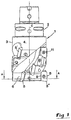
- numeral 1 generally designates a cutter body or shell, which is rotatable around a geometrical centre axis C.
- the cutter body 1 includes a front main part 3, the envelope surface 4 of which in the example shown has a cylindrical basic shape.
- the part 3 can also have another rotationally symmetrical basic shape than cylindrical, e.g. conical.
- the tool consists of a long edge milling cutter which, in a known way, includes a plurality of rows of axially spaced-apart cutting insert members which in this case are in the form of detachably mounted cutting inserts 5 which are indexable.
- the cutting inserts in each individual row are housed in a helicoidal recess formed along the envelope surface of the cutter body, which recess serves as a chip channel 6 in the area up-stream of the cutting inserts.
- a separate seat 7 for each individual cutting insert, there is a separate seat 7 (see fig 3 ). Said seats are placed in such a way that the cutting inserts in the mounted state overlap each other axially, as is clearly seen in fig 1 .
- the tool includes three rows of inserts having four individual cutting inserts in each row.
- a set of three cutting inserts 5, 5', 5" acts. These can either be exactly situated in one and the same axial position in the common plane or be somewhat displaced in relation to each other in the axial direction to partly overlap each other during operation.
- Each individual cutting insert 5 has an active cutting edge 8 situated between a rake surface 9 and a flank surface 10.
- the same has two opposite, substantially parallel edges 8.
- the individual cutting edge can either be straight or slightly helicoidal in order to, depending on the cutting edge angle of the cutting inserts, follow the generally cylindrical or rotationally symmetrical basic shape of the milling cutter body.
- the individual cutting insert can to advantage be secured in the appurtenant seat 7 by means of a screw 11.
- the individual seat 7 is, in the main, defined by a bottom surface 12 against which the bottom side 13 (see fig 2 ) of the cutting insert is pressable, as well as an abutment surface 14 against which an inactive flank surface 5 of the cutting insert can be pressed in order to determine the radial position of the cutting insert relative the cutter body.
- Characteristic of the invention is that the different cutting inserts 5, 5', 5" of the individual sets of cutting inserts have different clearance angles. More precisely, one of the cutting inserts, i.e. the cutting insert 5, has a clearance angle ⁇ which is larger than the clearance angle ⁇ of the other cutting inserts 5', 5" of the same set.
- clearance angle it should, in the usual way, be understood the angle which is formed between the flank surface 10 of the individual cutting body and a conceived tangential line T through the cutting edge 8.
- the angle ⁇ of the cutting insert 5 can be within the range of 5-25°, and suitably within the commonly accepted area of 7-15°.
- the clearance angle in question can amount to 10 to 11 °.
- the clearance angle ⁇ of the other two cutting inserts 5', 5" should, in turn, be within the range of 0,5-5°, suitably 1-4°. In practice, the clearance angle ⁇ can advantageously amount to 2 to 3 °. In this connection, it should be pointed out that the above mentioned clearance angles are valid regardless of whether the cutting inserts have straight cutting edges and plane flank surfaces or curved cutting edges and bent flank surfaces.
- the cutting insert 5 which has the largest clearance angle ⁇ is located or made in such a way that the distance L between the cutting edge 8 and the centre axis C of the milling cutter body is somewhat larger than the corresponding distance L 1 between the centre axis and the cutting edges of the two other cutting inserts 5', 5" which have the smaller clearance angle ⁇ .
- the difference between the values L and L 1 is small, although clearly marked. More precisely, the difference in distance should be within the range of 0,01-0,08 mm, preferably 0,03-0,06 mm and amount to approx. 0,05 mm.
- the seat 7 for the cutting insert 5 having the larger clearance angle ⁇ is formed with a bottom surface 12 extending at a comparatively flack angle to a conceived radial plane R that intersects a given point along the bottom surface, at the same time as the corresponding bottom surface 12 at the seats 7', 7" for the cutting inserts 5', 5" extends at a steeper angle to the analogous radial planes R.
- the abutment surface 14 at the seat 7 is located at a radial distance from the centre axis C of the milling cutter body that is larger than the radial distance between the centre axis and the corresponding abutment surfaces 14 of the seats 7', 7".
- the edge 8 of the cutting insert 5 is located at a somewhat larger distance from the centre axis than the corresponding edges of the cutting inserts 5', 5" having a minimal clearance angle. Thanks to the bottom surfaces 12 of the seats 7', 7" extending at a steeper angle to the appurtenant radial plane than the bottom surface 12 of the seat 7, the two cutting bodies 5', 5" will, at the mounting in the seat, be angled somewhat forwards in comparison with the cutting insert 5 and in this way be located with the flank surfaces 10 thereof in the smaller clearance angle ⁇ in relation to the tangent line T.
- the cutting inserts having a reduced clearance angle will induce damping when the tool turns in relation to the machined surface of the work piece, and thereby guarantee stability in the tool, whilst the cutting insert with the maximum clearance angle works with a more easy-cutting action while guaranteeing the requisite machining precision.
- the cutting insert having the maximum clearance angle is so placed and made in respect to the radial angle, axial rake angle and setting angle that the tool related geometry thereof generates the desired final form of a machined, plane surface or shoulder.
- the cutting insert having the maximum clearance angle generates a genuine plane surface with a predetermined angle in relation to the end face of the milling tool.
- the other cutting inserts in the tool, i.e. the cutting inserts having the reduced clearance angle have in turn the role of meeting the requirements for an optimum stability, i.e. a vibration free operation, without themselves giving the desired final precision in respect of the flatness of the machined surface.
- the invention is not solely restricted to the embodiment described above and shown in the drawings.
- the invention can be applied not only in connection with long edge milling cutters, but also to other milling tools, e.g. square shoulder facemills, of the type that includes a set of tangentially spaced-apart radial cutting inserts.
- milling tools e.g. square shoulder facemills
- the invention is also applicable to tools having fixed, e.g. brazed cutting inserts. It is even feasible to form the requisite cutting members, particularly chip forming edges, in the proper milling body if this is made of a hard material, e.g. cemented carbide.
- cutting members such as it is used in the subsequent claims, should be interpreted in the widest sense and be regarded as including not only separately manufactured cutting inserts irrespective of whether these are detachably mounted or fixedly attached, but also such cutting members which are integrated into the actual milling body.
- the general idea according to the invention can also be realized by means of suitable formed cutting inserts of two different types, which are mounted in identically formed and placed seats. In the embodiment example, only three cutting members are shown in the set of cutting members in question. In practice, the number of cutting members of each set can be considerably larger than only three. In such cases, more than one cutting member can be formed having the larger clearance angle, while other cutting members have reduced clearance angles (e.g.
- the number of cutting members having the maximum clearance angle should be smaller than the number of cutting members having the reduced clearance angle.
Claims (5)
- Fraise comprenant un corps (1) pouvant tourner autour d'un axe central géométrique (C) et ayant une surface enveloppe (4) le long de laquelle est disposée au moins une série d'éléments de coupe (5, 5', 5") espacés de façon tangentielle, dont chacun présente une arête de formation de copeaux (8) formée de manière adjacente à une surface de flanc (10), la dite arête s'étendant entre des extrémités axialement espacées, la surface de flanc (10) pour au moins un premier élément de coupe (5) de ladite série s'étendant selon un premier angle de dépouille (α) par rapport à une ligne tangente imaginaire (T) traversant l'arête (8), et en ce que la surface de flanc (10) pour l'autre élément ou les autres éléments de coupe (5', 5") de la série s'étend selon un second angle de dépouille (β) qui est inférieur au dit premier angle de dépouille (α), caractérisée en ce que l'élément de coupe individuel (5) ayant l'angle de dépouille le plus grand (α) son arête de coupe (8) située à une distance radiale (L), par rapport à l'axe central (C) du corps de fraise, supérieure à celle de l'autre élément ou des autres éléments de coupe (5', 5").
- Fraise selon la revendication 1, caractérisée en ce que le premier angle de dépouille (α) est dans la plage allant de 5 à 25°, de manière adaptée de 7 à 15°, et le second angle de dépouille (β) est dans la plage allant de 0,5 à 5°, de manière adaptée de 1 à 4°.
- Fraise selon la revendication 1 ou 2, les éléments de coupe individuels consistant en un corps de coupe distinct (5, 5', 5") qui est monté de manière amovible dans un siège (7) formé en aval d'un canal à copeaux (6), lequel siège présente une surface inférieure (12), dont l'angle par rapport à un plan radial imaginaire (R) traversant un point donné le long de celui-ci définit l'angle de dépouille de la pièce de coupe rapportée, caractérisée en ce que tous les corps de coupe (5, 5', 5") ont une forme identique et en ce que la surface inférieure (12) pour un corps de coupe (5) ayant un premier angle de dépouille (α) s'étend selon un angle différent, par rapport au dit plan radial (R), de celui de la surface inférieure (12) pour chaque corps de coupe (5', 5") ayant le dit second angle de dépouille (β).
- Fraise selon l'une des revendications 1-3, caractérisée en ce que la différence, en distance radiale, entre les arêtes (8) des différents éléments de coupe est dans la plage allant de 0,01 à 0,08 mm, de préférence de 0,03 à 0,06 mm.
- Fraise selon l'une des revendications 1-4, caractérisée en ce que le nombre d'éléments de coupe (5) ayant l'angle de dépouille maximal (α) est inférieur au nombre d'éléments de coupe (5', 5") ayant l'angle de dépouille le plus petit (β)
Priority Applications (1)
| Application Number | Priority Date | Filing Date | Title |
|---|---|---|---|
| DE60131843.9T DE60131843T3 (de) | 2000-04-28 | 2001-04-25 | Fräser |
Applications Claiming Priority (3)
| Application Number | Priority Date | Filing Date | Title |
|---|---|---|---|
| SE0001554A SE516252C2 (sv) | 2000-04-28 | 2000-04-28 | Fräsverktyg innefattande en roterbar kropp samt tangentiellt åtskilda skärorgan |
| SE0001554 | 2000-04-28 | ||
| PCT/SE2001/000885 WO2001083142A1 (fr) | 2000-04-28 | 2001-04-25 | Fraise |
Publications (3)
| Publication Number | Publication Date |
|---|---|
| EP1276580A1 EP1276580A1 (fr) | 2003-01-22 |
| EP1276580B1 EP1276580B1 (fr) | 2007-12-12 |
| EP1276580B2 true EP1276580B2 (fr) | 2016-10-19 |
Family
ID=20279463
Family Applications (1)
| Application Number | Title | Priority Date | Filing Date |
|---|---|---|---|
| EP01926281.5A Expired - Lifetime EP1276580B2 (fr) | 2000-04-28 | 2001-04-25 | Fraise |
Country Status (9)
| Country | Link |
|---|---|
| US (1) | US6619891B2 (fr) |
| EP (1) | EP1276580B2 (fr) |
| JP (1) | JP4860882B2 (fr) |
| KR (1) | KR100747786B1 (fr) |
| CN (1) | CN1196558C (fr) |
| AT (1) | ATE380618T1 (fr) |
| DE (1) | DE60131843T3 (fr) |
| SE (1) | SE516252C2 (fr) |
| WO (1) | WO2001083142A1 (fr) |
Families Citing this family (20)
| Publication number | Priority date | Publication date | Assignee | Title |
|---|---|---|---|---|
| US20040187653A1 (en) * | 2003-03-28 | 2004-09-30 | Terry Chunn | Rotatable seat for cutting tool insert |
| DE10323919A1 (de) * | 2003-05-23 | 2004-12-16 | Ledermann Gmbh | Schaftfräswerkzeug und Verfahren zu dessen Herstellung |
| US7399146B2 (en) * | 2003-09-29 | 2008-07-15 | Kennametal Inc. | Rotary cutting tool having irregular insert orientation |
| SE526769C2 (sv) * | 2003-12-16 | 2005-11-01 | Sandvik Intellectual Property | Fräsverktyg med överlappningsplan och ett första skär med annan längd |
| SE528670C2 (sv) * | 2004-12-22 | 2007-01-16 | Sandvik Intellectual Property | Skär belagt med ett transparent färgskikt |
| SE528695C2 (sv) * | 2004-12-22 | 2007-01-23 | Sandvik Intellectual Property | Verktygshållare för spånavskiljande bearbetning |
| IL174720A (en) * | 2006-04-02 | 2010-04-15 | Alexander Khina | Cutting tool |
| EP2060353B1 (fr) | 2006-09-13 | 2012-12-19 | Mitsubishi Materials Corporation | Plaquette de dégrossissage, et fraise en bout de dégrossissage |
| WO2008032778A1 (fr) * | 2006-09-13 | 2008-03-20 | Mitsubishi Materials Corporation | Plaquette pour dégrossissage et fraise en bout de dégrossissage |
| JP5023628B2 (ja) * | 2006-09-13 | 2012-09-12 | 三菱マテリアル株式会社 | ラフィングエンドミル |
| EP2070620B1 (fr) * | 2006-09-29 | 2019-06-05 | Kyocera Corporation | Insert de découpe, outil de découpe utilisant cet insert, et procédé de découpe |
| US8613574B2 (en) * | 2008-02-22 | 2013-12-24 | Kennametal Inc. | Helical milling cutter |
| IL193284A (en) * | 2008-08-06 | 2014-06-30 | Iscar Ltd | Milling tools and cutting tool for it |
| SE535147C2 (sv) | 2009-12-18 | 2012-04-24 | Sandvik Intellectual Property | Anordning för fräsning av material |
| JP5991563B2 (ja) * | 2013-12-25 | 2016-09-14 | 株式会社タンガロイ | 刃先交換式回転切削工具及び工具ボデー |
| EP2954968B1 (fr) * | 2014-06-13 | 2021-01-20 | Walter Ag | Fraise de filetage |
| CN104400096B (zh) * | 2014-08-07 | 2017-12-22 | 上海精韧激光科技有限公司 | 铣刀 |
| JP6699838B1 (ja) * | 2018-09-12 | 2020-05-27 | 住友電工ハードメタル株式会社 | 切削工具 |
| CN112108697A (zh) | 2019-06-20 | 2020-12-22 | 肯纳金属印度有限公司 | 具有容纳间隙角不同的切割插入件的凹穴的工具固持器 |
| JP7235627B2 (ja) * | 2019-09-18 | 2023-03-08 | 川崎重工業株式会社 | エンドミルおよびその製造方法 |
Citations (4)
| Publication number | Priority date | Publication date | Assignee | Title |
|---|---|---|---|---|
| US4417489A (en) † | 1979-12-21 | 1983-11-29 | Liu Chunghorng R | Method and apparatus for machining a workpiece by varying the tool geometry |
| US4808044A (en) † | 1986-04-30 | 1989-02-28 | Mitsubishi Kinzoku Kabushiki Kaisha | Insert cutter |
| US5913644A (en) † | 1998-04-20 | 1999-06-22 | Kennametal Inc. | Helical mill having multiple flutes with differing rake angles |
| WO1999036217A1 (fr) † | 1998-01-13 | 1999-07-22 | Pramet Tools, S.R.O. | Plaquette de coupe pour outils de fraisage |
Family Cites Families (11)
| Publication number | Priority date | Publication date | Assignee | Title |
|---|---|---|---|---|
| JPS58217212A (ja) * | 1982-06-10 | 1983-12-17 | Mitsubishi Metal Corp | センタ−カツトエンドミル |
| IL85606A (en) | 1988-03-02 | 1994-02-27 | Amram Dotany | Helical cutting tool |
| SE502541C2 (sv) * | 1992-02-05 | 1995-11-06 | Sandvik Ab | Spånavskiljande skär med exakta lägesbestämmande mått, samt förfarande för dess framställning |
| CA2062213C (fr) | 1992-03-03 | 1996-07-16 | Alfonso Minicozzi | Plaquette amovible pour outils de deroulage |
| DE4213284C1 (fr) | 1992-04-23 | 1993-04-01 | Wilhelm Fette Gmbh, 2053 Schwarzenbek, De | |
| JPH09174324A (ja) * | 1995-12-26 | 1997-07-08 | Kyocera Corp | フライス工具 |
| US5882150A (en) | 1996-07-18 | 1999-03-16 | Dijet Industrial Co., Ltd. | Indexable end mill |
| US5908269A (en) * | 1997-08-05 | 1999-06-01 | Siemens Westinghouse Power Corporation | Helical cutter geometry for a cutting tool used to manufacture turbine rotors |
| US6073524A (en) * | 1998-03-04 | 2000-06-13 | Rotary Technologies Corporation | Metal boring with self-propelled rotary cutters |
| IL127175A (en) | 1998-11-20 | 2003-06-24 | Iscar Ltd | Cutting insert for mounting on a milling cutter |
| DE60018234T2 (de) * | 1999-08-17 | 2006-01-12 | Mitsubishi Materials Corp. | Schneideinsatz und Schneidwerkzeug |
-
2000
- 2000-04-28 SE SE0001554A patent/SE516252C2/sv not_active IP Right Cessation
-
2001
- 2001-04-25 EP EP01926281.5A patent/EP1276580B2/fr not_active Expired - Lifetime
- 2001-04-25 DE DE60131843.9T patent/DE60131843T3/de not_active Expired - Lifetime
- 2001-04-25 AT AT01926281T patent/ATE380618T1/de not_active IP Right Cessation
- 2001-04-25 KR KR1020027014318A patent/KR100747786B1/ko not_active IP Right Cessation
- 2001-04-25 WO PCT/SE2001/000885 patent/WO2001083142A1/fr active IP Right Grant
- 2001-04-25 CN CNB018086942A patent/CN1196558C/zh not_active Expired - Fee Related
- 2001-04-25 JP JP2001580011A patent/JP4860882B2/ja not_active Expired - Fee Related
- 2001-04-30 US US09/843,835 patent/US6619891B2/en not_active Expired - Lifetime
Patent Citations (4)
| Publication number | Priority date | Publication date | Assignee | Title |
|---|---|---|---|---|
| US4417489A (en) † | 1979-12-21 | 1983-11-29 | Liu Chunghorng R | Method and apparatus for machining a workpiece by varying the tool geometry |
| US4808044A (en) † | 1986-04-30 | 1989-02-28 | Mitsubishi Kinzoku Kabushiki Kaisha | Insert cutter |
| WO1999036217A1 (fr) † | 1998-01-13 | 1999-07-22 | Pramet Tools, S.R.O. | Plaquette de coupe pour outils de fraisage |
| US5913644A (en) † | 1998-04-20 | 1999-06-22 | Kennametal Inc. | Helical mill having multiple flutes with differing rake angles |
Also Published As
| Publication number | Publication date |
|---|---|
| US20010041105A1 (en) | 2001-11-15 |
| DE60131843T3 (de) | 2016-12-15 |
| EP1276580A1 (fr) | 2003-01-22 |
| SE0001554D0 (sv) | 2000-04-28 |
| WO2001083142A1 (fr) | 2001-11-08 |
| SE516252C2 (sv) | 2001-12-10 |
| DE60131843D1 (de) | 2008-01-24 |
| JP4860882B2 (ja) | 2012-01-25 |
| KR20020091243A (ko) | 2002-12-05 |
| DE60131843T2 (de) | 2008-12-04 |
| US6619891B2 (en) | 2003-09-16 |
| KR100747786B1 (ko) | 2007-08-08 |
| ATE380618T1 (de) | 2007-12-15 |
| SE0001554L (sv) | 2001-10-29 |
| JP2003531736A (ja) | 2003-10-28 |
| CN1196558C (zh) | 2005-04-13 |
| EP1276580B1 (fr) | 2007-12-12 |
| CN1426337A (zh) | 2003-06-25 |
Similar Documents
| Publication | Publication Date | Title |
|---|---|---|
| EP1276580B2 (fr) | Fraise | |
| EP2101947B1 (fr) | Insert de coupe et outil de coupe | |
| US6948891B2 (en) | Drilling tool set, drilling tool and indexable drill bit therefor | |
| KR100959339B1 (ko) | 스로어웨이팁 및 스로어웨이식 절삭공구 | |
| EP2444188B1 (fr) | Insert de coupe et fraise à surfacer | |
| US4636117A (en) | Cutting tool | |
| US4618296A (en) | Cutting tool and insert therefor | |
| US9744597B2 (en) | Cutting tool insert and cutting tool insert holder | |
| KR102548552B1 (ko) | 선삭 인서트 | |
| JP2008062382A (ja) | 締付ネジ用のセンタ孔を有する焼結切削植刃 | |
| CA2421081A1 (fr) | Fraise avec plaquettes rapportees de formes diverses | |
| WO2010016052A1 (fr) | Fraise et insert de coupe pour celle-ci | |
| EP3260225B1 (fr) | Insert de tournage | |
| JP4540764B2 (ja) | 切削工具 | |
| JP6361948B2 (ja) | 切削インサートおよび切削工具 | |
| JP2006281433A (ja) | インサート及び切削工具 | |
| EP2583775A1 (fr) | Plaquette de coupe et outil de coupe rotatif indexable | |
| EP1706235B1 (fr) | Outil de fraisage pourvu de pieces en chevauchement | |
| JPH0957519A (ja) | 3次元加工用エンドミル及びそのチップ | |
| CN111491754A (zh) | 空隙体积与材料体积之比较高的单面三向可转位铣刀片和所用的刀片式铣刀 | |
| GB2146276A (en) | A cutting tool and an indexable insert therefor | |
| EP3375552B1 (fr) | Outil de fraisage avec kit pour l'outil de fraisage | |
| WO2022181123A1 (fr) | Insert de coupe et outil de coupe à bord de coupe remplaçable | |
| JP2007069306A (ja) | 切削工具及びインサート | |
| JPH02237702A (ja) | スローアウェイチップ |
Legal Events
| Date | Code | Title | Description |
|---|---|---|---|
| PUAI | Public reference made under article 153(3) epc to a published international application that has entered the european phase |
Free format text: ORIGINAL CODE: 0009012 |
|
| 17P | Request for examination filed |
Effective date: 20021101 |
|
| AK | Designated contracting states |
Kind code of ref document: A1 Designated state(s): AT BE CH CY DE DK ES FI FR GB GR IE IT LI LU MC NL PT SE TR |
|
| RAP1 | Party data changed (applicant data changed or rights of an application transferred) |
Owner name: SANDVIK INTELLECTUAL PROPERTY HB |
|
| RAP1 | Party data changed (applicant data changed or rights of an application transferred) |
Owner name: SANDVIK INTELLECTUAL PROPERTY AB |
|
| GRAP | Despatch of communication of intention to grant a patent |
Free format text: ORIGINAL CODE: EPIDOSNIGR1 |
|
| GRAS | Grant fee paid |
Free format text: ORIGINAL CODE: EPIDOSNIGR3 |
|
| GRAA | (expected) grant |
Free format text: ORIGINAL CODE: 0009210 |
|
| AK | Designated contracting states |
Kind code of ref document: B1 Designated state(s): AT BE CH CY DE DK ES FI FR GB GR IE IT LI LU MC NL PT SE TR |
|
| REG | Reference to a national code |
Ref country code: GB Ref legal event code: FG4D |
|
| RIN1 | Information on inventor provided before grant (corrected) |
Inventor name: SVENNINGSSON, INGE Inventor name: PANTZAR, GOERAN Inventor name: HANSSON, LARS-OLA |
|
| REG | Reference to a national code |
Ref country code: CH Ref legal event code: EP |
|
| REG | Reference to a national code |
Ref country code: IE Ref legal event code: FG4D |
|
| REF | Corresponds to: |
Ref document number: 60131843 Country of ref document: DE Date of ref document: 20080124 Kind code of ref document: P |
|
| PG25 | Lapsed in a contracting state [announced via postgrant information from national office to epo] |
Ref country code: SE Free format text: LAPSE BECAUSE OF FAILURE TO SUBMIT A TRANSLATION OF THE DESCRIPTION OR TO PAY THE FEE WITHIN THE PRESCRIBED TIME-LIMIT Effective date: 20080312 Ref country code: LI Free format text: LAPSE BECAUSE OF FAILURE TO SUBMIT A TRANSLATION OF THE DESCRIPTION OR TO PAY THE FEE WITHIN THE PRESCRIBED TIME-LIMIT Effective date: 20071212 Ref country code: CH Free format text: LAPSE BECAUSE OF FAILURE TO SUBMIT A TRANSLATION OF THE DESCRIPTION OR TO PAY THE FEE WITHIN THE PRESCRIBED TIME-LIMIT Effective date: 20071212 |
|
| PG25 | Lapsed in a contracting state [announced via postgrant information from national office to epo] |
Ref country code: NL Free format text: LAPSE BECAUSE OF FAILURE TO SUBMIT A TRANSLATION OF THE DESCRIPTION OR TO PAY THE FEE WITHIN THE PRESCRIBED TIME-LIMIT Effective date: 20071212 Ref country code: FI Free format text: LAPSE BECAUSE OF FAILURE TO SUBMIT A TRANSLATION OF THE DESCRIPTION OR TO PAY THE FEE WITHIN THE PRESCRIBED TIME-LIMIT Effective date: 20071212 |
|
| NLV1 | Nl: lapsed or annulled due to failure to fulfill the requirements of art. 29p and 29m of the patents act | ||
| REG | Reference to a national code |
Ref country code: CH Ref legal event code: PL |
|
| PG25 | Lapsed in a contracting state [announced via postgrant information from national office to epo] |
Ref country code: AT Free format text: LAPSE BECAUSE OF FAILURE TO SUBMIT A TRANSLATION OF THE DESCRIPTION OR TO PAY THE FEE WITHIN THE PRESCRIBED TIME-LIMIT Effective date: 20071212 |
|
| PG25 | Lapsed in a contracting state [announced via postgrant information from national office to epo] |
Ref country code: ES Free format text: LAPSE BECAUSE OF FAILURE TO SUBMIT A TRANSLATION OF THE DESCRIPTION OR TO PAY THE FEE WITHIN THE PRESCRIBED TIME-LIMIT Effective date: 20080323 |
|
| ET | Fr: translation filed | ||
| PG25 | Lapsed in a contracting state [announced via postgrant information from national office to epo] |
Ref country code: BE Free format text: LAPSE BECAUSE OF FAILURE TO SUBMIT A TRANSLATION OF THE DESCRIPTION OR TO PAY THE FEE WITHIN THE PRESCRIBED TIME-LIMIT Effective date: 20071212 |
|
| PLBI | Opposition filed |
Free format text: ORIGINAL CODE: 0009260 |
|
| PLBI | Opposition filed |
Free format text: ORIGINAL CODE: 0009260 |
|
| PG25 | Lapsed in a contracting state [announced via postgrant information from national office to epo] |
Ref country code: PT Free format text: LAPSE BECAUSE OF FAILURE TO SUBMIT A TRANSLATION OF THE DESCRIPTION OR TO PAY THE FEE WITHIN THE PRESCRIBED TIME-LIMIT Effective date: 20080512 |
|
| 26 | Opposition filed |
Opponent name: ISCAR LTD Effective date: 20080902 |
|
| PLAX | Notice of opposition and request to file observation + time limit sent |
Free format text: ORIGINAL CODE: EPIDOSNOBS2 |
|
| 26 | Opposition filed |
Opponent name: ISCAR LTD Effective date: 20080902 Opponent name: KENNAMETAL INC. Effective date: 20080911 |
|
| PG25 | Lapsed in a contracting state [announced via postgrant information from national office to epo] |
Ref country code: DK Free format text: LAPSE BECAUSE OF FAILURE TO SUBMIT A TRANSLATION OF THE DESCRIPTION OR TO PAY THE FEE WITHIN THE PRESCRIBED TIME-LIMIT Effective date: 20071212 |
|
| PG25 | Lapsed in a contracting state [announced via postgrant information from national office to epo] |
Ref country code: MC Free format text: LAPSE BECAUSE OF NON-PAYMENT OF DUE FEES Effective date: 20080430 |
|
| PG25 | Lapsed in a contracting state [announced via postgrant information from national office to epo] |
Ref country code: GR Free format text: LAPSE BECAUSE OF FAILURE TO SUBMIT A TRANSLATION OF THE DESCRIPTION OR TO PAY THE FEE WITHIN THE PRESCRIBED TIME-LIMIT Effective date: 20080313 |
|
| PLAF | Information modified related to communication of a notice of opposition and request to file observations + time limit |
Free format text: ORIGINAL CODE: EPIDOSCOBS2 |
|
| PLBB | Reply of patent proprietor to notice(s) of opposition received |
Free format text: ORIGINAL CODE: EPIDOSNOBS3 |
|
| PG25 | Lapsed in a contracting state [announced via postgrant information from national office to epo] |
Ref country code: IE Free format text: LAPSE BECAUSE OF NON-PAYMENT OF DUE FEES Effective date: 20080425 |
|
| PG25 | Lapsed in a contracting state [announced via postgrant information from national office to epo] |
Ref country code: CY Free format text: LAPSE BECAUSE OF FAILURE TO SUBMIT A TRANSLATION OF THE DESCRIPTION OR TO PAY THE FEE WITHIN THE PRESCRIBED TIME-LIMIT Effective date: 20071212 |
|
| PG25 | Lapsed in a contracting state [announced via postgrant information from national office to epo] |
Ref country code: LU Free format text: LAPSE BECAUSE OF NON-PAYMENT OF DUE FEES Effective date: 20080425 |
|
| PG25 | Lapsed in a contracting state [announced via postgrant information from national office to epo] |
Ref country code: TR Free format text: LAPSE BECAUSE OF FAILURE TO SUBMIT A TRANSLATION OF THE DESCRIPTION OR TO PAY THE FEE WITHIN THE PRESCRIBED TIME-LIMIT Effective date: 20071212 |
|
| PG25 | Lapsed in a contracting state [announced via postgrant information from national office to epo] |
Ref country code: IT Free format text: LAPSE BECAUSE OF NON-PAYMENT OF DUE FEES Effective date: 20080430 |
|
| RDAF | Communication despatched that patent is revoked |
Free format text: ORIGINAL CODE: EPIDOSNREV1 |
|
| PLAB | Opposition data, opponent's data or that of the opponent's representative modified |
Free format text: ORIGINAL CODE: 0009299OPPO |
|
| R26 | Opposition filed (corrected) |
Opponent name: KENNAMETAL INC. Effective date: 20080911 Opponent name: ISCAR LTD Effective date: 20080902 |
|
| APBM | Appeal reference recorded |
Free format text: ORIGINAL CODE: EPIDOSNREFNO |
|
| APBP | Date of receipt of notice of appeal recorded |
Free format text: ORIGINAL CODE: EPIDOSNNOA2O |
|
| APAH | Appeal reference modified |
Free format text: ORIGINAL CODE: EPIDOSCREFNO |
|
| APBQ | Date of receipt of statement of grounds of appeal recorded |
Free format text: ORIGINAL CODE: EPIDOSNNOA3O |
|
| PLAB | Opposition data, opponent's data or that of the opponent's representative modified |
Free format text: ORIGINAL CODE: 0009299OPPO |
|
| R26 | Opposition filed (corrected) |
Opponent name: KENNAMETAL INC. Effective date: 20080911 |
|
| PLAB | Opposition data, opponent's data or that of the opponent's representative modified |
Free format text: ORIGINAL CODE: 0009299OPPO |
|
| R26 | Opposition filed (corrected) |
Opponent name: ISCAR LTD Effective date: 20080902 |
|
| APAH | Appeal reference modified |
Free format text: ORIGINAL CODE: EPIDOSCREFNO |
|
| APAH | Appeal reference modified |
Free format text: ORIGINAL CODE: EPIDOSCREFNO |
|
| REG | Reference to a national code |
Ref country code: FR Ref legal event code: PLFP Year of fee payment: 16 |
|
| APBU | Appeal procedure closed |
Free format text: ORIGINAL CODE: EPIDOSNNOA9O |
|
| RIN2 | Information on inventor provided after grant (corrected) |
Inventor name: PANTZAR, GOERAN Inventor name: SVENNINGSSON, INGE Inventor name: HANSSON, LARS-OLA |
|
| PUAH | Patent maintained in amended form |
Free format text: ORIGINAL CODE: 0009272 |
|
| STAA | Information on the status of an ep patent application or granted ep patent |
Free format text: STATUS: PATENT MAINTAINED AS AMENDED |
|
| 27A | Patent maintained in amended form |
Effective date: 20161019 |
|
| AK | Designated contracting states |
Kind code of ref document: B2 Designated state(s): AT BE CH CY DE DK ES FI FR GB GR IE IT LI LU MC NL PT SE TR |
|
| REG | Reference to a national code |
Ref country code: DE Ref legal event code: R102 Ref document number: 60131843 Country of ref document: DE |
|
| REG | Reference to a national code |
Ref country code: FR Ref legal event code: PLFP Year of fee payment: 17 |
|
| PGFP | Annual fee paid to national office [announced via postgrant information from national office to epo] |
Ref country code: FR Payment date: 20170313 Year of fee payment: 17 |
|
| PGFP | Annual fee paid to national office [announced via postgrant information from national office to epo] |
Ref country code: GB Payment date: 20170419 Year of fee payment: 17 Ref country code: DE Payment date: 20170420 Year of fee payment: 17 |
|
| REG | Reference to a national code |
Ref country code: DE Ref legal event code: R119 Ref document number: 60131843 Country of ref document: DE |
|
| GBPC | Gb: european patent ceased through non-payment of renewal fee |
Effective date: 20180425 |
|
| PG25 | Lapsed in a contracting state [announced via postgrant information from national office to epo] |
Ref country code: DE Free format text: LAPSE BECAUSE OF NON-PAYMENT OF DUE FEES Effective date: 20181101 |
|
| PG25 | Lapsed in a contracting state [announced via postgrant information from national office to epo] |
Ref country code: GB Free format text: LAPSE BECAUSE OF NON-PAYMENT OF DUE FEES Effective date: 20180425 |
|
| PG25 | Lapsed in a contracting state [announced via postgrant information from national office to epo] |
Ref country code: FR Free format text: LAPSE BECAUSE OF NON-PAYMENT OF DUE FEES Effective date: 20180430 |