EP1275911A2 - Verfahren zur Überhitzungserkennung bei einer Heizeinrichtung - Google Patents
Verfahren zur Überhitzungserkennung bei einer Heizeinrichtung Download PDFInfo
- Publication number
- EP1275911A2 EP1275911A2 EP02014271A EP02014271A EP1275911A2 EP 1275911 A2 EP1275911 A2 EP 1275911A2 EP 02014271 A EP02014271 A EP 02014271A EP 02014271 A EP02014271 A EP 02014271A EP 1275911 A2 EP1275911 A2 EP 1275911A2
- Authority
- EP
- European Patent Office
- Prior art keywords
- temperature
- heat source
- sensor arrangement
- area
- variable
- Prior art date
- Legal status (The legal status is an assumption and is not a legal conclusion. Google has not performed a legal analysis and makes no representation as to the accuracy of the status listed.)
- Granted
Links
Images

Classifications
-
- F—MECHANICAL ENGINEERING; LIGHTING; HEATING; WEAPONS; BLASTING
- F24—HEATING; RANGES; VENTILATING
- F24H—FLUID HEATERS, e.g. WATER OR AIR HEATERS, HAVING HEAT-GENERATING MEANS, e.g. HEAT PUMPS, IN GENERAL
- F24H9/00—Details
- F24H9/20—Arrangement or mounting of control or safety devices
- F24H9/2007—Arrangement or mounting of control or safety devices for water heaters
- F24H9/2035—Arrangement or mounting of control or safety devices for water heaters using fluid fuel
-
- B—PERFORMING OPERATIONS; TRANSPORTING
- B60—VEHICLES IN GENERAL
- B60H—ARRANGEMENTS OF HEATING, COOLING, VENTILATING OR OTHER AIR-TREATING DEVICES SPECIALLY ADAPTED FOR PASSENGER OR GOODS SPACES OF VEHICLES
- B60H1/00—Heating, cooling or ventilating devices
- B60H1/22—Heating, cooling or ventilating devices the heat source being other than the propulsion plant
- B60H1/2203—Heating, cooling or ventilating devices the heat source being other than the propulsion plant the heat being derived from burners
- B60H1/2209—Heating, cooling or ventilating devices the heat source being other than the propulsion plant the heat being derived from burners arrangements of burners for heating an intermediate liquid
-
- F—MECHANICAL ENGINEERING; LIGHTING; HEATING; WEAPONS; BLASTING
- F24—HEATING; RANGES; VENTILATING
- F24H—FLUID HEATERS, e.g. WATER OR AIR HEATERS, HAVING HEAT-GENERATING MEANS, e.g. HEAT PUMPS, IN GENERAL
- F24H15/00—Control of fluid heaters
- F24H15/10—Control of fluid heaters characterised by the purpose of the control
- F24H15/128—Preventing overheating
-
- F—MECHANICAL ENGINEERING; LIGHTING; HEATING; WEAPONS; BLASTING
- F24—HEATING; RANGES; VENTILATING
- F24H—FLUID HEATERS, e.g. WATER OR AIR HEATERS, HAVING HEAT-GENERATING MEANS, e.g. HEAT PUMPS, IN GENERAL
- F24H15/00—Control of fluid heaters
- F24H15/20—Control of fluid heaters characterised by control inputs
- F24H15/212—Temperature of the water
- F24H15/219—Temperature of the water after heating
-
- F—MECHANICAL ENGINEERING; LIGHTING; HEATING; WEAPONS; BLASTING
- F24—HEATING; RANGES; VENTILATING
- F24H—FLUID HEATERS, e.g. WATER OR AIR HEATERS, HAVING HEAT-GENERATING MEANS, e.g. HEAT PUMPS, IN GENERAL
- F24H15/00—Control of fluid heaters
- F24H15/20—Control of fluid heaters characterised by control inputs
- F24H15/25—Temperature of the heat-generating means in the heater
-
- F—MECHANICAL ENGINEERING; LIGHTING; HEATING; WEAPONS; BLASTING
- F24—HEATING; RANGES; VENTILATING
- F24H—FLUID HEATERS, e.g. WATER OR AIR HEATERS, HAVING HEAT-GENERATING MEANS, e.g. HEAT PUMPS, IN GENERAL
- F24H15/00—Control of fluid heaters
- F24H15/30—Control of fluid heaters characterised by control outputs; characterised by the components to be controlled
- F24H15/355—Control of heat-generating means in heaters
- F24H15/36—Control of heat-generating means in heaters of burners
-
- B—PERFORMING OPERATIONS; TRANSPORTING
- B60—VEHICLES IN GENERAL
- B60H—ARRANGEMENTS OF HEATING, COOLING, VENTILATING OR OTHER AIR-TREATING DEVICES SPECIALLY ADAPTED FOR PASSENGER OR GOODS SPACES OF VEHICLES
- B60H1/00—Heating, cooling or ventilating devices
- B60H1/22—Heating, cooling or ventilating devices the heat source being other than the propulsion plant
- B60H1/2203—Heating, cooling or ventilating devices the heat source being other than the propulsion plant the heat being derived from burners
- B60H1/2206—Heating, cooling or ventilating devices the heat source being other than the propulsion plant the heat being derived from burners controlling the operation of burners
-
- B—PERFORMING OPERATIONS; TRANSPORTING
- B60—VEHICLES IN GENERAL
- B60H—ARRANGEMENTS OF HEATING, COOLING, VENTILATING OR OTHER AIR-TREATING DEVICES SPECIALLY ADAPTED FOR PASSENGER OR GOODS SPACES OF VEHICLES
- B60H1/00—Heating, cooling or ventilating devices
- B60H1/22—Heating, cooling or ventilating devices the heat source being other than the propulsion plant
- B60H2001/2228—Heating, cooling or ventilating devices the heat source being other than the propulsion plant controlling the operation of heaters
- B60H2001/2231—Heating, cooling or ventilating devices the heat source being other than the propulsion plant controlling the operation of heaters for proper or safe operation of the heater
Definitions
- the present invention relates to a method for overheating detection with a heating device or a heating device.
- Heating devices such as those used as auxiliary heaters or additional heaters used in motor vehicles generally have one heat source designed as a heating burner.
- This heat source is surrounded by a heat exchanger area that is different from the one to be heated Medium, generally heating water, is flowed through.
- a heat exchanger area that is different from the one to be heated Medium, generally heating water, is flowed through.
- heating burners as a heat source must be observed that the comparatively occurring in the area of this heat source high temperatures do not damage this heat source surrounding components, for example the heat exchanger area to lead.
- flame sensor which is located in the area of the heat source and the existing one Can measure temperature in the area of the heat exchanger wall surrounding the heat source another temperature sensor to provide as a so-called overheating sensor.
- This overheating sensor can directly affect the temperature of the thermally very the area of the heat exchanger area close to the heat source to capture. If an excessively high temperature occurs in this area, a warning can be generated or the burner can also be switched off or be reduced in its heating power.
- the danger that overheating occurs for example, if the Heating liquid circuit with heating liquid, for example with water, is filled, but if, for example, due to a defective feed pump there is no water circulation and therefore out of the area no heat is dissipated in the heat exchanger area. Is further it is particularly problematic during new assembly or after repair work, if the heating liquid circuit is not or not completely with Heating liquid is filled. It can then be used especially in the heat exchanger area Air accumulations occur which also lead to overheating is generated due to insufficient heat dissipation.
- this object is achieved solved by a method for overheating detection in a heating device, which heater includes: one heat source, one the First sensor arrangement sensing the operating state of the heat source, a heat exchanger area through which fluid to be heated can flow, a second sensor arrangement for temperature detection preferably in Region of a fluid outlet, at which fluid outlet fluid, which is the heat exchanger region has flowed through, to be given to a person to be heated System exits, the method comprising the steps of: a) based on a sensor output of the first sensor arrangement, determining one of the Operating state of the first variable characterizing the heat source, b) based on a sensor output of the second sensor arrangement, determining one in connection with the temperature in the region of the second sensor arrangement standing second size, c) when the first size is on the presence of a predetermined operating state of the heat source indicates checking whether the second quantity is within a predetermined range of values d) if the second size is not within the predetermined Range of values, determining that
- the present invention In departure from the arrangement known from the prior art, at which directly on the thermally very heavily loaded housing wall of the heat exchanger area the temperature is recorded, the present invention the way, first the temperature, for example in To detect the area of the fluid outlet. So it doesn't necessarily have to be a direct heat transfer contact with the thermally very strong acted upon component exist. In principle, however, this would be have the problem that, for example, when the heat exchanger area is not filled with liquid to be heated at all, due to the difficult heat conduction it is not possible to tell when a determined temperature in the area close to the fluid outlet Problems with heat dissipation or overheating. To the present invention further provides that a certain time range is defined, in which a check of the temperature in this Fluid outlet near area should be made.
- this check is carried out when it is recognized that the Heat source is in a certain operating state, for example if this their maximum heating power or a predetermined heating power has reached. Only then can you ultimately be influenced thermally Areas of temperature changes are recognized and based on these Temperature changes can then be decided whether these are in one range to be expected during normal operation, or whether they are due to problems indicate when giving off heat.
- the first sensor arrangement has a temperature sensor for detection one related to the temperature in the area of the heat source standing size and that the first size by forming the temporal gradient of the temperature in the area of the heat source is determined becomes.
- step c) the presence of the predetermined Operating state is then decided when the time gradient of Temperature in the region of the heat source a predetermined threshold exceeds.
- the second variable is formed by forming the time gradient of the temperature in the area of the second sensor arrangement is determined.
- the predetermined The value range of the second variable is limited by one for flows of the heat exchanger area with a minimal fluid during operation expected flow rate resulting value of the second quantity. It is also possible that the predetermined value range of the second Size is limited by a flow through the heat exchanger area with fluid with a maximum flow rate to be expected during operation resulting value of the second quantity.
- a heating device comprising: a heat source, a sensor that senses the operating state of the heat source first sensor arrangement, one through which fluid to be heated can flow Heat exchanger area, a second sensor arrangement for temperature detection preferably in the area of a fluid outlet at which fluid outlet Fluid that has flowed through the heat exchanger area for delivery exits to a system to be heated, an overheating monitoring unit, which is designed to do so when the heat source in one predetermined operating state, by comparing one with the temperature related in the area of the second sensor arrangement To recognize size with a predetermined value range for this size, whether the heater is in an overheating condition.
- the essential principle of the present invention can also be seen here, namely on the one hand the definition of a time range in which it is even checked whether a variable to be evaluated is based on an error indicates, and then the measure, a certain size, those in the period provided for evaluation in the event of any overheating corresponding changes should show, actually to evaluate.
- the heat source is a heating burner comprises and that the first sensor arrangement a sensor for Detection of a flame temperature related to the heating burner standing size includes. It is also possible that the second Sensor arrangement comprises a temperature sensor, which is not in direct Heat detection contact with one enclosing the heat source Housing area of the heat exchanger area is.
- a design that is comparatively easy to set up can be obtained by the temperature sensor of the second Sensor arrangement the temperature of the heat exchanger area at the enclosing housing area facing away from the heat source detected.
- the temperature sensor of the second sensor arrangement outside of that of the heat exchanger area flowing through the volume flow area of the heat exchanger area is arranged.
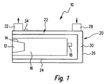
- a heater is generally designated 10.
- the heater 10 has one positioned and general in its inner area with 12 designated heat source in the form of a heating burner 14 a flame tube 16 associated therewith.
- the structure of such The heating burner is generally well known and is therefore not used here described in detail.
- the heat source 12 or the heating burner 14 is assigned a flame sensor, generally designated 18.
- this is a temperature sensor that measures the temperature in the outlet area of the flame tube 16 detected. The temperature therefore corresponds, for example approximately the temperature of the gases leaving the flame tube 16 and provides an indication of whether or to what extent in the flame tube 16 combustion takes place.
- the heat source 12 is surrounded by an at least partially double-walled Housing arrangement 20 which is essentially a heat exchanger area 22 forms.
- An inner housing wall 24 is the Heat source 12 is arranged and is substantially directly surrounding thus also in direct thermal contact with those from the flame tube 16 escaping combustion gases.
- a temperature sensor 34 is on the outside of the housing wall 26 intended. This temperature sensor 34 detects the temperature of the housing wall 26 in an area near the liquid outlet 32. This Temperature corresponds to some time delay in normal operation - due to the inertia in the heat transfer - with the Temperature of the liquid leaving the heating device 10.
- the heating burner 12 does heat up from the housing wall 24 transfer the liquid present in the area 30 because this liquid however, the heat does not come from the area of the heat exchanger area 22 dissipated. Even then there is a potential danger of Overheating.
- the present invention now provides measures with which alone by providing the temperature sensor 34 and the flame sensor or temperature sensor 18 can be detected whether overheating in the Area of the heating device 10, in particular in the area of the heat exchanger area 22 is present, although there is no direct contact with the thermal most heavily loaded area, i.e. the housing wall 24, is present, as is the case, for example, with the prior art is. This is also explained below with reference to FIG. 2.
- There different curves are shown for different operating states the change over time of the temperature sensors 18, 34 represent recorded temperatures. Curves a, b, c and d, which too the designation FF is assigned to show for various below operating states of the heating device specified even more precisely the temporal Gradients of the by the flame sensor or temperature sensor 18th recorded temperature.
- Curve a is assigned to an operating state, in which due to a leak or due to lack Filling in the heat exchanger area 22 there is no liquid.
- Curve b indicates the state in which it is in the heat exchanger area 22 liquid is present, but for example due to a Pump failure no flow is present.
- the curve c stands for the In case the system works correctly and the liquid with that in normal Operation minimal expected flow rate, i.e. the minimum Flow through which the heat exchanger region 22 passes.
- curve d represents the case in which also in the correct mode of operation the liquid the heat exchanger area 22 with the in operation maximum expected flow or maximum expected flow rate flows through.
- the curves labeled a ', b', c 'and d' show the corresponding ones Curves of the temperature gradient for the various operating states, as in the area of the temperature sensor designated T3 in FIG. 2 the outside of the outer housing wall 26 can be detected.
- T3 the area of the temperature sensor designated T3 in FIG. 2 the outside of the outer housing wall 26 can be detected.
- a hatched area through the curves c 'and d' B limits upwards and downwards, which area ultimately unites correct operating status reflected.
- correct operation with minimal Flow is compared with the temperature rise in the Area of the flame tube 16 expected time delay also due to the slowly flowing liquid in the area of the temperature sensor 34 or T3 a gradual increase in temperature or a gradual increase of the temperature gradient occur.
- Temperature sensor 18 detected a comparatively small course has a time delay.
- the reason for this is that in the area of the heat exchanger 22 standing liquid is a comparatively good heat conductor is and thus the housing wall 26 is heated quickly. is the system is not or not sufficiently filled with liquid, so in The area of the temperature sensor 34 likewise lies above the normal one Temperature rise can be detected, but with a clearer time Delay, as can be seen from curve a '. This delay is on it attributed to that then existing in the heat exchanger area 22 Air provides significantly better thermal insulation than non-circulating Liquid.
- the diagram in FIG. 2 shows that soon after the significant temperature rise in the area of the temperature sensor 18 also in the area of that provided on the outside of the housing wall 26 Temperature sensor 34 a swinging out of the temperature gradient from that through the two curves c 'and d' up and down limited permissible range B for the temperature gradient occurs in the area of the temperature sensor 34. From this realization the present invention makes use of the fact that initially by Observation of the temperature sensor or flame sensor 18 outputs Signal or the temporal gradient formed therefrom the operating state the heat source 12 or the heating burner 14 is determined.
- the Gradient evaluation can be recognized whether this gradient is still in the predetermined and permissible defined by the curves c 'and d' Range of values B lies or whether here, as can be seen from the curves a 'and b', there is a clear deviation.
- the temperature sensor 18 delivers with its output signal or the temperature gradient formed from it ultimately the trigger for evaluating the temperature gradient, which is generated from the signal of the temperature sensor 34. This interaction is particularly important because the Time at which combustion occurs after activation of the system occurs and thus also the temperatures in the range of the invention Device 10 change noticeably, greatly from the external circumstances, such as.
- the system according to the invention is regarding overheating detection thus insensitive to external influences.
- the present invention makes it possible without a temperature sensor directly to the thermally very strongly stressed components, for example, to bring up the inner housing wall 24 comparatively short time to recognize whether the system is working correctly, or whether there is a risk of overheating.
- it is according to The principles of the present invention also do not require a temperature sensor to immerse in the area 30.
- a temperature sensor to immerse in the area 30.
- the room area 30 flowing fluid then moves with approximately the same Remaining temperature at liquid outlet 32.
- the temperature is recorded by means of the temperature sensor 34 in the area of the liquid inlet 28, if necessary also when the temperature is on the outside of the housing wall 26 is detected, will therefore lead to a temperature profile, which corresponds qualitatively to the course shown in FIG. 2. It can thus also the procedure according to the invention for the evaluation be provided.
Landscapes
- Engineering & Computer Science (AREA)
- Physics & Mathematics (AREA)
- Thermal Sciences (AREA)
- Mechanical Engineering (AREA)
- Chemical & Material Sciences (AREA)
- Combustion & Propulsion (AREA)
- General Engineering & Computer Science (AREA)
- Control Of Combustion (AREA)
- Air-Conditioning For Vehicles (AREA)
- Domestic Hot-Water Supply Systems And Details Of Heating Systems (AREA)
Abstract
Description
- Fig. 1
- eine schematische Ansicht einer Heizeinrichtung mit Wärmetauscherbereich;
- Fig. 2
- den zeitlichen Verlauf verschiedener die Temperaturänderung in verschiedenen Systembereichen wiedergebender Größen.
Claims (13)
- Verfahren zur Überhitzungserkennung bei einer Heizeinrichtung, welche Heizeinrichtung umfasst:wobei das Verfahren die Schritte umfasst:eine Wärmequelle (12),eine den Betriebszustand der Wärmequelle sensierende erste Sensoranordnung (18),einen mit zu erwärmendem Fluid durchströmbaren Wärmetauscherbereich (22),eine zweite Sensoranordnung (34) zur Temperaturerfassung vorzugsweise im Bereich eines Fluidaustritts (32), an welchem Fluidaustritt (32) Fluid, das den Wärmetauscherbereich (22) durchströmt hat, zur Abgabe an ein zu erwärmendes System austritt,a) beruhend auf einer Sensorausgabe der ersten Sensoranordnung (18), Ermitteln einer den Betriebszustand der Wärmequelle (12) charakterisierenden ersten Größe,b) beruhend auf einer Sensorausgabe der zweiten Sensoranordnung (34), Ermitteln einer mit der Temperatur im Bereich der zweiten Sensoranordnung in Zusammenhang stehenden zweiten Größe,c) dann, wenn die erste Größe auf das Vorliegen eines vorbestimmten Betriebszustandes der Wärmequelle (12) hindeutet, Überprüfen, ob die zweite Größe in einem vorbestimmten Wertebereich (B) liegt,d) dann, wenn die zweite Größe nicht in dem vorbestimmten Wertebereich (B) liegt, Bestimmen, dass die Heizeinrichtung (10) in einem Überhitzungszustand ist.
- Verfahren nach Anspruch 1,
dadurch gekennzeichnet, dass die erste Sensoranordnung (18) einen Temperatursensor (18) zur Erfassung einer mit der Temperatur im Bereich der Wärmequelle (12) in Zusammenhang stehenden Größe umfasst und dass die erste Größe durch Bilden des zeitlichen Gradienten der Temperatur im Bereich der Wärmequelle (12) ermittelt wird. - Verfahren nach Anspruch 2,
dadurch gekennzeichnet, dass im Schritt c) auf Vorliegen des vorbestimmten Betriebszustandes dann entschieden wird, wenn der zeitliche Gradient der Temperatur im Bereich der Wärmequelle (12) einen vorbestimmten Schwellenwert überschreitet. - Verfahren nach Anspruch 2 oder 3,
dadurch gekennzeichnet, dass die Wärmequelle (12) einen Heizbrenner (14) umfasst und dass durch die erste Sensoranordnung (18) eine mit der Flammtemperatur des Heizbrenners (14) in Zusammenhang stehende Größe erfasst wird. - Verfahren nach einem der Ansprüche 1 bis 4,
dadurch gekennzeichnet, dass die zweite Größe durch Bilden des zeitlichen Gradienten der Temperatur im Bereich der zweiten Sensoranordnung (34) ermittelt wird. - Verfahren nach einem der Ansprüche 1 bis 5,
dadurch gekennzeichnet, dass der vorbestimmte Wertebereich (B) der zweiten Größe begrenzt ist durch einen bei Durchströmen des Wärmetauscherbereichs (22) mit Fluid mit einer im Betrieb minimal zu erwartenden Strömungsrate sich ergebenden Wert der zweiten Größe. - Verfahren nach einem der Ansprüche 1 bis 6,
dadurch gekennzeichnet, dass der vorbestimmte Wertebereich (B) der zweiten Größe begrenzt ist durch einen bei Durchströmen des Wärmetauscherbereichs (22) mit Fluid mit einer im Betrieb maximal zu erwartenden Strömungsrate sich ergebenden Wert der zweiten Größe. - Verfahren nach einem der Ansprüche 1 bis 7,
dadurch gekennzeichnet, dass der vorbestimmte Wertebereich mit fortschreitender Zeit verändert wird, vorzgsweise vergrößert wird. - Heizeinrichtung, umfassend:eine Wärmequelle (12),eine den Betriebszustand der Wärmequelle (12) sensierende erste Sensoranordnung (18),einen mit zu erwärmendem Fluid durchströmbaren Wärmetauscherbereich (22),eine zweite Sensoranordnung (34) zur Temperaturerfassung vorzugsweise im Bereich eines Fluidaustritts (32), an welchem Fluidaustritt (32) Fluid, das den Wärmetauscherbereich (34) durchströmt hat, zur Abgabe an ein zu erwärmendes System austritt,eineÜberhitzungsüberwachungseinheit,welchedazuausgebildet ist, dann, wenn die Wärmequelle (12) in einem vorbestimmten Betriebszustand ist, durch Vergleich einer mit der Temperatur im Bereich der zweiten Sensoranordnung (34) in Zusammenhang stehenden Größe mit einem vorbestimmten Wertebereich (B) für diese Größe zu erkennen, ob die Heizeinrichtung (10) in einem Überhitzungszustand ist.
- Heizeinrichtung nach Anspruch 9,
dadurch gekennzeichnet, dass die Wärmequelle (12) einen Heizbrenner (14) umfasst und dass die erste Sensoranordnung (18) einen Sensor (18) zur Erfassung einer mit einer Flammtemperatur des Heizbrenners (14) in Zusammenhang stehenden Größe umfasst. - Heizeinrichtung nach Anspruch 9 oder 10,
dadurch gekennzeichnet, dass die zweite Sensoranordnung (34) einen Temperatursensor (34) umfasst, welcher nicht in direktem Wärmeerfassungskontakt mit einem die Wärmequelle umschließenden Gehäusebereich (26) des Wärmetauscherbereichs (22) steht. - Heinzeinrichtung nach Anspruch 11,
dadurch gekennzeichnet, dass der Temperatursensor (34) der zweiten Sensoranordnung (34) die Temperatur eines den Wärmetauscherbereich (22) an der von der Wärmequelle (12) abgewandten Seite umschließenden Gehäusebereichs (26) erfasst. - Heizeinrichtung nach Anspruch 11 oder 12,
dadurch gekennzeichnet, dass der Temperatursensor (34) der zweiten Sensoranordnung (34) außerhalb des von dem den Wärmetauscherbereich (22) durchstömenden Fluid durchströmten Volumenbereichs des Wärmetauscherbereichs (22) angeordnet ist.
Applications Claiming Priority (2)
| Application Number | Priority Date | Filing Date | Title |
|---|---|---|---|
| DE10130810A DE10130810A1 (de) | 2001-06-26 | 2001-06-26 | Verfahren zur Überhitzungserkennung bei einer Heizeinrichtung |
| DE10130810 | 2001-06-26 |
Publications (3)
| Publication Number | Publication Date |
|---|---|
| EP1275911A2 true EP1275911A2 (de) | 2003-01-15 |
| EP1275911A3 EP1275911A3 (de) | 2004-08-18 |
| EP1275911B1 EP1275911B1 (de) | 2012-10-17 |
Family
ID=7689521
Family Applications (1)
| Application Number | Title | Priority Date | Filing Date |
|---|---|---|---|
| EP02014271A Expired - Lifetime EP1275911B1 (de) | 2001-06-26 | 2002-06-26 | Verfahren zur Überhitzungserkennung bei einer Heizeinrichtung |
Country Status (4)
| Country | Link |
|---|---|
| EP (1) | EP1275911B1 (de) |
| JP (1) | JP2003011650A (de) |
| CZ (1) | CZ295610B6 (de) |
| DE (1) | DE10130810A1 (de) |
Citations (1)
| Publication number | Priority date | Publication date | Assignee | Title |
|---|---|---|---|---|
| DE4446829A1 (de) | 1993-12-31 | 1995-07-06 | Eberspaecher J | Fahrzeugheizgerät mit Überhitzungs-Überwachungseinrichtung |
Family Cites Families (5)
| Publication number | Priority date | Publication date | Assignee | Title |
|---|---|---|---|---|
| DE3517954A1 (de) * | 1985-05-18 | 1986-11-20 | Webasto-Werk W. Baier GmbH & Co, 8035 Gauting | Heizgeraet |
| DE3839244C2 (de) * | 1988-02-24 | 1993-12-09 | Webasto Ag Fahrzeugtechnik | Heizgerät, insbesondere Fahrzeugzusatzheizgerät |
| DE19524260C5 (de) * | 1995-07-04 | 2005-11-17 | J. Eberspächer GmbH & Co. KG | Heizgerät, insbesondere zur Innenraumbeheizung eines Kraftfahrzeuges |
| DE19605323C1 (de) * | 1996-02-14 | 1997-02-27 | Webasto Thermosysteme Gmbh | Verfahren zum Betreiben eines Fahrzeugzusatzheizgerätes |
| EP0892215B1 (de) * | 1997-07-18 | 2002-11-20 | WEBASTO THERMOSYSTEME GmbH | Verfahren zum Steuern eines Überhitzungsschutzes für ein Heizgerät |
-
2001
- 2001-06-26 DE DE10130810A patent/DE10130810A1/de not_active Withdrawn
-
2002
- 2002-06-24 CZ CZ20022217A patent/CZ295610B6/cs not_active IP Right Cessation
- 2002-06-26 EP EP02014271A patent/EP1275911B1/de not_active Expired - Lifetime
- 2002-06-26 JP JP2002186485A patent/JP2003011650A/ja active Pending
Patent Citations (1)
| Publication number | Priority date | Publication date | Assignee | Title |
|---|---|---|---|---|
| DE4446829A1 (de) | 1993-12-31 | 1995-07-06 | Eberspaecher J | Fahrzeugheizgerät mit Überhitzungs-Überwachungseinrichtung |
Also Published As
| Publication number | Publication date |
|---|---|
| EP1275911A3 (de) | 2004-08-18 |
| DE10130810A1 (de) | 2003-01-09 |
| CZ295610B6 (cs) | 2005-08-17 |
| CZ20022217A3 (cs) | 2003-02-12 |
| EP1275911B1 (de) | 2012-10-17 |
| JP2003011650A (ja) | 2003-01-15 |
Similar Documents
| Publication | Publication Date | Title |
|---|---|---|
| DE4446829B4 (de) | Fahrzeugheizgerät mit Überhitzungs-Überwachungseinrichtung | |
| EP2260361B1 (de) | Vorrichtung und verfahren zum überwachen von beheizten flüssigkeitsbädern | |
| DE3018682C2 (de) | ||
| DE102009051931B4 (de) | Verfahren und Vorrichtung zur Früherkennung von Fluidleckagen in einer Stranggießanlage oder in einem Hochofen | |
| DE19948249A1 (de) | Kühlsystem für eine Brennkraftmaschine in Kraftfahrzeugen | |
| WO1997002516A1 (de) | Heizgerät, insbesondere zur innenraumbeheizung eines kraftfahrzeuges | |
| EP3037741A1 (de) | Verfahren zur vermeidung von trockenbrand bei elektrischen durchlauferhitzern | |
| DE60003901T2 (de) | Fahrzeug | |
| DE3544024C2 (de) | ||
| EP1275911B1 (de) | Verfahren zur Überhitzungserkennung bei einer Heizeinrichtung | |
| DE102008038733A1 (de) | Verfahren zur Vermeidung von Überhitzungsschäden an einer thermischen Solaranlage | |
| EP0433215B1 (de) | Verfahren und Vorrichtung zum Überwachen des Heizwasserumlaufs bei einem Gaswasserheizer | |
| DE4433632A1 (de) | Verfahren zur Überwachung einer Heizeinrichtung eines im Abgassystem einer Brennkraftmaschine angebrachten Sensors | |
| DE102012220526B3 (de) | Verfahren zur Flammabbrucherkennung bei einem brennstoffbetriebenen Heizgerät, insbesondere Fahrzeugheizgerät | |
| DE10133826A1 (de) | Verfahren und Vorrichtung zur Prüfung der Funktionsfähigkeit eines Behältnisses, insbesondere einer Tankanlage | |
| DE10138821B4 (de) | Verfahren zum Ermitteln einer Heizluft-Ausblastemperatur eines Luftheizgerätes | |
| EP1837730B1 (de) | Heizgerät mit Überhitzungsschutz und Verfahren zum Bereitstellen eines für den Überhitzungsschutz verwertbaren Signals | |
| DE102013008743B3 (de) | Verfahren zur Steuerung eines Kühlmittelflusses in einem Kraftfahrzeug und Kraftfahrzeug | |
| DE19718407C2 (de) | Brennstoffbetriebenes Heizgerät, insbesondere motorunabhängig betriebenes Luftheizgerät für Kraftfahrzeuge | |
| DE69614230T2 (de) | Verbrennungssteueranlage | |
| DE19645179A1 (de) | Heizgerät mit Temperatursicherungseinrichtung | |
| EP1275537B1 (de) | Verfahren zum Betreiben einer Heizeinrichtung und Heizeinrichtung | |
| DE2319733C3 (de) | Regelsystem zur Aufrechterhaltung der mittleren Temperatur in einer Ersatzlast | |
| WO2018060419A1 (de) | Vorrichtung zum beeinflussen des volumenstroms eines füllprodukts in einer abfüllanlage | |
| EP2280230B1 (de) | Verfahren zur Überwachung des Verschmutzungszustandes eines Wärmetauschers an einem Heizgerät |
Legal Events
| Date | Code | Title | Description |
|---|---|---|---|
| PUAI | Public reference made under article 153(3) epc to a published international application that has entered the european phase |
Free format text: ORIGINAL CODE: 0009012 |
|
| AK | Designated contracting states |
Kind code of ref document: A2 Designated state(s): AT BE CH CY DE DK ES FI FR GB GR IE IT LI LU MC NL PT SE TR |
|
| AX | Request for extension of the european patent |
Free format text: AL;LT;LV;MK;RO;SI |
|
| PUAL | Search report despatched |
Free format text: ORIGINAL CODE: 0009013 |
|
| AK | Designated contracting states |
Kind code of ref document: A3 Designated state(s): AT BE CH CY DE DK ES FI FR GB GR IE IT LI LU MC NL PT SE TR |
|
| AX | Request for extension of the european patent |
Extension state: AL LT LV MK RO SI |
|
| RIC1 | Information provided on ipc code assigned before grant |
Ipc: 7B 60H 1/22 B Ipc: 7F 23N 5/24 B Ipc: 7F 24H 9/20 A |
|
| 17P | Request for examination filed |
Effective date: 20040906 |
|
| AKX | Designation fees paid |
Designated state(s): DE FR GB SE |
|
| RBV | Designated contracting states (corrected) |
Designated state(s): DE FR GB SE |
|
| GRAP | Despatch of communication of intention to grant a patent |
Free format text: ORIGINAL CODE: EPIDOSNIGR1 |
|
| GRAS | Grant fee paid |
Free format text: ORIGINAL CODE: EPIDOSNIGR3 |
|
| GRAA | (expected) grant |
Free format text: ORIGINAL CODE: 0009210 |
|
| AK | Designated contracting states |
Kind code of ref document: B1 Designated state(s): DE FR GB SE |
|
| REG | Reference to a national code |
Ref country code: GB Ref legal event code: FG4D Free format text: NOT ENGLISH |
|
| REG | Reference to a national code |
Ref country code: DE Ref legal event code: R096 Ref document number: 50215630 Country of ref document: DE Effective date: 20121213 |
|
| REG | Reference to a national code |
Ref country code: SE Ref legal event code: TRGR |
|
| REG | Reference to a national code |
Ref country code: DE Ref legal event code: R082 Ref document number: 50215630 Country of ref document: DE Representative=s name: WEICKMANN & WEICKMANN, DE |
|
| RAP2 | Party data changed (patent owner data changed or rights of a patent transferred) |
Owner name: EBERSPAECHER CLIMATE CONTROL SYSTEMS GMBH & CO. KG |
|
| PGFP | Annual fee paid to national office [announced via postgrant information from national office to epo] |
Ref country code: SE Payment date: 20130620 Year of fee payment: 12 Ref country code: GB Payment date: 20130620 Year of fee payment: 12 |
|
| REG | Reference to a national code |
Ref country code: DE Ref legal event code: R081 Ref document number: 50215630 Country of ref document: DE Owner name: EBERSPAECHER CLIMATE CONTROL SYSTEMS GMBH & CO, DE Free format text: FORMER OWNER: J. EBERSPAECHER GMBH & CO. KG, 73730 ESSLINGEN, DE Effective date: 20130607 Ref country code: DE Ref legal event code: R081 Ref document number: 50215630 Country of ref document: DE Owner name: EBERSPAECHER CLIMATE CONTROL SYSTEMS GMBH & CO, DE Free format text: FORMER OWNER: J. EBERSPAECHER GMBH & CO. KG, 73730 ESSLINGEN, DE Effective date: 20121017 Ref country code: DE Ref legal event code: R082 Ref document number: 50215630 Country of ref document: DE Representative=s name: WEICKMANN & WEICKMANN, DE Effective date: 20130607 Ref country code: DE Ref legal event code: R082 Ref document number: 50215630 Country of ref document: DE Representative=s name: RUTTENSPERGER LACHNIT TROSSIN GOMOLL PATENT- U, DE Effective date: 20130607 Ref country code: DE Ref legal event code: R082 Ref document number: 50215630 Country of ref document: DE Representative=s name: RUTTENSPERGER LACHNIT TROSSIN GOMOLL, PATENT- , DE Effective date: 20130607 |
|
| PLBE | No opposition filed within time limit |
Free format text: ORIGINAL CODE: 0009261 |
|
| STAA | Information on the status of an ep patent application or granted ep patent |
Free format text: STATUS: NO OPPOSITION FILED WITHIN TIME LIMIT |
|
| PGFP | Annual fee paid to national office [announced via postgrant information from national office to epo] |
Ref country code: FR Payment date: 20130703 Year of fee payment: 12 |
|
| REG | Reference to a national code |
Ref country code: FR Ref legal event code: CD Owner name: EBERSPAECHER CLIMATE CONTROL SYSTEMS GMBH & CO., D Effective date: 20130807 |
|
| 26N | No opposition filed |
Effective date: 20130718 |
|
| REG | Reference to a national code |
Ref country code: DE Ref legal event code: R097 Ref document number: 50215630 Country of ref document: DE Effective date: 20130718 |
|
| REG | Reference to a national code |
Ref country code: DE Ref legal event code: R082 Ref document number: 50215630 Country of ref document: DE Representative=s name: RUTTENSPERGER LACHNIT TROSSIN GOMOLL PATENT- U, DE Ref country code: DE Ref legal event code: R082 Ref document number: 50215630 Country of ref document: DE Representative=s name: RUTTENSPERGER LACHNIT TROSSIN GOMOLL, PATENT- , DE |
|
| PG25 | Lapsed in a contracting state [announced via postgrant information from national office to epo] |
Ref country code: SE Free format text: LAPSE BECAUSE OF NON-PAYMENT OF DUE FEES Effective date: 20140627 |
|
| REG | Reference to a national code |
Ref country code: SE Ref legal event code: EUG |
|
| GBPC | Gb: european patent ceased through non-payment of renewal fee |
Effective date: 20140626 |
|
| REG | Reference to a national code |
Ref country code: FR Ref legal event code: ST Effective date: 20150227 |
|
| PG25 | Lapsed in a contracting state [announced via postgrant information from national office to epo] |
Ref country code: FR Free format text: LAPSE BECAUSE OF NON-PAYMENT OF DUE FEES Effective date: 20140630 Ref country code: GB Free format text: LAPSE BECAUSE OF NON-PAYMENT OF DUE FEES Effective date: 20140626 |
|
| PGFP | Annual fee paid to national office [announced via postgrant information from national office to epo] |
Ref country code: DE Payment date: 20150630 Year of fee payment: 14 |
|
| REG | Reference to a national code |
Ref country code: DE Ref legal event code: R119 Ref document number: 50215630 Country of ref document: DE |
|
| PG25 | Lapsed in a contracting state [announced via postgrant information from national office to epo] |
Ref country code: DE Free format text: LAPSE BECAUSE OF NON-PAYMENT OF DUE FEES Effective date: 20170103 |