EP1275881A2 - Toroidal continuously-variable transmission - Google Patents
Toroidal continuously-variable transmission Download PDFInfo
- Publication number
- EP1275881A2 EP1275881A2 EP02015015A EP02015015A EP1275881A2 EP 1275881 A2 EP1275881 A2 EP 1275881A2 EP 02015015 A EP02015015 A EP 02015015A EP 02015015 A EP02015015 A EP 02015015A EP 1275881 A2 EP1275881 A2 EP 1275881A2
- Authority
- EP
- European Patent Office
- Prior art keywords
- trunnion
- link
- stopper
- side stopper
- tilt rotation
- Prior art date
- Legal status (The legal status is an assumption and is not a legal conclusion. Google has not performed a legal analysis and makes no representation as to the accuracy of the status listed.)
- Granted
Links
- 230000005540 biological transmission Effects 0.000 title claims abstract description 80
- 238000005096 rolling process Methods 0.000 claims abstract description 4
- 230000003247 decreasing effect Effects 0.000 claims description 7
- 230000000694 effects Effects 0.000 description 44
- 238000004519 manufacturing process Methods 0.000 description 7
- 230000012447 hatching Effects 0.000 description 4
- 238000003754 machining Methods 0.000 description 4
- 238000000034 method Methods 0.000 description 4
- 238000005242 forging Methods 0.000 description 3
- 238000005245 sintering Methods 0.000 description 3
- 238000005516 engineering process Methods 0.000 description 2
- 238000005266 casting Methods 0.000 description 1
- 238000010276 construction Methods 0.000 description 1
- 230000008030 elimination Effects 0.000 description 1
- 238000003379 elimination reaction Methods 0.000 description 1
- 238000003780 insertion Methods 0.000 description 1
- 230000037431 insertion Effects 0.000 description 1
- 238000012986 modification Methods 0.000 description 1
- 230000004048 modification Effects 0.000 description 1
- 125000006850 spacer group Chemical group 0.000 description 1
Images







Classifications
-
- F—MECHANICAL ENGINEERING; LIGHTING; HEATING; WEAPONS; BLASTING
- F16—ENGINEERING ELEMENTS AND UNITS; GENERAL MEASURES FOR PRODUCING AND MAINTAINING EFFECTIVE FUNCTIONING OF MACHINES OR INSTALLATIONS; THERMAL INSULATION IN GENERAL
- F16H—GEARING
- F16H15/00—Gearings for conveying rotary motion with variable gear ratio, or for reversing rotary motion, by friction between rotary members
- F16H15/02—Gearings for conveying rotary motion with variable gear ratio, or for reversing rotary motion, by friction between rotary members without members having orbital motion
- F16H15/04—Gearings providing a continuous range of gear ratios
- F16H15/06—Gearings providing a continuous range of gear ratios in which a member A of uniform effective diameter mounted on a shaft may co-operate with different parts of a member B
- F16H15/32—Gearings providing a continuous range of gear ratios in which a member A of uniform effective diameter mounted on a shaft may co-operate with different parts of a member B in which the member B has a curved friction surface formed as a surface of a body of revolution generated by a curve which is neither a circular arc centered on its axis of revolution nor a straight line
- F16H15/36—Gearings providing a continuous range of gear ratios in which a member A of uniform effective diameter mounted on a shaft may co-operate with different parts of a member B in which the member B has a curved friction surface formed as a surface of a body of revolution generated by a curve which is neither a circular arc centered on its axis of revolution nor a straight line with concave friction surface, e.g. a hollow toroid surface
- F16H15/38—Gearings providing a continuous range of gear ratios in which a member A of uniform effective diameter mounted on a shaft may co-operate with different parts of a member B in which the member B has a curved friction surface formed as a surface of a body of revolution generated by a curve which is neither a circular arc centered on its axis of revolution nor a straight line with concave friction surface, e.g. a hollow toroid surface with two members B having hollow toroid surfaces opposite to each other, the member or members A being adjustably mounted between the surfaces
Definitions
- the present invention relates to a toroidal continuously-variable transmission for a vehicle, and more specifically to technique for limiting rotation of trunnions.
- a Published Japanese Patent Application Publication No. H06(1994)-34007 shows a stopper structure, formed on a lower link, for limiting the movement of a trunnion.
- a Published Japanese Patent Application Publication No. H07(1995)-332450 shows a tilt rotation synchronizing wire connecting left and right trunnions.
- a toroidal continuously-variable transmission comprises: input and output disks defining a toroidal cavity; a first power roller pressed in the toroidal cavity between the input and output disks for transmission of torque; a first trunnion supporting the first power roller; a first link supporting a first end of the first trunnion; a second link supporting a second end of the first trunnion through a bearing; an axial movement limiting member to limit axial movement of the bearing in an axial direction of the first trunnion; a first tilt rotation synchronizing wire connecting the first trunnion with a second trunnion supporting a second power roller interposed between the input and output disks; and a tilt rotation stopper structure to limit a range of rotation of the first trunnion so as to prevent contact points of the first power roller with the input and output disks from deviating from respective rolling contact surfaces, the tilt rotation stopper structure including, a link-
- a toroidal-continuously-variable transmission comprises: axial movement limiting means for limiting axial movement of the bearing in an axial direction of the first trunnion on a second side of the second link; and rotation limiting means for limiting rotation of the first trunnion on the second side of the second link.
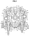
- FIG. 1 is a sectional view showing a toroidal continuously-variable transmission according to a first embodiment of the present invention.
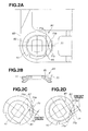
- FIGS. 2A, 2B, 2C and 2D are views showing a tilt rotation stopper structure A1 in the toroidal continuously-variable transmission of FIG. 1.
- FIG. 3 is a sectional view showing a half of a toroidal continuously-variable transmission according to a second embodiment of the present invention.
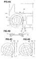
- FIGS. 4A, 4B, 4C and 4D are views showing a tilt rotation stopper structure A2 in the toroidal continuously-variable transmission of FIG. 3.
- FIG. 5 is a sectional view showing a half of a toroidal continuously-variable transmission according to a third embodiment of the present invention.
- FIGS. 6A, 6B, 6C and 6D are views showing a tilt rotation stopper structure A3 in the toroidal continuously-variable transmission of FIG. 5.
- FIGS. 7A, 7B and 7C are views showing a tilt rotation stopper structure A4 according to a fourth embodiment of the invention.
- FIG. 8 is a sectional view showing a half of a toroidal continuously-variable transmission according to a fifth embodiment of the present invention.
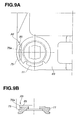
- FIGS. 9A and 9B are views showing a tilt rotation stopper structure A5 in the toroidal continuously-variable transmission of FIG. 8.
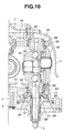
- FIG. 10 is a sectional view showing a half of a toroidal continuously-variable transmission according to a sixth embodiment of the present invention.
- FIGS. 11A, 11B and 11C are views showing a tilt rotation stopper structure A6 in the toroidal continuously-variable transmission of FIG. 10.
- FIG. 12 is a sectional view showing a toroidal continuously-variable transmission according to a seventh embodiment of the present invention.
- FIGS. 13A, 13B, 13C and 13D are views showing a tilt rotation stopper structure A7 (A7') in the toroidal continuously-variable transmission of FIG. 12.
- FIG. 14 is a sectional view showing a half of a toroidal continuously-variable transmission according to an eighth embodiment of the present invention.
- FIG. 15 is a view showing a tilt rotation stopper structure A8 in the toroidal continuously-variable transmission of FIG. 14.
- FIG. 16 is a view showing a tilt rotation stopper structure A9 according to a ninth embodiment of the present invention.
- FIG. 17 is a view showing a tilt rotation stopper structure A10 according to a tenth embodiment of the present invention.
- FIG. 18 is a sectional view showing a half of a toroidal continuously-variable transmission according to an eleventh embodiment of the present invention.
- FIG. 19 is a view showing a tilt rotation stopper structure A11 in the toroidal continuously-variable transmission of FIG. 18.
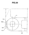
- FIG. 20 is a view showing a tilt rotation stopper structure A12 according to a twelfth embodiment of the present invention.
- FIG. 21 is a view showing a tilt rotation stopper structure A13 according to a thirteenth embodiment of the present invention.
- FIG. 22 is a sectional view showing a half of a toroidal continuously-variable transmission according to an fourteenth embodiment of the present invention.
- FIG. 23 is a sectional view showing a half of a toroidal continuously-variable transmission according to a fifteenth embodiment of the present invention.
- FIG. 24 is a view showing tilt rotation synchronizing wires in a dual-cavity toroidal continuously-variable transmission of related art.
- FIGS. 1 and 2A-2D show a toroidal continuously-variable transmission according to a first embodiment of the present invention.
- the toroidal CVT transmission of FIG. 1 includes transmission case 1, upper link post 2, lower link post 3, lower cover 4, upper washers 10, lower washers 11 (axial movement limiting members), spacers 12, output disk 44, power rollers 45, left and right tilt rotation synchronizing wire 57, front and rear tilt rotation synchronizing wire 58, trunnions 59, trunnion shafts 60, servo pistons 61, upper link 62, lower link 63, bearing outer races 64, trunnion holes 65, radial needle bearings 66 and tilt rotation stopper structures A1.
- the toroidal CVT transmission is a dual-cavity type including a first (front) CVT unit having a first input disk and a first output disk, and a second (rear) CVT unit having a second input disk and a second output disk.
- the first and second output disks are placed axially between the first and second input disks.
- Left and right (or first and second) power rollers 45 are pressed between the input and output disks of each of the first and second CVT units.
- the following explanation is mainly directed to only one of the first and second CVT units since the first and second CVT units are substantially identical in construction, and arranged symmetrically so that one is substantially an mirror image of the other.
- Each power roller 45 is supported by trunnion 59 which is rotatable about a tilt rotation axis (or swing axis) L perpendicular to a power roller rotation axis.
- trunnion 59 which is rotatable about a tilt rotation axis (or swing axis) L perpendicular to a power roller rotation axis.
- left and right trunnions 59 supporting the left and right power rollers 45, respectively, in each of the first and second CVT units.
- Upper link 62 is supported swingably by upper link post 2.
- Upper link 62 has four trunnion holes 65 opened, respectively, in four corners of upper link 62.
- Each hole 65 of upper link 62 supports the upper end of the corresponding trunnion 59 rotatably through a spherical bearing composed of bearing outer race 64 and radial needle bearing 66, so as to position the upper trunnion end and to permit tilting rotation.
- Lower link 63 is supported swingably by lower link post 3.
- Lower link 63 has four trunnion holes 65 opened, respectively, in four corners of lower link 63.
- Each hole 65 of lower link 63 supports the lower end of the corresponding trunnion 59 rotatably through a spherical bearing composed of bearing outer race 64 and radial needle bearing 66, so as to position the upper trunnion end and to permit tilting rotation.
- Lower washer 11 is provided for each trunnion 59, and arranged to limit axial movement of the spherical bearing (bearing outer race 64 and radial needle bearing 66) provided between the corresponding trunnion 59 and lower link 63, in the axial direction of tilt rotation axis L.
- Lower washer 11 rotates as a unit with the corresponding trunnion 59 and its trunnion shaft 60.
- Lower washer 11 limits the relative position between trunnion 59 and lower link 63 in the tilt rotation axis L.
- lower washer 11 of this example has an outer rim portion serving as a pulley for the front and rear synchronizing wire 58.
- Left and right rotation synchronizing wire 57 is stretched in the form of 8-shaped curve, between left and right trunnions 59 in each CVT unit.
- left and right synchronizing wire 57 is positioned above lower link 63.
- Left and right synchronizing wire 57 is located between lower link 63 and power rollers 45.
- Front and rear rotation synchronizing wire 58 is stretched in the form of 8-shaped curve between front and rear lower washers 11, to synchronize the tilt rotation between front and rear trunnions 59 of the front and rear CVT units.
- Tilt rotation stopper structure A1 in this example is provided for each trunnion 59.
- tilt rotation stopper structure A1 is provided on a link having left and right synchronizing wire 57, as distinguished from a link having no left and right synchronizing wire.
- the link having left and right synchronizing wire 57 is lower link 63
- the link having no left and right synchronizing wire is upper link 62. Therefore, tilt rotation stopper structure A1 is provided on lower link 63.
- Tilt rotation stopper structure A1 is designed to limit the range of tilt rotation of trunnion 59 so as to prevent the contact point of power roller 45 with each of input and output disks from deviating from the rolling contact surface.
- Tilt rotation stopper structure A1 is formed under lower link 63, and composed of a link-side stopper projection 71 (link-side stopper) and a trunnion-side stopper surface 81 (trunnion-side stopper), as shown in FIGS. 2A ⁇ 2D.
- Lower link 63 is placed between left and right synchronizing wire 57 on the upper side as viewed in FIG. 1, and tilt rotation stopper structure A1 on the lower side of lower link 63.
- Lower washer 11 is also located on the lower side of lower link 63.
- Link-side stopper projection 71 is formed in a lower link surface of lower link 63 facing downward as viewed in FIG. 1.
- Trunnion-side stopper surface 81 is formed in a side surface of lower washer 11.
- Link-side stopper projection 71 has a middle surface 71a and slant contact surfaces 71b and 71c, as shown in FIG. 2A.
- Middle surface 71a is substantially flat and parallel to trunnion-side stopper surface 81 when trunnion 59 is in the angular position for a speed ratio of one, as shown in FIGS. 2A and 2B.
- Middle surface 71a is located between slant contact surfaces 71b and 71c.
- link-side stopper projection 71 is shaped like an isosceles trapezoid having two parallel sides and non-parallel equal sides. Slant contact surfaces 71b and 71c define the non-parallel sides of the trapezoid, and middle surface 71b defines the shorter side parallel to the base of the trapezoid.
- Trunnion-side stopper surface 81 of lower washer 11 is a flat surface including a first flat region for contacting with slant contact surface 71b of link-side stopper projection 71 as shown in FIG. 2C when trunnion 59 is at a maximum speed increase position for maximum speed increase, and a second flat region for contacting with slant contact surface 71c of link-side stopper projection 71 as shown in FIG. 2D when trunnion 59 is at a maximum speed decrease position for maximum speed reduction.
- First and second flat regions are flush with each other.
- Toroidal CVT transmission can vary the speed ratio by moving each trunnion 59 in the direction of tilt rotation axis L, and thereby tilting the corresponding power roller 45.
- Trunnion 59 is moved in the direction of tilt rotation axis L by servo piston 61 when a stepper motor shifts a shift sleeve under a drive command representing a target speed ratio from a CVT controller, and hence operating oil is supplied to one chamber of servo piston 61 and drained from the other chamber.
- This movement of trunnion 59 functions to offset the axis of rotation of power roller 45 from the axis of rotation of disk. Consequently, side slipping forces are produced at the contact points of power roller 45 with input and output disks because of this offset, and power roller 45 tilts by the thus-produced side slipping forces.
- This tilting movement of power roller 45 and the offset are transmitted through a precess cam (or precision cam) and a lever, to a shift spool, and the shift movement ends when a balance is reached with the shift sleeve shifted by the stepper motor.
- a predetermined tilt angle is reached, trunnion 59 is returned so that the rotation center of power roller is returned to the original position coincident with the rotation center of disk, and the tilt operation of power roller 45 is ended.
- the speed ratio is determined by the tilt angle of power rollers 45.
- the transmission ratio or speed ratio is thus varied continuously when the ratio of the radius of rotation to the contact point of input disk to the radius of ration to the contact point of output disk is varied.
- the toroidal CVT transmission is equipped with the tilt rotation stopper structure A1 to limit the tilt rotation of trunnion on the speed increasing side and the speed decreasing side.
- trunnion 59 rotates in the clockwise direction as shown in FIG. 2C, and stopper surface 81 formed in lower washer 11 rotating with trunnion 59 abuts against slant contact surface 71b of link-side stopper projection 71 formed in lower link 63 as shown in FIG. 2C when the amount of rotational movement reaches the maximum. Slant contact surface 71b of link-side stopper projection 71 limits the further tilt rotation of trunnion 59.
- trunnion 59 rotates in the counterclockwise direction as shown in FIG.
- Tilt rotation stopper structure A1 utilizing axial movement limiting member is advantageous in the following points.
- Tilt rotation stopper structure A1 of the first embodiment can reduce the vertical dimension or height of the toroidal CVT transmission.
- This stopper structure A1 eliminates the need for arranging left and right synchronizing wire, tilt rotation stopper structure and axial movement limiting member in the axial direction of trunnion.
- tilt rotation stopper structure A1 is formed at the same level of lower washer 11 (axial movement limiting member).
- Link-side stopper 71 is provided on a first (lower) side of lower link 63 whereas left and right tilt rotation synchronizing wire 57 is provided on a second (upper) side of lower link 63 opposite to the first side.
- the first side is the side where left and right tilt rotation synchronizing wire 57 does not exist. This arrangement can prevent interference between link-side stopper 71 and left and right tilt rotation synchronizing wire 57.
- link-side stopper projection 71 can be made strong enough to stop the tilt rotation of trunnion 59 since link-side stopper projection 71 need not be formed inside the left and right tilt rotation synchronizing wire 57 stretched in the form of digit 8.
- Tilt rotation stopper structure provided on lower link 63 is advantageous in the following points.
- tilt rotation stopper structure A1 on lower link 63 increases the degree of freedom in design of upper link 62. With this arrangement, therefore, it is possible to decrease the height of the transmission and to facilitate the installment in a vehicle.
- upper link 62 is swingable about upper link post 2 to a predetermined angular range, and trunnions 59 cannot move out of respective trunnion holes 65 of upper link 62.
- upper link 62 is supported on the upper ends of left and right trunnions 59.
- upper washer 10' needs to be made larger in diameter at least partially than trunnion hole 65, and to be arranged to restrict the relative position of trunnion 59 and upper link 62 to prevent trunnion 59 from being removed from upper link 62.
- trunnion holes 65 needs to be made into the form of an elongate hole or a non-circular hole.
- the elongate or noncircular hole design makes it difficult to provide the tilt rotation stopper structure in upper link 62, and hence it becomes difficult to eliminate upper link post 2 and to reduce the overall height of the transmission.
- tilt rotation stopper structure A1 on lower link 63 makes it possible to employ the elongate or noncircular hole design for trunnion holes in upper link 62, and to eliminate upper link post 2 to reduce the transmission height.
- the elimination of upper link post 2 can eliminate the need for opening a hole for receiving upper link post 2 in upper link 62, and thereby reduce the manufacturing cost, and to improve the strength or rigidity of upper link 62.
- the toroidal CVT transmission is of the double-cavity type, and lower washer 11 combines the function of limiting the axial movement, the function of stopper and the function of pulley for carrying front and rear tilt rotation synchronizing wire 58 between front and rear trunnions.
- the first embodiment can provide the following effects.
- tilt rotation stopper structure A1 is formed at a position separated from left and right tilt rotation synchronizing wire 57. This arrangement is effective in preventing interference with left and right tilt rotation synchronizing wire 57, making the stopper structure strong enough to stop the rotation of trunnion 59, and reducing the vertical dimension of the transmission.
- tilt rotation stopper structure A1 is located at the side of lower link 63 which is provided with left and right tilt rotation synchronizing wire 57.
- tilt rotation stopper structure A1 is separated from left and right tilt rotation synchronizing wire 57 by second link 63. Therefore, the effect (1) can be achieved by a compact arrangement.
- Lower washer 11 combines the function of tilt rotation stopper and the function of a pulley for front and rear tilt synchronizing wire 58. Therefore, the first embodiment can decrease the number of required component parts. Stopper surface 81 of trunnion-side stopper can be readily made at the step of producing lower washer 11 by machining, lost wax process, or sintering. Therefore, this arrangement helps reduce the manufacturing cost.
- Tilt rotation stopper structure A1 is formed on the inner side of trunnion 59 on which there is output disk 44. Therefore, effective use can be made of the inner space.
- the single flat stopper surface 81 of trunnion-side stopper can facilitate the reduction of manufacturing cost.
- FIG. 3 shows a toroidal continuously-variable transmission according to a second embodiment of the present invention
- FIGS. 4A-4D show a tilt rotation stopper structure A2 according to the second embodiment.
- the toroidal continuously-variable transmission of FIG. 3 is substantially identical to that of FIG. 1.
- Tilt rotation stopper structure A2 of the second embodiment is different from tilt rotation stopper structure A1 of the first embodiment, in the following points.
- tilt rotation stopper structure A2 is provided on the lower side of lower link 63 having left and right synchronizing wire 57 on the upper side as in the first embodiment.
- Tilt rotation stopper structure A2 is composed of a link-side stopper projection 72 (link-side stopper) and a trunnion-side stopper surface 82 (trunnion-side stopper), as shown in FIGS. 4A ⁇ 4D.
- Lower link 63 is placed between left and right synchronizing wire 57 on the upper side as viewed in FIG. 3, and tilt rotation stopper structure A2 on the lower side of lower link 63.
- Lower washer 11 is also located on the lower side of lower link 63.
- Link-side stopper projection 72 is formed in the lower link surface of lower link 63 facing downward as viewed in FIG. 3.
- Trunnion-side stopper surface 82 is formed in the side surface of lower washer 11.
- Link-side stopper projection 72 has a single continuous flat surface 72a including a first flat region for contacting with trunnion-side stopper surface 82 as shown in FIG. 4C when trunnion 59 is at the maximum speed increase position for maximum speed increase, and a second flat region for contacting with trunnion-side stopper surface 82 as shown in FIG. 4D when trunnion 59 is at the maximum speed decrease-position for maximum speed reduction. These first and second flat regions are flush with each other.
- Trunnion-side stopper surface 82 of lower washer 11 is a flat surface extending rectilinearly between two points on the circumference of lower washer 11 like a chord, as shown in FIG. 4A.
- Link-side stopper surface 72a is located inside the circumference of lower washer 11, as shown in FIG. 4A. In the state of FIG. 4A, link-side stopper surface 72a and trunnion-side stopper surface 82 are parallel to each other, and confront each other within the circumferential region of lower washer 11.
- the second embodiment can prove the following effects in addition to the effects (1) ⁇ (4) of the first embodiment.
- flat stopper surface 82 like a chord extending between two points on the circumference of lower washer 11 can facilitate the process of forming lower washer 11.
- the arrangement of stopper surfaces 82 and 72a can limit the rotation of trunnion 59 in one rotational direction and in the opposite rotational direction with the single flat surfaces 82 and 72a.
- FIG. 5 shows a toroidal continuously-variable transmission according to a third embodiment of the present invention
- FIGS. 6A-6D show a tilt rotation stopper structure A3 according to the third embodiment.
- the toroidal continuously-variable transmission of FIG. 5 is substantially identical to that of FIG. 1.
- Tilt rotation stopper structure A3 of the third embodiment is different from tilt rotation stopper structure A1 of the first embodiment, in the following points.
- tilt rotation stopper structure A3 is provided on the lower side of lower link 63 having left and right synchronizing wire 57 on the upper side as in the preceding embodiments.
- Tilt rotation stopper structure A3 is composed of a link-side stopper projection 73 (link-side stopper) and a trunnion-side stopper surface 83 (trunnion-side stopper), as shown in FIGS. 6A ⁇ 6D.
- Lower link 63 is placed between left and right synchronizing wire 57 on the upper side as viewed in FIG. 5, and tilt rotation stopper structure A3 on the lower side of lower link 63.
- Link-side stopper projection 73 projects downward from the lower link surface of lower link 63 facing downward as viewed in FIG. 5.
- Trunnion-side stopper surface 83 is formed in the side surface of lower washer 11.
- Link-side stopper projection 73 has a single continuous flat surface 73a including a first flat region for contacting with trunnion-side stopper surface 83 as shown in FIG. 6C when trunnion 59 is at the maximum speed increase position for maximum speed increase, and a second flat region for contacting with trunnion-side stopper surface 82 as shown in FIG. 6D when trunnion 59 is at the maximum speed decrease position for maximum speed reduction. These first and second flat regions are flush with each other.
- Trunnion-side stopper surface 83 of lower washer 11 includes a flat middle surface 83a extending rectilinearly between two points on the circular circumference of lower washer 11 like a chord, and first and second slant contact surfaces 83b and 83c formed on both sides of middle surface 83a and oriented to form an angle between contact surfaces 83b and 83c.
- Middle surface 83a and slant contact surfaces 83b and 83c are arranged to form an isosceles trapezoid as shown in FIGS. 6A, 6B and 6C.
- Link-side stopper surface 73a is located inside the circumference of lower washer 11, as shown in FIG. 6A. In the state of FIG.
- link-side stopper surface 73a and trunnion-side stopper middle surface 83a are parallel to each other, and confront each other within the circumferential region of lower washer 11.
- First slant contact surface 83b contacts widely with the first surface region of the single flat surface 73a of link-side stopper projection 71 as shown in FIG. 6C at the maximum speed increase position of trunnion 59.
- Second slant contact surface 83c contacts widely with the second surface region of the single flat surface 73a of link-side stopper projection 71 as shown in FIG. 6D at the maximum speed decrease position of trunnion 59.
- the third embodiment can provide the following effects in addition to the effects (1) ⁇ (4) of the first embodiment, and the effect (6) of the second embodiment.
- trunnion-side stopper having slant contact surfaces 83b and 83c can increase the contact area between the link-side stopper and trunnion-side stopper, and decrease the possibility of deformation or damage of link-side stopper projection 73 by decreasing the pressure acting on link-side stopper 73.
- the increase of production cost is small because stopper surface 82 can be formed at the step of preparing intermediate material by machining, lost wax, or sintering.
- FIGS. 7A, 7B and 7C show a tilt rotation stopper structure A4 according to a fourth embodiment of the present invention.
- the toroidal continuously-variable transmission of this embodiment is substantially identical to that of FIG. 1.
- Tilt rotation stopper structure A4 of the fourth embodiment is different from tilt rotation stopper structure A1 of the first embodiment, in the following points.
- tilt rotation stopper structure A4 is provided on the lower side of lower link 63 having left and right synchronizing wire 57 on the upper side as in the preceding embodiments. Unlike the preceding embodiments, tilt rotation stopper structure A4 according to the fourth embodiment is formed on the outer side or case side of trunnion 59. The rotation axis (L) of trunnion 59 is located between tilt rotation stopper structure A4 and the position of the common disk rotation axis about which the input and output disks rotate.
- Tilt rotation stopper structure A4 according to the fourth embodiment is similar to tilt rotation stopper structure A1 according to the first embodiment.
- Tilt rotation stopper structure A4 is composed of a link-side stopper projection 74 (link-side stopper) and a trunnion-side stopper surface 84 (trunnion-side stopper), as shown in FIGS. 7A ⁇ 7D.
- Link-side stopper projection 74 is formed in the lower link surface of lower link 63.
- Trunnion-side stopper surface 84 is formed in the side surface of lower washer 11.
- Link-side stopper projection 74 formed on the outer side of trunnion 59 has a middle surface 74a and slant contact surfaces 74b and 74c, as shown in FIG. 7A.
- Middle surface 74a is substantially flat and parallel to trunnion-side stopper surface 84 when trunnion 59 is in the angular position for a speed ratio of one, as shown in FIG. 7A.
- Middle surface 74a is located between slant contact surfaces 74b and 74c.
- link-side stopper projection 74 is shaped like an isosceles trapezoid, like stopper projection 71 of the first embodiment.
- Trunnion-side stopper surface 84 of lower washer 11 is a flat surface including a first flat region for contacting with slant contact surface 74b of link-side stopper projection 74 when trunnion 59 is at the maximum speed increase position for maximum speed increase, and a second flat region for contacting with slant contact surface 74c of link-side stopper projection 74 when trunnion 59 is at the maximum speed decrease position for maximum speed reduction.
- First and second flat regions are flush with each other.
- the fourth embodiment can provide the following effects in addition to the effects (1), (2), (3) and (5) of the first embodiment.
- Tilt rotation stopper structure A4 formed on the outer side of tilt rotation axis L of trunnion 59 is advantageous in compactness by making best use of space on the outer side of lower washer 11.
- FIGS. 8, 9A and 9B show a tilt rotation stopper structure A5 according to a fifth embodiment of the present invention.
- the toroidal continuously-variable transmission of this embodiment is substantially identical to that of FIG. 1.
- tilt rotation stopper structure A5 is formed on the outer side or case side of trunnion 59 under lower link 63.
- the rotation axis of trunnion 59 is located between tilt rotation stopper structure A5 and the position of the common disk rotation axis about which the input and output disks rotate as in the fourth embodiment.
- Tilt rotation stopper structure A5 according to the fourth embodiment is similar to tilt rotation stopper structure A2 according to the second embodiment.
- Tilt rotation stopper structure A5 is composed of a link-side stopper projection 75 (link-side stopper) and a trunnion-side stopper surface 85 (trunnion-side stopper), as shown in FIG. 9A.
- Lower link 63 is placed between left and right synchronizing wire 57 on the upper side, and tilt rotation stopper structure A5 on the lower side of lower link 63.
- Lower washer 11 is also located on the lower side of lower link 63.
- Link-side stopper projection 75 is formed in the lower link surface of lower link 63.
- Trunnion-side stopper surface 85 is formed in the side surface of lower washer 11.
- Link-side stopper projection 75 has a single continuous flat surface 75a including a first flat region for contacting with trunnion-side stopper surface 85 when trunnion 59 is at the maximum speed increase position for maximum speed increase, and a second flat region for contacting with trunnion-side stopper surface 82 when trunnion 59 is at the maximum speed decrease position for maximum speed reduction. These first and second flat regions are flush with each other.
- Trunnion-side stopper surface 85 of lower washer 11 is a flat surface extending rectilinearly between two points on the circular circumference of lower washer 11 like a chord, as shown in FIG. 9A.
- Link-side stopper surface 75a is located inside the circumference of lower washer 11, as shown in FIG. 9A. In the state of FIG. 9A, link-side stopper surface 75a and trunnion-side stopper surface 85 are parallel to each other, and confront each other within the circumferential region of lower washer 11.
- the fifth embodiment can provide the effects (1), (2) and (3) of the first embodiment, the effects (6) and (7) of the second embodiment and the effect (9) of the fourth embodiment..
- FIGS. 10, 11A, 11B and 11C show a tilt rotation stopper structure A6 according to a sixth embodiment of the present invention.
- the toroidal continuously-variable transmission of this embodiment is substantially identical to that of FIG. 1.
- tilt rotation stopper structure A6 is formed on the outer side or case side of trunnion 59 under lower link 63.
- the rotation axis of trunnion 59 is located between tilt rotation stopper structure A6 and the position of the common disk rotation axis about which the input and output disks rotate as in the fourth embodiment.
- Tilt rotation stopper structure A6 according to the sixth embodiment is similar to tilt rotation stopper structure A3 according to the third embodiment.
- Tilt rotation stopper structure A6 of the sixth embodiment is composed of a link-side stopper projection 76 (link-side stopper) and a trunnion-side stopper surface 86 (trunnion-side stopper), as shown in FIG. 11A.
- Lower link 63 is placed between left and right synchronizing wire 57 on the upper side, and tilt rotation stopper structure A6 on the lower side of lower link 63.
- Lower washer 11 is also located on the lower side of lower link 63.
- Link-side stopper projection 76 is formed in the lower link surface of lower link 63.
- Trunnion-side stopper surface 86 is formed in the side surface of lower washer 11.
- Link-side stopper projection 76 has a single continuous flat surface 76a including a first flat region for contacting with trunnion-side stopper surface 86 when trunnion 59 is at the maximum speed increase position, and a second flat region for contacting with trunnion-side stopper surface 86 when trunnion 59 is at the maximum speed decrease position. These first and second flat regions are flush with each other.
- Trunnion-side stopper surface 86 of lower washer 11 includes a flat middle surface 86a extending rectilinearly between two points on the circular circumference of lower washer 11 like a chord, and first and second slant contact surfaces 86b and 86c formed on both sides of middle surface 86a and oriented to form an angle between contact surfaces 86b and 86c.
- Middle surface 86a and slant contact surfaces 86b and 86c are arranged to form an isosceles trapezoid as shown in FIG. 11A.
- Link-side stopper surface 76a is located inside the circumference of lower washer 11, as shown in FIG. 11A. In the state of FIG.
- link-side stopper surface 76a and trunnion-side stopper middle surface 86a are parallel to each other, and confront each other within the circumferential region of lower washer 11.
- First slant contact surface 86b contacts widely with the first surface region of the single flat surface 76a of link-side stopper projection 71 at the maximum speed increase position of trunnion 59.
- Second slant contact surface 86c contacts widely with the second surface region of the single flat surface 76a of link-side stopper projection 71 at the maximum speed decrease position of trunnion 59.
- the sixth embodiment can provide the effects (1), (2) and (3), the effect (6) of the second embodiment, the effect (8) of the third embodiment and the effect (9) of the fourth embodiment.
- FIGS. 12 shows a toroidal continuously-variable transmission according to a seventh embodiment
- FIGS. 13A-13D show a tilt rotation stopper structure A7 (or A7') according to the seventh embodiment.
- tilt rotation stopper structure A7 (or A7') is provided on the inner side of trunnion 59 under lower link 63 having left and right synchronizing wire 57 on the upper side.
- Tilt rotation stopper structure A7 (or A7') according to the seventh embodiment is composed of a link-side stopper 77 (or 77') in the form of a stopper hollow portion and a trunnion-side stopper 87 is in the form of a stopper projection, as shown in FIGS. 13A ⁇ 13D.
- FIGS. 13A ⁇ 13D show tilt rotation stopper structure A7 according to the seventh embodiment.
- Tilt rotation stopper structure A7 (or A7') is composed of link-side stopper hollow portion 77 opened in the lower surface of lower link 63, and trunnion-side stopper projection 87 formed in the side surface of lower washer 11.
- the link-side stopper hollow portion 77 is in the form of a groove.
- the link-side stopper hollow portion 77' is in the form of a through hole or gap extending through lower link 63.
- Trunnion-side stopper projection 87 projects upward (toward upper link 62), as shown in FIG. 13B, into link-side stopper hollow portion 77 (or 77').
- Link-side stopper hollow portion 77 (or 77') extends in the form of an arc around the center of lower washer 11, and has a first stopper surface 77a for abutting against trunnion-side stopper projection 87 at the maximum speed increase position of trunnion 59 as shown in FIG. 13C, and a second stopper surface 77b for abutting against trunnion-side stopper projection 87 at the maximum speed decrease position of trunnion 59 as shown in FIG. 13D. It is possible to form trunnion-side stopper projection 87 projecting from the side of lower washer 11 by machining or plastic working such as forging.
- the seventh embodiment can provide the following effects in addition to the effects (1) ⁇ (4).
- FIGS. 14 and 15 show a tilt rotation stopper structure A8 according to an eighth embodiment of the present invention.
- This tilt rotation stopper structure A8 is similar to tilt rotation stopper structure A1 of the first embodiment, but a pulley 13 for carrying front and rear tilt rotation synchronizing wire 58 is provided as a distinct member separate from lower washer 11 serving as the axial movement limiting member.
- Tilt rotation stopper structure A8 as shown in FIG. 15 is composed of a link-side stopper 78 formed on the lower side of lower link 11, and a trunnion-side stopper surface 88 formed in the side of a lower washer 11.
- Link-side stopper projection 78 has a middle surface 78a and slant contact surfaces 78b and 78c.
- Middle surface 78a is substantially flat and parallel to trunnion-side stopper surface 88 when trunnion 59 is in the angular position for a speed ratio of one, as shown in FIG. 15.
- Middle surface 78a is located between slant contact surfaces 78b and 78c.
- Trunnion-side stopper surface 88 of lower washer 11 is a flat surface including a first flat region for contacting with slant contact surface 78b of link-side stopper projection 78 when trunnion 59 is at the maximum speed increase position for maximum speed increase, and a second flat region for contacting with slant contact surface 78c of link-side stopper projection 78 when trunnion 59 is at the maximum speed decrease position for maximum speed reduction.
- First and second flat regions are flush with each other.
- the eighth embodiment can provide the following effects in addition to the effects (1), (2), (4) and (5).
- Lower washer 11 distinct and independent from pulley 13 is simple in shape and easy to form trunnion-side stopper surface 88.
- FIG. 16 shows a tilt rotation stopper structure A9 according to a ninth embodiment of the present invention.
- This tilt rotation stopper structure A9 is similar to tilt rotation stopper structure A2 of the second embodiment, but pulley 13 for carrying front and rear tilt rotation synchronizing wire 58 is provided as a member separate from lower washer 11, as in the toroidal continuously-variable transmission shown in FIG. 14.
- Tilt rotation stopper structure A9 is composed of a link-side stopper projection 79 (link-side stopper) and a trunnion-side stopper surface 89 (trunnion-side stopper), as shown in FIG. 16.
- Lower link 63 is placed between left and right synchronizing wire 57 on the upper side, and tilt rotation stopper structure A9 on the lower side of lower link 63.
- Lower washer 11 is also located on the lower side of lower link 63.
- Link-side stopper projection 79 is formed in the lower link surface of lower link 63 facing downward.
- Trunnion-side stopper surface 89 is formed in the side surface of lower washer 11.
- Link-side stopper projection 79 has a single continuous flat surface 79a including a first flat region for contacting with trunnion-side stopper surface 89 when trunnion 59 is at the maximum speed increase position for maximum speed increase, and a second flat region for contacting with trunnion-side stopper surface 89 when trunnion 59 is at the maximum speed decrease position for maximum speed reduction. These first and second flat regions are flush with each other.
- Trunnion-side stopper surface 89 of lower washer 11 is a flat surface extending rectilinearly between two points on the circumference of lower washer 11 like a chord, as shown in FIG. 16.
- Link-side stopper surface 79a is located inside the circumference of lower washer 11.
- Two cylindrical surface regions shown by hatching in FIG. 16 on both sides of flat stopper surface 89 serve as stopper for limiting the rotation of trunnion 59 in the opposite rotational directions, respectively, by abutting against link-side stopper surface 79a.
- the ninth embodiment can provide the effects (1), (2) and (4) of the first embodiment, the effects (6) and (7) of the second embodiment and the effect (11) of the eighth embodiment.
- FIG. 17 shows a tilt rotation stopper structure A10 according to a tenth embodiment of the present invention.
- This tilt rotation stopper structure A10 is similar to tilt rotation stopper structure A3 of the third embodiment, but pulley 13 for carrying front and rear tilt rotation synchronizing wire 58 is provided as a member separate from lower washer 11, as in the toroidal continuously-variable transmission shown in FIG. 14.
- Tilt rotation stopper structure A10 is composed of a link-side stopper projection 100 (link-side stopper) and a trunnion-side stopper 110, as shown in FIG. 17.
- Lower link 63 is placed between left and right synchronizing wire 57 on the upper side, and tilt rotation stopper structure A10 on the lower side of lower link 63.
- Lower washer 11 is also located on the lower side of lower link 63.
- Link-side stopper projection 100 is formed in the lower link surface of lower link 63 facing downward.
- Trunnion-side stopper 110 is formed in the side surface of lower washer 11.
- Link-side stopper projection 100 has a single continuous flat surface 100a including a first flat region for contacting with trunnion-side stopper 110 when trunnion 59 is at the maximum speed increase position, and a second flat region for contacting with trunnion-side stopper surface 110 when trunnion 59 is at the maximum speed decrease position. These first and second flat regions are flush with each other.
- Trunnion-side stopper 110 of lower washer 11 includes a flat middle surface110a, and first and second slant contact surfaces 110b and 110c formed on both sides of middle surface 110a. Middle surface 110a and slant contact surfaces 110b and 110c are arranged to form an isosceles trapezoid as shown in FIG. 17.
- link-side stopper surface 100a and trunnion-side stopper middle surface 110a are parallel to each other, and confront each other within the circumferential region of lower washer 11.
- First slant contact surface 110b shown by hatching contacts with the first surface region of the single flat surface 100a of link-side stopper projection 100 at the maximum speed increase position of trunnion 59.
- Second slant contact surface 110c shown by hatching contacts with the second surface region of the single flat surface 100a of link-side stopper projection 100 at the maximum speed decrease position of trunnion 59.
- the tenth embodiment can provide the effects (1), (2) and (4) of the first embodiment, the effect (8) of the third embodiment and the effect (11) of the eighth embodiment.
- FIGS. 18 and 19 show a tilt rotation stopper structure A11 according to an eleventh embodiment of the present invention.
- This tilt rotation stopper structure A11 is similar to tilt rotation stopper structure A4 of the fourth embodiment, but pulley 13 for carrying front and rear tilt rotation synchronizing wire 58 is provided as a member separate from lower washer 11, as in shown in FIG. 18.
- tilt rotation stopper structure A11 On the lower side of lower link 63 having left and right synchronizing wire 57 on the upper side, tilt rotation stopper structure A11 according to the eleventh embodiment is formed on the outer side or case side of trunnion 59.
- the rotation axis of trunnion 59 is located between tilt rotation stopper structure A11 and the position of the common disk rotation axis about which the input and output disks rotate, as in the fourth embodiment.
- Tilt rotation stopper structure A11 is composed-of a link-side stopper projection 101 (link-side stopper) and a trunnion-side stopper surface 111 (trunnion-side stopper), as shown in FIG. 19.
- Link-side stopper projection 101 is formed in the lower link surface of lower link 63.
- Trunnion-side stopper surface 111 is formed in the side surface of lower washer 11.
- Link-side stopper projection 101 formed on the outer side of trunnion 59 has a middle surface 101a and slant contact surfaces 101b and 101c, as shown in FIG. 19, like tilt rotation stopper structures A1 and A4.
- Middle surface 101a is substantially flat and parallel to trunnion-side stopper surface 111 when trunnion 59 is in the angular position for a speed ratio of one, as shown in FIG. 19.
- Middle surface 101a is located between slant contact surfaces 101b and 101c.
- Trunnion-side stopper surface 111 of lower washer 11 is a flat surface including a first flat region for contacting with slant contact surface 101b of link-side stopper projection 101 when trunnion 59 is at the maximum speed increase position for maximum speed increase, and a second flat region for contacting with slant contact surface 101c of link-side stopper projection 101 when trunnion 59 is at the maximum speed decrease position for maximum speed reduction.
- First and second flat regions are flush with each other.
- the eleventh embodiment can provide the effects (1), (2) and (5) of the first embodiment, the effect (9) of the fourth embodiment and the effect (11) of the eighth embodiment.
- FIG. 20 shows a tilt rotation stopper structure A12 according to a twelfth embodiment of the present invention.
- This tilt rotation stopper structure A12 is similar to tilt rotation stopper structure A5 of the fifth embodiment, but pulley 13 for carrying front and rear tilt rotation synchronizing wire 58 is provided as a member separate from lower washer 11.
- Tilt rotation stopper structure A12 is composed of a link-side stopper projection 102 (link-side stopper) and a trunnion-side stopper surface 112 (trunnion-side stopper), as shown in FIG. 20.
- Lower link 63 is placed between left and right synchronizing wire 57 on the upper side, and tilt rotation stopper structure A12 on the lower side of lower link 63.
- Lower washer 11 is also located on the lower side of lower link 63.
- Link-side stopper projection 102 is formed in the lower link surface of lower link 63.
- Trunnion-side stopper surface 112 is formed in the side surface of lower washer 11.
- Link-side stopper projection 102 has a single continuous flat surface 102a including a first flat region for contacting with trunnion-side stopper surface 112 when trunnion 59 is at the maximum speed increase position for maximum speed increase, and a second flat region for contacting with trunnion-side stopper surface 112 when trunnion 59 is at the maximum speed decrease position for maximum speed reduction. These first and second flat regions are flush with each other.
- Trunnion-side stopper surface 112 of lower washer 11 is a flat surface extending rectilinearly between two points on the circular circumference of lower washer 11 like a chord, as shown in FIG. 20.
- Link-side stopper surface 102a is located inside the circumference of lower washer 11.
- link-side stopper surface 102a and trunnion-side stopper surface 112 are parallel to each other, and confront each other within the circumferential region of lower washer 11.
- Two cylindrical surface regions shown by hatching in FIG. 20 on both sides of stopper surface 112 are surface regions for preventing the rotation of trunnion in the two opposite rotational directions, respectively, by abutting on stopper surface 102a of link-side stopper 102.
- the twelfth embodiment can provide the effects (1) and (2) of the first embodiment, the effects (6) and (7) of the second embodiment, the effect (9) of the fourth embodiment, and the effect (11) of the eighth embodiment.
- FIG. 21 shows a tilt rotation stopper structure A13 according to a thirteenth embodiment of the present invention.
- This tilt rotation stopper structure A13 is similar to tilt rotation stopper structure A6 of the sixth embodiment, but pulley 13 for carrying front and rear tilt rotation synchronizing wire 58 is provided as a member separate from lower washer 11.
- tilt rotation stopper structure A13 is formed on the outer side or case side of trunnion 59 under lower link 63, like stopper structures A11 and A12.
- the rotation axis of trunnion 59 is located between tilt rotation stopper structure A13 and the position of the common disk rotation axis about which the input and output disks rotate.
- Tilt rotation stopper structure A13 is composed of a link-side stopper projection 103 (link-side stopper) and a trunnion-side stopper 113, as shown in FIG. 21.
- Lower link 63 is placed between left and right synchronizing wire 57 on the upper side, and tilt rotation stopper structure A13 on the lower side of lower link 63.
- Lower washer 11 is also located on the lower side of lower link 63.
- Link-side stopper projection 103 is formed in the lower link surface of lower link 63.
- Trunnion-side stopper surface 86 is formed in the side surface of lower washer 11.
- Link-side stopper projection 103 has a single continuous flat surface 103a including a first flat region for contacting with trunnion-side stopper 113 when trunnion 59 is at the maximum speed increase position for maximum speed increase, and a second flat region for contacting with trunnion-side stopper 113 when trunnion 59 is at the maximum speed decrease position for maximum speed reduction. These first and second flat regions are flush with each other.
- Trunnion-side stopper 113 of lower washer 11 includes a flat middle surface 113a extending rectilinearly between two points on the circular circumference of lower washer 11 like a chord, and first and second slant contact surfaces 113b and 113c formed on both sides of middle surface 113a.
- Link-side stopper surface 103a is located inside the circumference of lower washer 11.
- First slant contact surface 113b contacts widely with the first surface region of the single flat surface 103a of link-side stopper projection 103 at the maximum speed increase position of trunnion 59.
- Second slant contact surface 113c contacts widely with the second surface region of the single flat surface 103a of link-side stopper projection 103 at the maximum speed decrease position of trunnion 59.
- the thirteenth embodiment can provide the effects (1) and (2), the effect (6) of the second embodiment, the effect (8) of the third embodiment, the effect (9) of the fourth embodiment, and the effect (11) of the eighth embodiment.
- FIG. 22 shows a tilt rotation stopper structure A14 according to a fourteenth embodiment of the present invention.
- the tilt rotation stopper structure is formed at one side of lower link 63.
- tilt rotation stopper structure A14 is formed at one side of upper link 62 located away from left and right tilt rotation synchronizing wire 57.
- left and right tilt rotation synchronizing wire 57 is positioned between lower link 63 and power roller 45, and tilt rotation stopper structure A14 is provided on the upper side of upper link 62.
- Upper link 62 is placed vertically between tilt rotation stopper structure A14 on the upper side and power roller 45 on the lower side.
- tilt rotation stopper structure A14 is located on the inner side of the tilt rotation axis L of trunnion 59. Tilt rotation stopper structure A14 is located laterally between the position of trunnion 59 and the position of the axis of the input and output disks. Trunnion-side stopper is formed in the side of upper washer 10 serving as the axial movement limiting member, and link-side stopper is formed in the upper surface of upper link 62 facing away from power roller 45.
- tilt stopper structure A14 it is possible to employ one of stopper structure A8 shown in FIG. 15, stopper structure A9 of FIG. 16 and stopper structure A10 of FIG. 17.
- the fourteenth embodiment can provide the following effects instead of the effect (2).
- FIG. 23 shows a tilt rotation stopper structure A15 according to a fifteenth embodiment of the present invention.
- tilt rotation stopper structure A15 is located on the outer side of the tilt rotation axis L of trunnion 59 on the upper side of upper link 62.
- left and right tilt rotation synchronizing wire 57 is positioned between lower link 63 and power roller 45, and tilt rotation stopper structure A15 is provided on the upper side of upper link 62, like stopper structure A14 of FIG. 22.
- Upper link 62 is placed vertically between tilt rotation stopper structure A14 on the upper side and power roller 45 on the lower side. Unlike stopper structure A14 of FIG.
- tilt rotation stopper structure A15 is located on the outer side of the tilt rotation axis L of trunnion 59.
- Trunnion 59 is located laterally between tilt rotation stopper structure A15 and the position of the axis of the input and output disks.
- Trunnion-side stopper is formed in the side of upper washer 10 serving as the axial movement limiting member, and link-side stopper is formed in the upper surface of upper link 62 facing away from power roller 45.
- tilt stopper structure A15 it is possible to employ one of stopper structure A11 shown in FIG. 19, stopper structure A12 of FIG. 20 and stopper structure A12 of FIG. 21.
- the fifteenth embodiment can provide the above-mentioned effect (12) instead of the effect (2).
- FIG. 24 shows tilt rotation synchronizing wires 91, 92 and 93 in a toroidal continuous-variable transmission of related technology.
- Four trunnions 59a ⁇ 59d for four power rollers 45a ⁇ 45d of front and rear CVT units are connected by these wires.
- the tilt rotation stopper structure of each illustrated embodiment of the present invention need not be formed in narrow regions shown by broken lines in FIG. 24. It is therefore possible to design the tilt rotation stopper structure to have a sufficient strength.
- the tilt rotation stopper structure can eliminate unwanted size increase of a toroidal continuously-variable transmission which would be caused by the three-level structure of earlier technology having the left and right synchronizing wire, tilt rotation stopper structure and axial movement limiting member at three different levels.
- washer 11 or 10 can serve as at least a part of axial movement limiting means for limiting axial movement of the bearing in an axial direction of the first trunnion.
- Link-side stopper 71 ⁇ 79, 77' 100 ⁇ 103 can serve as rotation limiting means for limiting rotation of the trunnion.
Landscapes
- Engineering & Computer Science (AREA)
- General Engineering & Computer Science (AREA)
- Mechanical Engineering (AREA)
- Friction Gearing (AREA)
Abstract
Description
Trunnion-
Trunnion-
Claims (19)
- A toroidal continuously-variable transmission comprising:input and output disks (44) defining a toroidal cavity;a first power roller (45) pressed in the toroidal cavity between the input and output disks for transmission of torque;a first trunnion (59) supporting the first power roller;a first link (62, 63) supporting a first end of the first trunnion;a second link (63, 62) supporting a second end of the first trunnion through a bearing;an axial movement limiting member (11, 10) to limit axial movement of the bearing in an axial direction of the first trunnion;a first tilt rotation synchronizing wire (57) connecting the first trunnion with a second trunnion supporting a second power roller interposed between the input and output disks; anda tilt rotation stopper structure (A1∼A15, A7') to limit a range of rotation of the first trunnion so as to prevent contact points of the first power roller with the input and output disks from deviating from respective rolling contact surfaces, the tilt rotation stopper structure including,a link-side stopper (71∼79, 77', 100∼103) provided in the second link in a region separated from the first tilt rotation synchronizing wire by at least one of the second link and the first power roller; anda trunnion-side stopper (81∼89, 110∼113) provided in a side of the axial movement limiting member.
- The toroidal continuously-variable transmission as claimed in Claim 1, wherein the axial movement limiting member and the tilt rotation stopper structure are located on an outer side of the second link while the first power roller is located on an inner side of the second link.
- The toroidal continuously-variable transmission as claimed in Claim 1, wherein the second link is located between the first tilt rotation synchronizing wire and the tilt rotation stopper structure.
- The toroidal continuously-variable transmission as claimed in Claim 3, wherein the first tilt rotation synchronizing wire is located between the first power roller and the second link.
- The toroidal continuously-variable transmission as claimed in Claim 4, the tilt rotation stopper structure is formed between the second link and a servo piston (61) for moving the first trunnion.
- The toroidal continuously-variable transmission as claimed in Claim 1, wherein the first tilt rotation synchronizing wire is located between the first link (63) and the power roller (45); and the axial movement limiting member (10) and the tilt rotation stopper structure are formed on one side of the second link (62).
- The toroidal continuously-variable transmission as claimed in Claim 6, wherein the second link (62) is located between the first power roller and the tilt rotation stopper structure.
- The toroidal continuously-variable transmission as claimed in one of Claims 1∼7, wherein the toroidal continuous variable transmission comprises a first CVT unit including the input and output disks and the first and second power rollers interposed between the input and output disks, and a second CVT unit including input and output disks and third and fourth power rollers interposed between the input and output disks of the second CVT unit, and a second synchronizing wire connecting the first trunnion supporting the first power roller and a third trunnion supporting one of the third and fourth power rollers of the second CVT unit, and wherein the axial movement limiting member includes a portion serving as a pulley for the second synchronizing wire.
- The toroidal continuously-variable transmission as claimed in one of Claims 1∼7, wherein the toroidal continuous variable transmission comprises a first CVT unit including the input and output disks and the first and second power rollers interposed between the input and output disks, and a second CVT unit including input and output disks and third and fourth power rollers interposed between the input and output disks of the second CVT unit, and a second synchronizing wire (58) connecting the first trunnion supporting the first power roller and a second trunnion supporting one of the third and fourth power rollers of the second CVT unit, and wherein the toroidal continuously-variable transmission further comprises a pulley (13) carrying the second synchronizing wire, and the axial movement limiting member is a washer separate from the pulley.
- The toroidal continuously-variable transmission as claimed in one of Claims 1∼9, wherein the tilt rotation stopper structure is formed on an inner side of a rotation axis of the first trunnion supporting the first power roller, so that the tilt rotation stopper structure is located between the rotation axis of the first trunnion and the position of a common disk rotation axis about which the input and output disks rotate.
- The toroidal continuously-variable transmission as claimed in one of Claims 1∼9, wherein the tilt rotation stopper structure is formed on an outer side of a rotation axis of the first trunnion supporting the first power roller, so that the rotation axis of the first trunnion is located between the tilt rotation stopper structure and the position of a common disk rotation axis about which the input and output disks rotate.
- The toroidal continuous variable transmission as claimed in one of Claims 1∼11, wherein the trunnion-side stopper (81∼89, 110∼103) rotates as a unit with the first trunnion about a rotation axis of the first trunnion, and the link-side stopper (71∼79, 100∼103) comprises a first portion to prevent rotation of the first trunnion in a first rotational direction about the rotation axis of the first trunnion by abutting on a first portion of the trunnion-side stopper, and a second portion to prevent rotation of the first trunnion in a second rotational direction opposite to the first rotational direction about the rotation axis of the first trunnion by abutting on a second portion of the trunnion-side stopper.
- The toroidal continuously-variable transmission as claimed in Claim 12, wherein each of the first and second portions of the link-side stopper has a flat stopper surface region extending along the rotation axis of the first trunnion, and each of the first and second portions of the trunnion-side stopper has a stopper surface region extending along the rotation axis of the first trunnion.
- The toroidal continuously-variable transmission as claimed in Claim 12, wherein the first portion of the trunnion-side stopper includes a first flat surface region abutting against the link-side stopper when the first trunnion is in a maximum speed increasing position; the second portion of the trunnion-side stopper includes a second flat surface region abutting against the link-side stopper when the first trunnion is in a maximum speed decreasing position; and the first and second flat surface regions of the trunnion-side stopper are flat surface regions of a single continuous flat stop surface.
- The toroidal continuously-variable transmission as claimed in Claim 14, wherein the axial movement limiting member has a circular circumference; the single continuous flat stop surface of the trunnion-side stopper extends from a first end located on the circumference of the axial movement limiting member, to a second end located on the circumference of the axial movement limiting member; and the first and second stopper portions of the link-side stopper are located within an imaginary circular region bounded by the circumference of the axial movement limiting member.
- The toroidal continuously-variable transmission as claimed in Claim 12, wherein the link-side stopper is a projection including the first and second portions of the link-side stopper; the first portion of the link-side stopper includes a first surface region abutting against the trunnion-side stopper when the first trunnion is in a maximum speed increasing position; the second portion of the link side stopper includes a second surface region abutting against the trunnion-side stopper when the first trunnion is in a maximum speed decreasing position; and the first and second surface regions of the link-side stopper are flat surface regions of a single continuous flat stop surface.
- The toroidal continuously-variable transmission as claimed in Claim 12, wherein the link-side stopper is a projection including the first and second portions of the link-side stopper, the first portion of the link-side stopper includes a first surface region abutting against the trunnion-side stopper when the first trunnion is in a maximum speed increasing position, and the second portion of the link side stopper includes a second surface region abutting against the trunnion-side stopper when the first trunnion is in a maximum speed decreasing position, and the first and second surface regions of the link-side stopper are oriented to form an angle between the first and second surface region.
- The toroidal continuously-variable transmission as claimed in Claim 12, wherein the first portion of the trunnion-side stopper includes a first surface region abutting against the trunnion-side stopper when the first trunnion is in a maximum speed increasing position, and the second portion of the trunnion-side stopper includes a second surface region abutting against the trunnion-side stopper when the first trunnion is in a maximum speed decreasing position, and the first and second surface regions of the link-side stopper are oriented to form an angle between the first and second surface region.
- The toroidal continuously-variable transmission as claimed in Claim 12, wherein the link-side stopper is a portion defining a stopper hollow portion (77, 77'), and the trunnion-side stopper comprises a stopper projection (87) received slidably in the stopper hollow portion of the link-side stopper.
Applications Claiming Priority (4)
| Application Number | Priority Date | Filing Date | Title |
|---|---|---|---|
| JP2001204384 | 2001-07-05 | ||
| JP2001204384 | 2001-07-05 | ||
| JP2002023260A JP3729135B2 (en) | 2001-07-05 | 2002-01-31 | Toroidal continuously variable transmission |
| JP2002023260 | 2002-01-31 |
Publications (3)
| Publication Number | Publication Date |
|---|---|
| EP1275881A2 true EP1275881A2 (en) | 2003-01-15 |
| EP1275881A3 EP1275881A3 (en) | 2009-06-17 |
| EP1275881B1 EP1275881B1 (en) | 2010-06-30 |
Family
ID=26618182
Family Applications (1)
| Application Number | Title | Priority Date | Filing Date |
|---|---|---|---|
| EP02015015A Expired - Lifetime EP1275881B1 (en) | 2001-07-05 | 2002-07-04 | Toroidal continuously-variable transmission |
Country Status (4)
| Country | Link |
|---|---|
| US (1) | US6800047B2 (en) |
| EP (1) | EP1275881B1 (en) |
| JP (1) | JP3729135B2 (en) |
| DE (1) | DE60236830D1 (en) |
Cited By (1)
| Publication number | Priority date | Publication date | Assignee | Title |
|---|---|---|---|---|
| DE112005001589B4 (en) * | 2004-07-06 | 2010-08-26 | Volkswagen Ag | Continuously variable transmission of the toroidal type |
Families Citing this family (6)
| Publication number | Priority date | Publication date | Assignee | Title |
|---|---|---|---|---|
| JP4656409B2 (en) * | 2005-08-17 | 2011-03-23 | 日本精工株式会社 | Toroidal continuously variable transmission |
| JP4941712B2 (en) * | 2006-08-22 | 2012-05-30 | 日本精工株式会社 | Toroidal continuously variable transmission |
| US20110015031A1 (en) * | 2009-07-20 | 2011-01-20 | Jean-Francois Dionne | Continuously variable transmission (cvt) having a coaxial input/output arrangement and enhanced embedded torque transfer |
| JP5177124B2 (en) * | 2009-11-24 | 2013-04-03 | 日本精工株式会社 | Toroidal continuously variable transmission |
| JP6111586B2 (en) * | 2011-10-03 | 2017-04-12 | 日本精工株式会社 | Toroidal continuously variable transmission |
| US9121304B2 (en) * | 2012-09-11 | 2015-09-01 | Honeywell International Inc. | Outer race locating washer |
Family Cites Families (7)
| Publication number | Priority date | Publication date | Assignee | Title |
|---|---|---|---|---|
| JPS6237562A (en) * | 1985-08-12 | 1987-02-18 | Nippon Seiko Kk | Shift holding device for toroidal continuously variable transmission |
| JPH0634007A (en) | 1992-07-10 | 1994-02-08 | Mazda Motor Corp | Toroidal type continuously variable transmission |
| JP3290480B2 (en) * | 1992-11-27 | 2002-06-10 | マツダ株式会社 | Toroidal type continuously variable transmission |
| JP3308331B2 (en) * | 1993-03-23 | 2002-07-29 | マツダ株式会社 | Toroidal type continuously variable transmission |
| JP3173283B2 (en) | 1994-06-01 | 2001-06-04 | 日産自動車株式会社 | Toroidal type continuously variable transmission |
| JPH09217803A (en) * | 1996-02-13 | 1997-08-19 | Nissan Motor Co Ltd | Friction wheel type continuously variable transmission |
| JP3237573B2 (en) * | 1997-06-05 | 2001-12-10 | 日産自動車株式会社 | Friction wheel type continuously variable transmission |
-
2002
- 2002-01-31 JP JP2002023260A patent/JP3729135B2/en not_active Expired - Fee Related
- 2002-05-30 US US10/157,483 patent/US6800047B2/en not_active Expired - Lifetime
- 2002-07-04 EP EP02015015A patent/EP1275881B1/en not_active Expired - Lifetime
- 2002-07-04 DE DE60236830T patent/DE60236830D1/en not_active Expired - Lifetime
Cited By (1)
| Publication number | Priority date | Publication date | Assignee | Title |
|---|---|---|---|---|
| DE112005001589B4 (en) * | 2004-07-06 | 2010-08-26 | Volkswagen Ag | Continuously variable transmission of the toroidal type |
Also Published As
| Publication number | Publication date |
|---|---|
| US20030008749A1 (en) | 2003-01-09 |
| EP1275881B1 (en) | 2010-06-30 |
| US6800047B2 (en) | 2004-10-05 |
| EP1275881A3 (en) | 2009-06-17 |
| JP3729135B2 (en) | 2005-12-21 |
| DE60236830D1 (en) | 2010-08-12 |
| JP2003083410A (en) | 2003-03-19 |
Similar Documents
| Publication | Publication Date | Title |
|---|---|---|
| JP2004100748A (en) | Power roller unit for toroidal type continuously variable transmission | |
| EP1275881B1 (en) | Toroidal continuously-variable transmission | |
| JP3932027B2 (en) | Toroidal continuously variable transmission | |
| JP3480218B2 (en) | Toroidal type continuously variable transmission | |
| JP2003343673A (en) | Toroidal type continuously variable transmission | |
| JP3758146B2 (en) | Toroidal continuously variable transmission | |
| JP3743147B2 (en) | Toroidal continuously variable transmission | |
| JP2004092665A (en) | Toroidal type continuously variable transmission | |
| JP3539062B2 (en) | Toroidal type continuously variable transmission | |
| JPH04307152A (en) | Friction pulley type continuously variable transmission | |
| JP2002031204A (en) | Toroidal type continuously variable transmission | |
| JP4114396B2 (en) | Toroidal continuously variable transmission | |
| JP3758139B2 (en) | Toroidal continuously variable transmission | |
| JP3617254B2 (en) | Toroidal continuously variable transmission | |
| JP2001304366A (en) | Toroidal type continuously variable transmission | |
| JP3820978B2 (en) | Toroidal continuously variable transmission | |
| JPH1151136A (en) | Toroidal type continuously variable transmission | |
| JP4941712B2 (en) | Toroidal continuously variable transmission | |
| JP4415709B2 (en) | Toroidal continuously variable transmission | |
| JP3617258B2 (en) | Toroidal continuously variable transmission | |
| JP4110645B2 (en) | Toroidal continuously variable transmission | |
| JP4088858B2 (en) | Toroidal continuously variable transmission | |
| JP2000009200A (en) | Toroidal type continuously variable transmission | |
| JPH10159924A (en) | Toroidal type continuously variable transmission | |
| JP2001248702A (en) | Toroidal type continuously variable transmission |
Legal Events
| Date | Code | Title | Description |
|---|---|---|---|
| PUAI | Public reference made under article 153(3) epc to a published international application that has entered the european phase |
Free format text: ORIGINAL CODE: 0009012 |
|
| 17P | Request for examination filed |
Effective date: 20020704 |
|
| AK | Designated contracting states |
Kind code of ref document: A2 Designated state(s): AT BE BG CH CY CZ DE DK EE ES FI FR GB GR IE IT LI LU MC NL PT SE SK TR |
|
| AX | Request for extension of the european patent |
Free format text: AL;LT;LV;MK;RO;SI |
|
| PUAL | Search report despatched |
Free format text: ORIGINAL CODE: 0009013 |
|
| AK | Designated contracting states |
Kind code of ref document: A3 Designated state(s): AT BE BG CH CY CZ DE DK EE ES FI FR GB GR IE IT LI LU MC NL PT SE SK TR |
|
| AX | Request for extension of the european patent |
Extension state: AL LT LV MK RO SI |
|
| GRAP | Despatch of communication of intention to grant a patent |
Free format text: ORIGINAL CODE: EPIDOSNIGR1 |
|
| RIC1 | Information provided on ipc code assigned before grant |
Ipc: F16H 15/38 20060101AFI20091207BHEP |
|
| AKX | Designation fees paid |
Designated state(s): DE FR GB |
|
| GRAS | Grant fee paid |
Free format text: ORIGINAL CODE: EPIDOSNIGR3 |
|
| GRAA | (expected) grant |
Free format text: ORIGINAL CODE: 0009210 |
|
| AK | Designated contracting states |
Kind code of ref document: B1 Designated state(s): DE FR GB |
|
| REG | Reference to a national code |
Ref country code: GB Ref legal event code: FG4D |
|
| REF | Corresponds to: |
Ref document number: 60236830 Country of ref document: DE Date of ref document: 20100812 Kind code of ref document: P |
|
| PLBE | No opposition filed within time limit |
Free format text: ORIGINAL CODE: 0009261 |
|
| STAA | Information on the status of an ep patent application or granted ep patent |
Free format text: STATUS: NO OPPOSITION FILED WITHIN TIME LIMIT |
|
| 26N | No opposition filed |
Effective date: 20110331 |
|
| REG | Reference to a national code |
Ref country code: DE Ref legal event code: R097 Ref document number: 60236830 Country of ref document: DE Effective date: 20110330 |
|
| REG | Reference to a national code |
Ref country code: FR Ref legal event code: PLFP Year of fee payment: 15 |
|
| REG | Reference to a national code |
Ref country code: FR Ref legal event code: PLFP Year of fee payment: 16 |
|
| PGFP | Annual fee paid to national office [announced via postgrant information from national office to epo] |
Ref country code: GB Payment date: 20170628 Year of fee payment: 16 Ref country code: FR Payment date: 20170613 Year of fee payment: 16 |
|
| PGFP | Annual fee paid to national office [announced via postgrant information from national office to epo] |
Ref country code: DE Payment date: 20170627 Year of fee payment: 16 |
|
| REG | Reference to a national code |
Ref country code: DE Ref legal event code: R119 Ref document number: 60236830 Country of ref document: DE |
|
| GBPC | Gb: european patent ceased through non-payment of renewal fee |
Effective date: 20180704 |
|
| PG25 | Lapsed in a contracting state [announced via postgrant information from national office to epo] |
Ref country code: GB Free format text: LAPSE BECAUSE OF NON-PAYMENT OF DUE FEES Effective date: 20180704 Ref country code: DE Free format text: LAPSE BECAUSE OF NON-PAYMENT OF DUE FEES Effective date: 20190201 Ref country code: FR Free format text: LAPSE BECAUSE OF NON-PAYMENT OF DUE FEES Effective date: 20180731 |