EP1275774A1 - Procédé pour le fonctionnement d'une calandre et calandre - Google Patents
Procédé pour le fonctionnement d'une calandre et calandre Download PDFInfo
- Publication number
- EP1275774A1 EP1275774A1 EP02014376A EP02014376A EP1275774A1 EP 1275774 A1 EP1275774 A1 EP 1275774A1 EP 02014376 A EP02014376 A EP 02014376A EP 02014376 A EP02014376 A EP 02014376A EP 1275774 A1 EP1275774 A1 EP 1275774A1
- Authority
- EP
- European Patent Office
- Prior art keywords
- roller
- roll
- vibration
- calender
- lever
- Prior art date
- Legal status (The legal status is an assumption and is not a legal conclusion. Google has not performed a legal analysis and makes no representation as to the accuracy of the status listed.)
- Granted
Links
Images

Classifications
-
- D—TEXTILES; PAPER
- D21—PAPER-MAKING; PRODUCTION OF CELLULOSE
- D21G—CALENDERS; ACCESSORIES FOR PAPER-MAKING MACHINES
- D21G1/00—Calenders; Smoothing apparatus
- D21G1/0073—Accessories for calenders
- D21G1/008—Vibration-preventing or -eliminating devices
-
- D—TEXTILES; PAPER
- D21—PAPER-MAKING; PRODUCTION OF CELLULOSE
- D21G—CALENDERS; ACCESSORIES FOR PAPER-MAKING MACHINES
- D21G1/00—Calenders; Smoothing apparatus
Definitions
- the invention relates to a method for operating a Calender with a roll stack, the two end rolls and having a plurality of intermediate rolls therebetween abut each other in a press direction, whereby at least one roller has an elastic surface.
- the invention also relates to a calender a roll stack, the two end rolls and in between has a plurality of center rollers, at least one Roller has an elastic surface.
- Calenders of this type are used in particular for calendering used by paper or cardboard webs.
- the invention is based on the treatment of a paper web described. But it is in the same way other material webs applicable, where similar Problems occur.
- the soft roller When the barring is formed, the soft roller is changed on their elastic surface. It is still did not finally clarify exactly how this change looks.
- the following options are currently accepted:
- the roller gets a ripple on the surface, i.e. a mountain and valley structure, the roller becomes polygonal or the roller gets alternately in the circumferential direction Zones of different surface quality, for example different roughness.
- Zones of different surface quality for example different roughness.
- the periodic barring formation running in the axial direction Strip on the circumference of the roller.
- Appropriate Stripes then appear on the paper web, at the latest from the time the strips become visible the paper web is to be regarded as a committee.
- the object of the invention is the service life to increase such a roller.
- This task is carried out in a method of the type mentioned at the beginning Art solved in that at least one Roll continuously determines a vibration and one Roll offset depending on the direction of the press of the vibration.
- a stack of rolls made up of several rolls has a variety of natural frequencies.
- natural frequencies are not the natural frequencies of the individual rollers for itself, such as natural bending frequencies, but the natural vibration forms that result from the vibrating Roll masses on the spring and damper systems of the interposed plastic coverings of the "soft" Rolls result.
- a running calender creates excitation forces, whose frequencies are multiples of Assemble roller speeds. These excitation forces can inhomogeneities, anisotropies or geometry errors (Out of roundness). You can also Paper thickness fluctuations in the calender Excite the paper web the stack of rollers. One in the Calender incoming paper web is before the smoothing process still very rough. In addition, a paper web is never free of Surface weight or thickness fluctuations.
- the roll offset is preferably carried out when the Vibration contains a frequency that is one of several Preset frequencies corresponds.
- the vibration that one usually finds a broad spectrum contain frequencies that have different causes to have. Not to be neglected here Influence of paper web after leaving the paper machine has a certain surface roughness and thus providing an excitation for the vibrations. Of However, the frequencies are only a few frequencies critical. So it is enough if you do a frequency analysis makes the vibration and "checks" whether the critical frequencies are included. Because these are critical Frequencies are given as "Specification frequencies" referred to.
- An offset is preferably made when the portion with the frequency exceeds a predetermined amplitude. Even critical frequencies are not in everyone Case disturbing from the start. They are when with small amplitude occur, only a warning signal. You can now provide a certain tolerance threshold and make an offset only when a predetermined one Amplitude is exceeded. You risk it that barring patterns are starting to develop. The operation of the calender then becomes less frequent changed, making further malfunctions small being held.
- Wavelength that is an integer fraction of the circumference corresponds to a roller. If you look at the barring pattern analyzed on the surface of a roller, one finds that this is a wave pattern where the wavelength is an integer Fraction of the roll circumference corresponds. Barring pattern you will not observe at other wavelengths can because of these other barring patterns should constantly result in a transformation, the one final formation of such a barring pattern prevented. For barring patterns where an integer Multiples of the wavelength exactly the scope of the Roller results, there is no such extinction. you but each of these barring patterns can have a specific one Assign frequency that also from the peripheral speed depends on the roller in question. To this Way it is relatively easy to set the default frequencies calculate.
- the Information about the roller vibration is therefore more immediate to disposal.
- the roller offset a route where there is a path length difference between two nips, the one in the range quarter to half a wavelength.
- you set the offset on relatively short path length differences between one limited to a quarter and a half wavelength then you also have a correspondingly small offset of the Roll across the press direction and still receives the advantageous effect that the barring patterns recede or at least not further.
- the task is with a calender of the aforementioned Art solved in that at least one Roller arranged a vibration pickup which is connected to a controller which is connected to a Adjustment drive is connected to at least one roller.
- the vibration pickup device connected to a frequency analysis device is.
- the frequency analysis device determines which Frequencies contained in the vibration. As above not all frequencies are critical. you So can the activity of the controller on certain frequencies restrict.
- the vibration pickup device several vibration sensors based on different Directions are aligned. You can do it condense the information to be evaluated. vibrations which, for example, their main vibration direction parallel for the axial direction of the rollers are for the Barring formation is less critical than vibrations are directed radially to the roller axis.
- the vibration-absorbing device is preferably at least arranged on each center roll.
- At least the middle rollers are preferably on levers arranged and the adjustment drive acts on the lever. This is a relatively simple measure to offset of the respective roller perpendicular to the direction of the press cause.
- the adjustment drive has an eccentric bush, in which a bearing point of the lever is arranged.
- the lever is stored in a sliding block that one Has linear drive.
- the linear drive works first a translational shift of the sliding block, for example with the help of a threaded spindle.
- the sliding block takes the lever with it, so that the roller is finally perpendicular to the direction of the press can be relocated.
- the lever is designed to be variable in length.
- Such training can, for example, by a telescopic or implement a prismatic guide in which two components of the lever shifted relative to each other become.
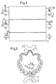
- Fig. 1 shows schematically a calender 1 with two end rolls 2, 3, which are designed as deflection rollers and three center rollers 4-6, which together form one Form the roll stack.
- the roll stack has a roll plane 7, in which the axes of all rollers 2 - 6 lie when the rollers 2 - 6 are arranged exactly one above the other are.
- this roller plane 7 lies for the
- press direction i.e. the direction in which the reels 2-6 pressed against each other.
- rollers 2 - 6 form during operation of the calender in known manner nips 10-13, through which one to be treated Material web is guided. All nips are here formed as so-called soft nips because they are from a hard and limited by a soft roller.
- Vibration transducers 20, 21, 22 (Fig. 2) arranged which vibrates the center rollers Determine 4 - 6.
- the vibration sensors 20 - 22 are preferably on the bearing 23, more precisely on the bearing housing 24 arranged.
- the vibration sensors determine this 20 vibrations in the vertical direction, the vibration sensor 21 vibrations perpendicular to Roller plane, i.e. the plane through the central axes of the (non-offset) rollers 2 - 6, and the vibration sensor 22 vibrations in the axial direction.
- the vibration sensors 20 - 22 in the Can basically determine any direction of vibration, as long as the directions are orthogonal to each other.
- the vibration sensors 20-22 are connected to one Regulator 25, which in turn is based on an adjustment drive 26 acts.
- the controller 25 also has a frequency analysis device 27 on that with a not shown Comparator and a threshold element coupled could be.
- the frequency analysis device 27 determined from the vibrations by the vibration sensors 20 - 22 are recorded, the amplitude Percentage of a frequency (or a narrow frequency range) can be assigned.
- the adjustment drive 26 in Operation set to cross the appropriate roller To adjust the press direction. This is schematic in Fig. 1 shown for the middle roller 5. It but it is obvious that basically all rollers 2 - 6 can be adjusted.
- the original barring pattern is one wavelength U / n, where U is the circumference of the roller 5, then has the new barring pattern may be a wavelength of U / (n ⁇ 1). Until such a new barring pattern but so far that it bothers some that passes Time.
- the aim here is a phase shift by the controller 25, which is closer to ⁇ / 2.
- the danger, connected with a phase shift of ⁇ / 2 is that after the initial pattern is canceled a new pattern is created by the Regulation counteracted.
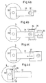
- Fig. 4 now shows different ways to To cause roll misalignment. The explanation is given in all cases using the example of the center roller 5, which in one Bearing housing 30 is mounted, which is on the front End of a lever 31 is located.
- the lever is 31st stored with a bearing point 32 in an eccentric sleeve 33. If the eccentric bushing 33 is rotated, then the position of the roller 5 changes in horizontal Direction.
- the lever 31 stored in a sliding block 34 which is in a housing 35 by a linear drive 36, which is only schematic is shown, can be moved in the housing 35.
- the linear drive can be used, for example, as a threaded spindle will be realized. Also with a threaded spindle relatively precise adjustment movements are possible.
- the lever is 31 adjustable in length, which is indicated by a double arrow 37 is shown.
- the lever 31 can for example have a telescopic or a prismatic guide.
- the drive of the two movable against each other Parts of the lever can also be threaded (not shown).
- a schematically represented Tilt drive 40 is provided around the bearing housing 30 compared to the lever 31 by a defined amount to tip.
Landscapes
- Paper (AREA)
- Casting Or Compression Moulding Of Plastics Or The Like (AREA)
Applications Claiming Priority (2)
| Application Number | Priority Date | Filing Date | Title |
|---|---|---|---|
| DE10133888 | 2001-07-12 | ||
| DE10133888A DE10133888C1 (de) | 2001-07-12 | 2001-07-12 | Verfahren zum Betreiben eines Kalanders und Kalander |
Publications (2)
| Publication Number | Publication Date |
|---|---|
| EP1275774A1 true EP1275774A1 (fr) | 2003-01-15 |
| EP1275774B1 EP1275774B1 (fr) | 2007-01-03 |
Family
ID=7691527
Family Applications (1)
| Application Number | Title | Priority Date | Filing Date |
|---|---|---|---|
| EP02014376A Expired - Lifetime EP1275774B1 (fr) | 2001-07-12 | 2002-06-28 | Procédé pour le fonctionnement d'une calandre et calandre |
Country Status (4)
| Country | Link |
|---|---|
| US (1) | US6857356B2 (fr) |
| EP (1) | EP1275774B1 (fr) |
| CA (1) | CA2393248C (fr) |
| DE (2) | DE10133888C1 (fr) |
Families Citing this family (9)
| Publication number | Priority date | Publication date | Assignee | Title |
|---|---|---|---|---|
| FI20030377A0 (fi) * | 2003-03-13 | 2003-03-13 | Metso Paper Inc | Menetelmä kalanteroinnissa ja kalanteri |
| DE10343980B4 (de) * | 2003-09-19 | 2005-08-18 | Eduard Küsters Maschinenfabrik GmbH & Co. KG | Kalander |
| FI115984B (fi) * | 2003-11-27 | 2005-08-31 | Metso Paper Inc | Menetelmä ja järjestely värähtelyn estämiseksi moninippikalanterissa tai -kalanteriryhmässä |
| FI117301B (fi) * | 2005-02-11 | 2006-08-31 | Metso Paper Inc | Rainankäsittelykoneen telan laakerointi ja menetelmä telavärähtelyn vaimentamiseksi |
| FI118812B (fi) | 2006-02-01 | 2008-03-31 | Metso Paper Inc | Menetelmä kalanterin välitelan värähtelyn ominaistaajuuden hallitsemiseksi ja värähtelyn vaimennin |
| FI119851B (fi) | 2007-09-28 | 2009-04-15 | Metso Paper Inc | Menetelmä kuiturainakoneen jaksollisen värähtelyn vaimentamiseksi |
| FI119335B (fi) | 2007-09-28 | 2008-10-15 | Metso Paper Inc | Monitelakalanteri |
| JP5123654B2 (ja) * | 2007-12-11 | 2013-01-23 | 住友化学株式会社 | 押出樹脂板の製造方法 |
| DE102010002703A1 (de) * | 2010-03-09 | 2011-09-15 | Metso Paper, Inc. | Anordnung und Verfahren zur Regelung einer Kraft in einem Spalt zwischen zwei Walzen |
Citations (5)
| Publication number | Priority date | Publication date | Assignee | Title |
|---|---|---|---|---|
| US3044392A (en) * | 1959-07-10 | 1962-07-17 | Kimberly Clark Co | Papermaking machine |
| WO1999025921A1 (fr) * | 1997-11-17 | 1999-05-27 | Valmet Corporation | Procede de detection d'impuretes et/ou d'endommagement d'une face passant a travers une ligne de contact ou des lignes de contact dans une calandre pour papier |
| US5961899A (en) * | 1997-07-15 | 1999-10-05 | Lord Corporation | Vibration control apparatus and method for calender rolls and the like |
| EP0949378A1 (fr) * | 1998-04-06 | 1999-10-13 | Voith Sulzer Papiertechnik Patent GmbH | Machine à rouleaux et son procédé de fonctionnement |
| EP1127977A2 (fr) * | 2000-02-25 | 2001-08-29 | Voith Paper Patent GmbH | Procédé de fonctionnement d' un rouleau de calandre et un rouleau de calandre |
Family Cites Families (8)
| Publication number | Priority date | Publication date | Assignee | Title |
|---|---|---|---|---|
| NL299751A (fr) * | 1962-10-26 | |||
| FI64902C (fi) * | 1976-03-30 | 1984-02-10 | Wiik & Hoeglund | Foerfarande foer kompensering av valsboejningen i en kalander |
| US4348952A (en) * | 1981-01-19 | 1982-09-14 | Usm Corporation | Cross axis mechanism |
| US4516491A (en) * | 1983-09-30 | 1985-05-14 | Usm Corporation | Roll cross-axis mechanism |
| GB2161105B (en) * | 1984-07-04 | 1988-06-15 | Fred Whitehead | Calendar or roll assembly |
| DE4314653C2 (de) * | 1993-05-04 | 1997-01-30 | Troester Maschf Paul | Mehrzweckkalander |
| DE19601293C2 (de) | 1996-01-16 | 1999-09-16 | Voith Sulzer Finishing Gmbh | Verfahren und Vorrichtung zum Behandeln einer Materialbahn |
| DE19832067B4 (de) * | 1998-07-16 | 2005-04-21 | Voith Paper Patent Gmbh | Kalander für Bahnen aus Papier oder ähnlichem Material |
-
2001
- 2001-07-12 DE DE10133888A patent/DE10133888C1/de not_active Expired - Fee Related
-
2002
- 2002-06-28 DE DE50209131T patent/DE50209131D1/de not_active Expired - Lifetime
- 2002-06-28 EP EP02014376A patent/EP1275774B1/fr not_active Expired - Lifetime
- 2002-07-11 CA CA002393248A patent/CA2393248C/fr not_active Expired - Fee Related
- 2002-07-11 US US10/192,499 patent/US6857356B2/en not_active Expired - Fee Related
Patent Citations (5)
| Publication number | Priority date | Publication date | Assignee | Title |
|---|---|---|---|---|
| US3044392A (en) * | 1959-07-10 | 1962-07-17 | Kimberly Clark Co | Papermaking machine |
| US5961899A (en) * | 1997-07-15 | 1999-10-05 | Lord Corporation | Vibration control apparatus and method for calender rolls and the like |
| WO1999025921A1 (fr) * | 1997-11-17 | 1999-05-27 | Valmet Corporation | Procede de detection d'impuretes et/ou d'endommagement d'une face passant a travers une ligne de contact ou des lignes de contact dans une calandre pour papier |
| EP0949378A1 (fr) * | 1998-04-06 | 1999-10-13 | Voith Sulzer Papiertechnik Patent GmbH | Machine à rouleaux et son procédé de fonctionnement |
| EP1127977A2 (fr) * | 2000-02-25 | 2001-08-29 | Voith Paper Patent GmbH | Procédé de fonctionnement d' un rouleau de calandre et un rouleau de calandre |
Non-Patent Citations (2)
| Title |
|---|
| M. HERMANSKI: "Barringbildung am Glättkalander einer Papiermaschine", DAS PAPIER, no. 9, 1995, pages 581 - 590, XP001118222 * |
| Y.N. CHEN ET.AL.: "Calender barring on paper machines-practical conclusions and recommendations", TAPPI JOURNAL, vol. 58, no. 8, 1975, pages 147 - 151, XP002216957 * |
Also Published As
| Publication number | Publication date |
|---|---|
| US6857356B2 (en) | 2005-02-22 |
| DE10133888C1 (de) | 2002-11-28 |
| CA2393248C (fr) | 2007-12-18 |
| DE50209131D1 (de) | 2007-02-15 |
| US20030024415A1 (en) | 2003-02-06 |
| CA2393248A1 (fr) | 2003-01-12 |
| EP1275774B1 (fr) | 2007-01-03 |
Similar Documents
| Publication | Publication Date | Title |
|---|---|---|
| EP0854233B1 (fr) | Procédé et appareil pour l'amortissement des vibrations de rouleaux en contact et en rotation | |
| DE10248519B4 (de) | Mittelwalze eines Kalanders und Kalander | |
| WO2003064763A1 (fr) | Procede et dispositif pour reduire des vibrations sur des composants en rotation | |
| EP0949378B1 (fr) | Machine à rouleaux et son procédé de fonctionnement | |
| DE10133888C1 (de) | Verfahren zum Betreiben eines Kalanders und Kalander | |
| DE3815445C2 (fr) | ||
| DE10133891C1 (de) | Kalander und Verfahren zum Anordnen von Walzen in einem Walzenstapel eines Kalanders | |
| EP1275777B1 (fr) | Procédé pour le fonctionnement d'une calandre | |
| DE102008002454B4 (de) | Papiermaschinenwalze und Schwingungstilger | |
| DE102008000267A1 (de) | Verfahren zur Entwässerung und Entwässerungsvorrichtung | |
| EP1275775B1 (fr) | Procédé pour le fonctionnement d'une calandre | |
| AT506025B1 (de) | Verfahren und vorrichtung zur dämpfung von walzenschwingungen | |
| DE19907079A1 (de) | Verfahren und Vorrichtung zum Vermeiden von Kontaktschwingungen rotierender Walzen in einer Maschine zur Herstellung oder/und Behandlung einer Materialbahn | |
| EP1333123B1 (fr) | Procédé et dispositif d'amortissement actif dans un dispositif de traitement d'une bande en mouvement continu | |
| EP1790600A2 (fr) | Enrouleuse | |
| DE29624490U1 (de) | Vorrichtung zur Dämpfung von Kontaktschwingungen rotierender Walzen | |
| EP1225274B1 (fr) | Procédé pour le traitement d' une bande de matière et calandre | |
| DE112006000227T5 (de) | Lagerbaugruppe für eine Walze in einer Bahnbehandlungsmaschine, und Verfahren zur Dämpfung von Walzenschwingungen | |
| DE112004000421T5 (de) | Kalander und Kalandrierungsverfahren | |
| EP2128337B1 (fr) | Procédé de fonctionnement d'une calandre et calandre | |
| DE102008041905A1 (de) | Pressenvorrichtung | |
| DE19907078A1 (de) | Verfahren und Vorrichtung zum Vermeiden von Kontaktschwingungen rotierender Walzen in einer Maschine zur Herstellung einer Materialbahn, insbesondere aus Papier oder Karton | |
| WO2022253562A1 (fr) | Dispositifs de traitement par ultrasons dotés d'un élément de support | |
| DE102007047904A1 (de) | Walzenanordnung einer Faserstoffbahn-Behandlungsmaschine | |
| WO2004001124A1 (fr) | Dispositif pour modifier et/ou controler un profil de pression |
Legal Events
| Date | Code | Title | Description |
|---|---|---|---|
| PUAI | Public reference made under article 153(3) epc to a published international application that has entered the european phase |
Free format text: ORIGINAL CODE: 0009012 |
|
| AK | Designated contracting states |
Kind code of ref document: A1 Designated state(s): AT BE CH CY DE DK ES FI FR GB GR IE IT LI LU MC NL PT SE TR |
|
| AX | Request for extension of the european patent |
Free format text: AL;LT;LV;MK;RO;SI |
|
| 17P | Request for examination filed |
Effective date: 20021122 |
|
| AKX | Designation fees paid |
Designated state(s): DE FI SE |
|
| GRAP | Despatch of communication of intention to grant a patent |
Free format text: ORIGINAL CODE: EPIDOSNIGR1 |
|
| RAP1 | Party data changed (applicant data changed or rights of an application transferred) |
Owner name: VOITH PATENT GMBH |
|
| GRAS | Grant fee paid |
Free format text: ORIGINAL CODE: EPIDOSNIGR3 |
|
| GRAA | (expected) grant |
Free format text: ORIGINAL CODE: 0009210 |
|
| AK | Designated contracting states |
Kind code of ref document: B1 Designated state(s): DE FI SE |
|
| REF | Corresponds to: |
Ref document number: 50209131 Country of ref document: DE Date of ref document: 20070215 Kind code of ref document: P |
|
| REG | Reference to a national code |
Ref country code: SE Ref legal event code: TRGR |
|
| PLBE | No opposition filed within time limit |
Free format text: ORIGINAL CODE: 0009261 |
|
| STAA | Information on the status of an ep patent application or granted ep patent |
Free format text: STATUS: NO OPPOSITION FILED WITHIN TIME LIMIT |
|
| 26N | No opposition filed |
Effective date: 20071005 |
|
| PGFP | Annual fee paid to national office [announced via postgrant information from national office to epo] |
Ref country code: SE Payment date: 20120621 Year of fee payment: 11 |
|
| PGFP | Annual fee paid to national office [announced via postgrant information from national office to epo] |
Ref country code: DE Payment date: 20130620 Year of fee payment: 12 |
|
| PGFP | Annual fee paid to national office [announced via postgrant information from national office to epo] |
Ref country code: FI Payment date: 20130613 Year of fee payment: 12 |
|
| PG25 | Lapsed in a contracting state [announced via postgrant information from national office to epo] |
Ref country code: SE Free format text: LAPSE BECAUSE OF NON-PAYMENT OF DUE FEES Effective date: 20130629 |
|
| REG | Reference to a national code |
Ref country code: SE Ref legal event code: EUG |
|
| REG | Reference to a national code |
Ref country code: DE Ref legal event code: R119 Ref document number: 50209131 Country of ref document: DE |
|
| PG25 | Lapsed in a contracting state [announced via postgrant information from national office to epo] |
Ref country code: FI Free format text: LAPSE BECAUSE OF NON-PAYMENT OF DUE FEES Effective date: 20140628 |
|
| REG | Reference to a national code |
Ref country code: DE Ref legal event code: R119 Ref document number: 50209131 Country of ref document: DE Effective date: 20150101 |
|
| PG25 | Lapsed in a contracting state [announced via postgrant information from national office to epo] |
Ref country code: DE Free format text: LAPSE BECAUSE OF NON-PAYMENT OF DUE FEES Effective date: 20150101 |