EP1275527A2 - Laufflächenprofil für einen Fahrzeugreifen, Stift als Vorrichtung zur Herstellung eines solchen Laufflächenprofils und Vulkanisationsform mit einem solchen Stift - Google Patents
Laufflächenprofil für einen Fahrzeugreifen, Stift als Vorrichtung zur Herstellung eines solchen Laufflächenprofils und Vulkanisationsform mit einem solchen Stift Download PDFInfo
- Publication number
- EP1275527A2 EP1275527A2 EP02013037A EP02013037A EP1275527A2 EP 1275527 A2 EP1275527 A2 EP 1275527A2 EP 02013037 A EP02013037 A EP 02013037A EP 02013037 A EP02013037 A EP 02013037A EP 1275527 A2 EP1275527 A2 EP 1275527A2
- Authority
- EP
- European Patent Office
- Prior art keywords
- pin
- tread
- channels
- bolt
- cup
- Prior art date
- Legal status (The legal status is an assumption and is not a legal conclusion. Google has not performed a legal analysis and makes no representation as to the accuracy of the status listed.)
- Granted
Links
Images


Classifications
-
- B—PERFORMING OPERATIONS; TRANSPORTING
- B60—VEHICLES IN GENERAL
- B60C—VEHICLE TYRES; TYRE INFLATION; TYRE CHANGING; CONNECTING VALVES TO INFLATABLE ELASTIC BODIES IN GENERAL; DEVICES OR ARRANGEMENTS RELATED TO TYRES
- B60C11/00—Tyre tread bands; Tread patterns; Anti-skid inserts
- B60C11/03—Tread patterns
- B60C11/04—Tread patterns in which the raised area of the pattern consists only of continuous circumferential ribs, e.g. zig-zag
-
- B—PERFORMING OPERATIONS; TRANSPORTING
- B29—WORKING OF PLASTICS; WORKING OF SUBSTANCES IN A PLASTIC STATE IN GENERAL
- B29D—PRODUCING PARTICULAR ARTICLES FROM PLASTICS OR FROM SUBSTANCES IN A PLASTIC STATE
- B29D30/00—Producing pneumatic or solid tyres or parts thereof
- B29D30/06—Pneumatic tyres or parts thereof (e.g. produced by casting, moulding, compression moulding, injection moulding, centrifugal casting)
- B29D30/0601—Vulcanising tyres; Vulcanising presses for tyres
- B29D30/0606—Vulcanising moulds not integral with vulcanising presses
-
- B—PERFORMING OPERATIONS; TRANSPORTING
- B60—VEHICLES IN GENERAL
- B60C—VEHICLE TYRES; TYRE INFLATION; TYRE CHANGING; CONNECTING VALVES TO INFLATABLE ELASTIC BODIES IN GENERAL; DEVICES OR ARRANGEMENTS RELATED TO TYRES
- B60C11/00—Tyre tread bands; Tread patterns; Anti-skid inserts
- B60C11/01—Shape of the shoulders between tread and sidewall, e.g. rounded, stepped or cantilevered
-
- B—PERFORMING OPERATIONS; TRANSPORTING
- B60—VEHICLES IN GENERAL
- B60C—VEHICLE TYRES; TYRE INFLATION; TYRE CHANGING; CONNECTING VALVES TO INFLATABLE ELASTIC BODIES IN GENERAL; DEVICES OR ARRANGEMENTS RELATED TO TYRES
- B60C11/00—Tyre tread bands; Tread patterns; Anti-skid inserts
- B60C11/03—Tread patterns
- B60C11/0306—Patterns comprising block rows or discontinuous ribs
-
- B—PERFORMING OPERATIONS; TRANSPORTING
- B60—VEHICLES IN GENERAL
- B60C—VEHICLE TYRES; TYRE INFLATION; TYRE CHANGING; CONNECTING VALVES TO INFLATABLE ELASTIC BODIES IN GENERAL; DEVICES OR ARRANGEMENTS RELATED TO TYRES
- B60C11/00—Tyre tread bands; Tread patterns; Anti-skid inserts
- B60C11/03—Tread patterns
- B60C11/032—Patterns comprising isolated recesses
- B60C11/0323—Patterns comprising isolated recesses tread comprising channels under the tread surface, e.g. for draining water
-
- B—PERFORMING OPERATIONS; TRANSPORTING
- B60—VEHICLES IN GENERAL
- B60C—VEHICLE TYRES; TYRE INFLATION; TYRE CHANGING; CONNECTING VALVES TO INFLATABLE ELASTIC BODIES IN GENERAL; DEVICES OR ARRANGEMENTS RELATED TO TYRES
- B60C11/00—Tyre tread bands; Tread patterns; Anti-skid inserts
- B60C11/03—Tread patterns
- B60C11/11—Tread patterns in which the raised area of the pattern consists only of isolated elements, e.g. blocks
-
- B—PERFORMING OPERATIONS; TRANSPORTING
- B60—VEHICLES IN GENERAL
- B60C—VEHICLE TYRES; TYRE INFLATION; TYRE CHANGING; CONNECTING VALVES TO INFLATABLE ELASTIC BODIES IN GENERAL; DEVICES OR ARRANGEMENTS RELATED TO TYRES
- B60C11/00—Tyre tread bands; Tread patterns; Anti-skid inserts
- B60C11/03—Tread patterns
- B60C11/13—Tread patterns characterised by the groove cross-section, e.g. for buttressing or preventing stone-trapping
-
- B—PERFORMING OPERATIONS; TRANSPORTING
- B29—WORKING OF PLASTICS; WORKING OF SUBSTANCES IN A PLASTIC STATE IN GENERAL
- B29D—PRODUCING PARTICULAR ARTICLES FROM PLASTICS OR FROM SUBSTANCES IN A PLASTIC STATE
- B29D30/00—Producing pneumatic or solid tyres or parts thereof
- B29D30/06—Pneumatic tyres or parts thereof (e.g. produced by casting, moulding, compression moulding, injection moulding, centrifugal casting)
- B29D30/0601—Vulcanising tyres; Vulcanising presses for tyres
- B29D30/0606—Vulcanising moulds not integral with vulcanising presses
- B29D2030/0607—Constructional features of the moulds
- B29D2030/0612—Means for forming recesses or protrusions in the tyres, e.g. grooves or ribs, to create the tread or sidewalls patterns
Definitions
- EP-PA 0 342 908 A2 teaches to bridge a transverse groove outlet on the vehicle outer shoulder with a rubber track.
- EP-PA 0 540 340 A2 discloses cuts in tire treads which are thicker in their nature than at the tire periphery.
- Tread profile specify that on the one hand excellent Grip on wet roads and a very high speed limit for aquaplaning, on the other hand also an optimal grip on dry road at only low abrasion provides.
- the inventors have recognized that the initially so willing Cup the intake of more water into one Time points largely deny, where they only about one Third are filled with water. The inventors have further recognized that this is the increasing pressure of the wells remaining air is responsible.
- the core idea of Invention is thus to offer the air channels to escape so that the bowls can be completely filled with water.
- the venting channel between two wells one have smaller cross-sectional area than the bowls themselves to have. And this channel also needs a much smaller one Have cross-sectional area to the tread pattern one To be able to obtain the largest possible positive surface area, the the grip on dry roads increases and the Tread depth loss above mileage lowers. That's why the cross-sectional area of the channels in the invention Tread profile highest 50% of the cup cross-sectional area, most preferably about 25%. The lower limit is 10% established.
- the channels serve their purpose especially Perfectly meet when in a compression-free End room.
- the channels should either be up to one Reach the tire shoulder, or in a circumferential groove or itself cover the entire tire circumference. It seems the last solution at least for cups in the tread center area to be the cheapest.
- the basic idea further to create a low-resistance air removal from wells with the lowest possible positive surface loss the inventors have come to a further improvement in that the channel of the cups a Napkehe together, below, ie in the vicinity of the full tread depth, a Has greater width than above, ie near the periphery of the profiled tread.
- the cross-sectional area of such Napfentlcommunungskanales may particularly preferably be a trapezoid, with the smaller of the two parallel sides of the trapezoid should form the tread periphery.
- a tire profile produced with superficially isolated Negatives leave the remaining, coherent positive the maximum possible stiffness, which is a particularly soft and sticky rubber compound without handling disadvantages allowed.
- a profile shape also allows the Use relatively hysteresereicher and thus in the wet grip especially favorable mixtures, because the bowls venting channels also have a considerable cooling effect reach the air flowing through. In addition, this is Cooling effect at the most critical point, namely the Center of the positive root at the base, concentrated.
- a vulcanization mold according to claim 14 , the novelty of which is that it contains a pin (30) according to claim 6 .
- a pin (30) is characterized in that it has at least in the area which is to form a cup of a tread profile in the vicinity of the full tread depth, at least one bolt (31) which is displaceable transversely to the longitudinal extent of the pin (30) ,
- a vulcanization mold with such pins should be operated so that the sliding pins are still within the respective pin during the closing of the vulcanization mold and the Resterarias of the green tire, which leads in a conventional manner for impressing the tread profile. So far, therefore, the generated profile of the tread still no channels according to claim 6. Only after completion of the recovery - and as directly as possible thereafter, so that the polymer viscosity has barely risen by cross-linking - should the bolts from the pins transversely (ie in the tire circumferential direction or in the axial direction of the tire or in directions consisting of both aforementioned components are composed) and preferably - according to claim 13 - hydraulically.
- the extendible length of a one-piece sliding Bolzens must of course be smaller than the length of the cup, in which the bolt is retractable. A certain overlap must be between the bolt and the cross hole in the cup in which the Bolt is guided, remain to tilt the bolt to exclude and to a sufficient tightness against Outlet of serving as hydraulic fluid to the oil To achieve displacement of the bolt.
- each sliding bolt should at least after installation of the pin containing this pin be limited in some way to a vulcanization mold, to prevent the bolt from falling out of the pin and Large quantities of oil into the cavern of the vulcanization mold penetrates. This is possible, for example, by the fact that the Bolt of a pin in its ejected state strikes against the "back wall” of the next pin. It is meant with “back wall” the wall of a pen, which the Outlet opening of its sliding bolt opposite lies.
- the pins are particularly light producible, but somewhat difficult to act and in the Vulcanization mold to assemble, as long as the sliding Bolts are not arranged captive in the pin.
- the captivity is achieved when the the Ausschiebeweg a bolt of a pin limiting Stop function not or at least not only by Resort to the adjacent in the Aus fürungichtung pin but within the same pen.
- the inventive expulsion of a bolt in one of the Level of the belt layers of the tire parallel plane has several Side effects: On the one hand, one of the ejection orientation is created at the pen opposite reaction force to the pin stressed on shear and bending and on the other arises on the green tire a tendency in the Orientation of the pin extension to twist.
- the invention appears particularly easy to enforce, if the aforementioned side effects are completely compensated for the smallest possible area units.
- a refinement of the invention is recommended according to claim 8 , according to which the pin (30) in the region which is to form the cup in the vicinity of the full tread depth, at least two bolts (31, 35) which transversely to the Longitudinal extension of the pin (30) are displaceable, one in the one orientation and the other along the same straight line, but in the opposite orientation.
- such a pin with two opposing, sliding bolt is even particularly easy to produce, and especially in such an embodiment, which is hereinafter referred to as a "tandem pin".
- a return spring - continue preferably used as a tension spring wire helix spring, in Machinist jargon also known as worm feather - for the Push back the bolt just before opening the Vulcanization mold succeeds more easily with a pin design as a tandem stick, because at least the significant drag is so no longer by a difficult to produce and mount Anchoring on the back of the housing as in a singular Pen needs to be generated, but simply by Attachment to the inversely displaceable second piston.
- An essential element of the invention is that the channels between the wells are continuous.
- the problem is feared that then inevitably even a very short period of time to extend the Bolt of the rubber mixture could not leave enough time to completely avoid the hurrying end side or the mutually abrupt end faces of the bolt (s); So it is feared that in the middle of the channel could remain a thin Gumminosutchen.
- the claim 10 teaches for a tandem pin, that the no sharp edged edge (32) having bolts (35) of the two oppositely transversely from the pin (30) out sliding bolt (31, 35) on its leading during ejection End face has a diameter (D S ) which is just as large or slightly smaller, as or as the inner diameter (d S ) of the raised, sharp-edged edge (32) of the other, a raised sharp-edged edge having bolt (31).
- claim 12 teaches for a single pin (30) that it has a diameter (D S ) on the wall face opposite the bolt outlet opening or on the leading end face of the pin (30) which can be pushed out of the pin (30) , which is just as large or slightly smaller, as or as the inner diameter (d S ) of the raised, sharp-edged edge (32) on the leading end face of the bolt (31) or on the wall surface opposite the bolt outlet opening.
- D S diameter
- both have surfaces meeting each other a raised, sharp edge and enclosed in it one sink each; both together then act like Scissor blades.
- the drive works for both displacement orientations by means of a hydraulic drive. This is the most space-saving way to realize that not only an oil pressure line in front of the piston of Freedomebenden Bolzens opens, but also another oil pressure line behind the same piston opens. This latter oil pressure line The oil supply serves to push back the piston.
- a pneumatic drive instead of the previously explained Although hydraulic drive could also high forces Redirect in a confined space, but would firstly have the disadvantage that due to the compressibility of gases high energies in the volumes between pump and slidable bolt stored in the event of a Zulungsungsplatzers People and machines would endanger, secondly the Disadvantage that - again because of the compressibility - would result in significant temperature variations on the bolt, the reproducibility of the vulcanization conditions thirdly and the disadvantage that eventually occurring small leakage currents at the sliding seals as here between pin housing and sliding bolt never are completely ruled out, to a bubble in the Vulcanizate would lead and thus the manufacturing quality would affect.
- Hydraulic fluid should reach a temperature of 30 ° C above the Vulkanisationspressentemperatur, so about to 190 ° C, in the air can not ignite spontaneously to ensure a high work safety.
- the oil should be used with those for tire treads commonly used rubber compounds, in particular on NBR, SBR, Soot and silica constituent mixtures, given the not be completely suppressed to be suppressed leakage currents.
- the depth of the wells produced according to the invention should be of the same order of magnitude, as has been the greatest depth of tread profiling so far. In this way, no changes in the semifinished product manufacturing and delivery are required when converted in a tire production line from a conventional grooved tread profiling to an inventive. Accordingly, according to claim 2, the depth (t) of the cups (10a, 10b, ... 13d, 13e) when used on tires should for light motorcycles up to approx. 125 ccm approx. 4 mm, for medium motorcycles up to approx. 350 ccm approx. 5.5 mm, for heavy motorcycles approx. 7 mm, for car and transporter tires approx. 8mm, for light truck tires approx.
- the near-bottom channels preferably have a height, that is an extension in the radial Direction of the tire, from 15% to 35% of the well depth and a width of 20% to 80% of the well depth. More preferably, they have a height of 25% and a width of 60% of the well depth.
- the main claim of this patent application is therefore not on a vehicle tire with profiled tread but directed to a tread pattern because of it - in particular for the purpose of tire retreading and Refinement - it is conceivable that a manufacturer A only the Tread finished profiled and at least partially Vulkaninstrument manufactures and sells to manufacturer B, the first making a tire out of it; the claims are directed against both manufacturers. Also for the production of such separate tread invention becomes a Vulcanization mold according to claim 14 with pins according to one of claims 6 to 13 required.
- FIG. 1 shows, to scale, a first vehicle tire 1, namely a solid tire, which can be used not only on industrial trucks but also on vehicles for seaports, inland ports, airports and railway stations, in particular forklifts or trailers. Such vehicles also drive or even predominantly on uncontrolled surfaces.
- a first vehicle tire 1 namely a solid tire
- Such vehicles also drive or even predominantly on uncontrolled surfaces.
- For maneuverability and compactness, very high load-bearing capacities per installation space, good grip for climbing wet ramps and a long service life are expected to limit the maintenance effort and downtimes. To meet the grip requirements, it is common to profile the tread. However, the positive loss that can be assumed reduces the carrying capacity and the service life.
- FIG. 1 A vulcanization mold for producing a tire 1 according to Incidentally, FIG. 1 is shown in longitudinal section in FIG.
- this tread pattern has a left of the Nap réelle X arranged circumferential groove 5 and a right of the Napfreihe X arranged circumferential groove 6.
- this conventional circumferential grooves 5, 6 by per se known Cross grooves are replaced or - even better - by more Napkahen.
- a very extreme traction grip can be reach, if in the shoulders substantially axially extending Napkahen are arranged; this consideration leads to an embodiment according to the next figure:
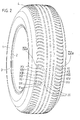
- Figure 2 shows to scale a pneumatic vehicle tire 1 for cars with beads 2, side walls 3 and a tread 4. On the latter is an inventive tread profile, which includes only Napherhen.
- this tread 4 also has a variety of substantially axially extending another well XI, XII, XIII, XIV and XV. These in the circumferential direction successive Napierhen XI, XII, XIII, XIV and XV should show the variety of possible embodiments.
- the Nap #2 XII differs from the Nap #2 XI in that they instead of cups with rectangular Top view has such with circular top view. Yet more important is that here also the bowls with each other connecting channels not completely submerged, but to Laufzanperipherie are open like a slit. This facilitates the mold making, but also worsens clearly the positive stiffness compared to an execution XI. After all, however, remains opposite to an execution of a Nap réelle according to XV a higher positive. A cut through Such a channel 22 transverse to the main line 12, as shown in FIG 4a in the second row of cells XII from the right shows is from keyhole-like shape.
- the Nap nurse XIII shows again like the Nap réelle XI rectangular bowls.
- the channels connecting the cups with each other 23 (see 4a) not completely submerged, but for Laufzanperipherie slit open.
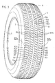
- FIG. 3 shows, to scale, another pneumatic vehicle tire 1 for cars with a tread pattern according to the invention. In the shoulders, this profile is largely identical to that of FIG. 2, and therefore shows essentially axially extending row rows XI, XII, XIII, XIV and XV there.
- the middle region of the tread 4 of the tire 1 according to FIG. 3 is to the shoulders through each a circumferential groove 7, 8 limited. In the middle, it has a further circumferential groove 9 on. Both between the circumferential grooves 7 and 9 as well between the circumferential grooves 9 and 8 are each a crowd in Circumferential direction successive, essentially transversely extending Nap #2n XVI on. Their bowls are of a circular nature Top view. Between these wells are channels 26 arranged, which have a trapezoidal cross-section and are narrower in the periphery than at the bottom of the profile.
- the exceptionally small Quernegativanteil lowers the running noise in conjunction with the sound-absorbing acting Napkehen XVI. Furthermore, it shows an excellent self-sharpening edge grip, which makes the winter suitability this profile increases. Because the circumferential grooves 7 to 9 the Obtain water and air removal in the circumferential direction and in Remain essentially free of compression even on wet roads, Here, all Napeghen can be aligned substantially axially be and still stand with the compression-free space outside the tire gossip in a conductive connection.
- FIG. 4a shows on an enlarged scale a part of an outer positive strip of the tire according to FIG. 2
- FIG. 4b shows on an enlarged scale a part of an outer positive strip of the tire according to FIG. 3. Its content is already in connection with FIGS. 2 and 3, respectively explained.
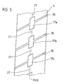
- Figure 5 shows a detail of a development of another profile according to the invention a tread 4, in which a family of known transverse grooves 30 of a circumferentially extending, continuous strand of adjoining channels 27 are crossed and at each intersection of a respective cup XVII is arranged.
- These cups XVII increase the water absorption capacity in the tread center area, from which water is the most difficult to dissipate, because from here the discharge paths are the longest.
- the generously sized cups allow - as in the related embodiment of Figure 1 - the intermediate storage of considerable amounts of water until the time when the cup in question exceeds the trailing limit of the laces, so again lifts off the street, the cup thus emptied.
- the circumferentially extending, recessed channels 27, the form a strand of channels, serve to make without further Enlargement of these cups XVII their water absorption capacity to further increase and reduce the noise emission Air column displacement from the crossing transverse grooves 30 low to keep; the channels 27 vent the vials XVII.
- the for Napferschiung to be provided in the vulcanization mold Pins also provide the space to make it - at the beginning of the Profile embossing - or darein - at the end of vulcanization - Push bolts that produce the channels 27.
- Figure 6 shows a detail of a development of another tread strip according to the invention, in which two known longitudinal grooves 5, 6 crossed by a crowd in the diagonal direction, continuous strands of adjoining channels and at each intersection each a cup is arranged,
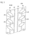
- Figure 7 shows a detail of a settlement of another tread pattern according to the invention with four known longitudinal grooves 40, 41, 42 and 43rd
- the two left longitudinal grooves 40 and 41 by a left bank of diagonal, continuous strands adjacent channels 28 with the left edge of the Tread connected. Only at the intersection of this Channel strands with the leftmost circumferential groove 40 is one each Cup of Nap réelle XVIII arranged.
- the two right longitudinal grooves 42 and 43 are through a right bank of diagonal, continuous strands adjacent channels 29 with the right edge of the Tread connected and only at the intersection of this Channel strands with the rightmost circumferential groove 43 is ever one Cup of Nap #2 XIX arranged.
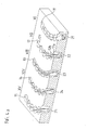
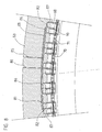
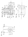
- FIG. 8 shows a longitudinal section through a segment 50 of a radially divided vulcanization mold according to the invention for the production of tires according to the invention; the shape is shown empty, without tires inside.
- the cutting plane extends centrally through the segment 50 in the circumferential direction and thus through the center of the pins 60 and their outwardly and retractable bolts 70 and 71.
- the pins 60 and the sliding pins 70 and 71 are not hatched, because this would have produced such a high degree of blackening on the paper that clarity and duplication would have suffered.
- the bolts 70 and 71 are in their pushed out position displayed. This state they have achieved by that previously by means of a - commercially available and therefore here not shown - heat-resistant high-pressure hose oil was pumped into the oil pressure passage 80.
- Distribution line 81 and the pin supply lines 82 passes the oil then to the interior of the pen facing piston surfaces and pushes them outward against the flow resistance of the Rubber of the tread of not shown here Tire and the contrast, very low resistance of the Tension spring 90. Meanwhile, the other oil pressure passage 85 kept pressure-free.
- the bolts 70 and 71 could be their pushed in position achieve that the oil pressure passage 80 pressure-free is switched and now by means of another - commercially available and therefore not shown here - heat resistant high pressure hose oil in the oil pressure channel 85 is pumped.
- the distribution line 86 and the Pin supply lines 87 then passes the oil to the outside of the pin turned piston surfaces and pushes them inwards against the elastic resistance of the easily adherent Rubbers of the tread of the tire. This movement will slightly supported by the tension spring 90th
- the pins 60 in this device embodiment according to FIG. 8 are different from another, explained later Design also known as "tandem pens”.
- Figures 9 show such a tandem pin 60 in an enlarged scale, which now also allows the hatching of all cut surfaces and the specification of further details. What is essential is that it has both a bolt 71, which can be moved in and out to the left (70) and an opponent thereto.
- FIG. 9a shows a longitudinal section through such a tandem pin 60 looking in a direction transverse to the main line of the cup row to be created herewith.
- the left displaceable bolt 70 has a raised edge 72 with a razor-sharp edge 73 at its radially outermost edge.
- an inclined surface 74 connects, which forms a depression 76 together with the bottom surface 75.
- the right sliding bolt 71 also has a raised edge 77 on and also this (77) ends after axial outwardly in a sharp edge 78; this sharp edge 78 is not located at the radially outermost end of the Bolzens 71 but further radially inside.
- the resulting inclined surface 79 which can also be called chamfer, fits in its inclination almost exactly to the sloping surface 74 of the left bolt 70 of the next, right of it (but not here but only shown in Figure 8) pen; the rounded inside pyramidal (but also inside conical producible) surface 74 of the bolt 70 is slight more pointed pyramid than the rounded outer pyramidal surface 79 of the bolt 71.
- the dipping inclined surface 79 with its sharp edge 78th could also be called the “father's edge” and the weird one Surface 74 with its sharp edge 73, in which the bolt 71st the next (but not shown here), left Pen penetrates something, as "mother cutting edge”.
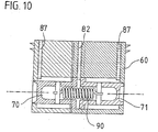
- the trained as a wire helix spring tension spring 90 is used in Essentially, already in - shown in Figure 10 - still not installed state of the pin 60, where so no Oil and thus no oil pressure in the pressure lines 82 and 87 rests, the two sliding pins 70 and 71 a Assign the idle state. So they can (70 and 71) during the Transport from the pin manufacturer to the vulcanization mold manufacturer do not rattle, do not tilt, do not mess up absorb the sealing sliding surfaces G, in short no damage to take.
- Each of the slidable bolts 70, 71 has an inward one deft piston-like surface Ki and an outward-facing Piston surface Ka on. After vulcanization of a tire the Inserting bolts 70, 71 back into pin 60 is provided to let oil flow in through the lines 87, so that this oil on the piston-like surfaces Ka the slidable pin 70 and 71 presses. At the same time should be oil flow out via the line 82.
- the two pressure oil lines 87 are made in the manner that in the housing part 61 and 62 each have a housing bore was then brought down and then in this ever a metal tube 88 was pressed, which down to something in the rounded cuboidal cavity 63, both Enclose housing parts 61 and 62, protrudes.
- This Supernatant of the tube 88 serves as a stop for the Outward movement of the bolts 70, 71.
- the pressurized oil passage 82 is made in the same manner as the two pressure oil lines 87, namely by in the Housing part 62 centered in the dovetail connection between the two housing parts 61 and 62 a Housing bore was drilled and then in this one Metal tube 88 was pressed. Also this metal tube 88 protrudes downwards slightly in the rounded cuboid Cavity 63. This supernatant of this tube 88 serves as a stop for the inward movement of the bolts 70, 71.
- the housing of the tandem pin 60 is in two housing parts 61st and 62 articulated, the detachable (as long as the pin is not in a vulcanization mold is installed) with each other via a Dovetail 66 are connected to the lowest possible Number of parts the mountability of the sliding bolt 70th and 71 and the spring 90 to reach.
- Both housing parts 60, 61 can be manufactured as a die-cast or forged part, preferably of a zinc or aluminum or steel alloy.
- both housing parts are identical.
- Dovetail interface between two housing parts 61, 62 would then form a flat surface, the middle Oil pressure channel in two equal, for example, milled, gutters divides.
- the two housing parts 61 and 62 would then be through to keep some through-bolts pressed together.
- higher number of parts would be such a construction cheaper because of a lower number of expensive non-standard ones Parts. The space utilization would be worse.
- the Anchoring such a pin in the rest of the segment should strengthen.
- the alloy of the pin housing parts 61, 62 should be tuned to the alloy of the rest of the segment be that the melting point of the pen housing parts is higher; so can such a prefabricated pin 60 with his ears 65 in the mold for the production of the molding segment used and then cast with, making a very safe combination of fabric and form-fitting is achievable.
- FIG. 9b shows the same pin 60 in a view looking along the main line of the cup row to be created herewith.
- the preferred rounded cuboid shape of the push-out bolt 70 this of course also applies to the - lying behind bolt 71.
- the cutting edge 73 is clearly visible and within the sink surfaces 74 and 75th
- FIG. 9 c shows the same tandem pin 60 in a top view. In this view, the seal between the two housing parts 61 and 62 can be seen particularly well.
- FIG. 10 is nearly identical to FIG. 9a; the only difference is that here the slidable pins 70, 71 are shown in their retracted state, that is to say in the state in which they are marketed for the realization of the invention essential products, referred to in this application as "pin 60" and should be transported. Because of the otherwise existing equality not all but only the most important reference numbers are given here. For the rest, reference is made to the explanations to the figures 9.
- Figures 11 show, on an enlarged scale, a pin of a different type, namely a single pin, which, for the sake of simplicity, is given the same reference numeral 60. It can be used in place of the previously explained tandem pin or for other cup traces in addition to a vulcanization mold analogous to Figure 8.
- the term "single” is intended to indicate that a pin 60 of this construction contains only a single slidable bolt 70.
- Figures 11 are drawn at the same scale as Figures 9 to facilitate comparisons.
- FIG. 11a shows a longitudinal section with a view transverse to the main line of hereby created Napokhe.
- the housing is here divided into a main part 67 - which is very similar to the housing part 61 or 62 of the embodiment according to the figures 9, but has neither a father nor a mother dovetail part - and a lid 68th
- the only sliding bolt here is constructed the same way like the left slidable bolt 70 in Figs. 9; therefore Here are the same reference numerals used.
- the single bolt 70 has a raised edge 72 with a razor-sharp edge 73 at its radially outermost edge. Radially inward, an oblique surface 74 connects, which together with the bottom surface 75 forms a depression 76.
- the sliding bolt 70 also has a depression 76 its front side as the opposing lid 68th
- the cover 68 is by soldering along the joining surface 69 in Housing part 67 anchored insoluble.
- the cavity 63, the to be moved piston surfaces Ki and Ka and the lid 68, or at least the lid 68 would be circular, then the Connection technology in a detachable fine thread pairing on the joint surface 69 exist, what an approach to the Interior of the pin for maintenance then also allow would, if this with his housing 67 and his ears 65th insoluble in a segment of a vulcanization mold, e.g. B. by casting, anchored.
- Drahthelixzugfeder 90 the sliding bolt 70th already in not installed condition of pin 60, where still no oil and thus no oil pressure in the pressure lines 82 and 87 is a resting position and indeed - so here is one Tensile and no compression spring, although the latter easier to mount would be - in the inserted position. This saves space and reduces the risk of injury to and at the sharp edge 73.
- the sliding bolt 70 has an inwardly facing piston-like surface Ki and an outwardly facing piston surface Ka up. To after vulcanization of a tire the bolt 70 back into the pin 60 in is provided, oil via the line 87 to flow, so that this oil the piston-like surface Ka of the slidable bolt 70 suppressed. At the same time, oil should flow out via line 82.
- the two pressure oil lines 82 and 87 are - as in the Embodiment according to FIGS. 9 - produced in the manner that in the housing part 67 each have a housing bore was then brought down and then in this ever a metal tube 88 was pressed, which down to something in the rounded cuboidal cavity 63, the housing part 67 and the lid 68 enclose, protruding.
- This supernatant the tube 88 serves as a stop for the movement of the Bolzens 70 and that the tube 88 in the bore 82 to Limiting the inward movement and the tube 88 in the Bore 87 for limiting the outward movement.
- Both housing parts 67 and 68 can as Druckguss- or Forged are produced, preferably from a zinc or Aluminum or steel alloy.
- Figure 11b shows the same single pen in the front view, ie a view with a view along the main line of the Napokhe to be created herewith. Because of the identity of the bolts 70 and the great similarity in the housing design, this figure is consistent with Figure 9b.
- FIG. 11c shows the same single pin in a plan view, that is, with a viewing direction-with respect to the tire to be manufactured-from radially outside to radially inside.
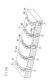
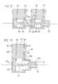
- FIG. 12 shows the series arrangement of two single pins 60, as already shown individually in FIG. 11a.
- the end face of the pushed-out pin 70 of the pin 60 shown on the left engages with the leading sharp edge 73 in the housing cover 68 of the right-hand adjacent pin 60 with respect to the ejection direction.
- the cooperation with the sharp edge 78a of the Housing cover 68 causes an efficient separation of thin rubber loops.
- the tire tread to be produced throws such fine severed cuticles with the help of the jolting vibrations and centrifugal forces through the cups after just a few kilometers of operation.
- a Vulcanization mold for belt-reinforced radial pneumatic tires consists usually from 7 to 25 such segments, in the circumferential direction connect to each other, as well as two side covers. Vulcanizing molds for solid tires can look almost identical; only there is at the - irrelevant for the invention - radially inner side an additional metal ring for shaping the inside of the tire required.
- FIG. 8 refers to a division into 24 equal segments.
- FIG. 13 shows a variant of the single-pin according to FIGS. 11 in a representation analogous to FIG. 11 a, but with a telescopic piston.
- the outer part 70b of this telescopic piston corresponds exactly to the piston 70 shown in Figure 12 and therefore does not need to be explained in detail.
- the inner part 70a of the telescopic piston has a substantially Z-shaped longitudinal section. Moreover, it has at least one oil passage 89, which allows the return of the outer piston part 70b.
- the back cover 68 is - apart from its larger Outer diameter - with the lid of Figures 11 and Figure 12 identical.
- telescopic pistons are also in tandem pens usable; this would only require the cover 68 to be removed and a second housing 67 inverted from the left against the Area 100 to be pressed and the four each other facing ears 65 to be removed. As already in the Related to Figures 9, this could be done by means of Through bolts are realized or - then but accepting the difference between the two Housing parts - by a dovetail connection.
- a certain difficulty in the production of a telescopic pen according to Figure 13 is in the pressure channel 89. With the So far, affordable manufacturing techniques are recommended Such a multi-membered construction only for use in such vulcanization molds, the tires of a tread depth of Emboss and vulcanize at least 20 mm profile depth. Such Races are used on off-road vehicles and trucks. With Treads of the invention to be expected lowering the rolling noise is particularly interesting there.
- the essence of the invention is that in one bowl having tread profile through the channels to channels Napeghen are connected, the cross-sectional area of Channels are significantly smaller than those of the bowls. Preferably enforce these channels only the profile reason, so not the Tread periphery.
- Such tires are in vulcanization forms It can be produced in shape during a tire heating process change twice.
- Such vulcanization forms contain nappr Weggende pins with sliding therein canal-forming bolt.
Landscapes
- Engineering & Computer Science (AREA)
- Mechanical Engineering (AREA)
- Moulds For Moulding Plastics Or The Like (AREA)
- Heating, Cooling, Or Curing Plastics Or The Like In General (AREA)
- Tires In General (AREA)
Abstract
- ein Laufflächenprofil für einen Fahrzeugreifen,
- eine Vulkanisierform als Vorrichtung zur Herstellung eines solchen Fahrzeugreifens mit einem erfindungsgemäßen Laufflächenprofil und auf
- einen Stift als Vorrichtung zur Herstellung eines erfindungsgemäßen Laufflächenprofiles und als Bestandteil einer Vulkanisierform.
Description
- ein Laufflächenprofil für einen Fahrzeugreifen gemäß dem Oberbegriff des Patentanspruches 1,
- eine Vulkanisationsform gemäß dem Oberbegriff des Patentanspruches 14 als Vorrichtung zur Herstellung eines solchen Fahrzeugreifens mit einem erfindungsgemäßen Laufflächenprofil und auf
- einen Stift gemäß dem Oberbegriff des Patentanspruches 6 als Vorrichtung zur Herstellung eines erfindungsgemäßen Laufflächenprofiles und als Bestandteil einer Vuikanisationsform nach Anspruch 14
- wobei jede Napfreihe (X, XI, XII, ... XIX) einen oder
mehrere Näpfe
(10a, 10b, 10c, 10d, ...;
11a, 11b, 11c, 11d, 11e; 11f;
12a, 12b, 12c, 12d, 12e, 12f;
...
19a, 19b, 19c, 19d) aufweist, - wobei ein jeder Napf (10a, 10b, ... 19c, 19d) ein Profilnegativ von einer Breite (b) oder Durchmesser (d) ist, die höchstens das 2-fache - bevorzugt etwa das 1,2-fache - der Profiltiefe (t) beträgt, wobei diese Breite (b) bzw. dieser Durchmesser (d) in der Ebene der Laufflächenperipherie senkrecht zur Hauptlinie (10, 11, 12, ..., 19) der jeweiligen Napfreihe (X, XI, XII, ..., XIII) zu messen ist,
- wobei die Länge (1) eines jeden Napfes (10a, 10b, ..., 19c, 19d) entlang der jeweiligen Hauptlinie (10, 11, ..., 19) höchstens das 4-fache - bevorzugt das 1,5-fache - der Profiltiefe (t) beträgt, und
- wobei die Tiefe (t) besagter Näpfe (10a, 10b, ..., 19c, 19d) etwa der üblichen Profiltiefe für die jeweilige Reifenkategorie entspricht. (Dabei soll "etwa" +/- 20% heißen.)
- die Näpfe (10a, 10b, ..., 19c, 19d), die zu einer Napfreihe (X, XI, ..., XIX) gehören, durch einen Kanal (20, 21, ..., 29) miteinander oder mit Profilrillen (7) oder mit einem Laufflächenrand verbunden sind,
- wobei die Querschnittsfläche eines jeden solchen Kanales (20, 21, ..., 29) zwischen 10 % und 50 % der Querschnittsfläche der jeweils anschließenden Näpfe (10a, 10b, ..., 19c, 19d) beträgt, wobei die Querschnittsflächen senkrecht zur Hauptlinie (10, 11, ..., 19) der jeweiligen Napfreihe (X, XI, ..., XIX) zu messen ist.
- dass es in an sich bekannter Weise Querrillen ( ) enthält und zusätzlich im Wesentlichen in Umfangsrichtung verlaufende Kanäle, die diese Querrillen kreuzen und nur unten in der Nähe der vollen Profiltiefe existieren, wobei an jeder Kreuzungsstelle zwischen einem solchen Kanal ( ) und einer solchen Querrille ( ) ein Napf angeordnet ist, oder
- dass es in an sich bekannter Weise Längsrillen ( ) enthält und zusätzlich im Wesentlichen in axialer oder diagonaler Richtung verlaufende Kanäle, die diese Längsrillen kreuzen und nur unten in der Nähe der vollen Profiltiefe existieren, wobei an jeder Kreuzungsstelle zwischen einem solchen Kanal ( ) und einer solchen Längsrille ( ) ein Napf angeordnet ist.
Die genannten Umschaltungen in der Ölförderrichtung können durch zwei separate Ölhochdruckpumpen ohne Umschaltventile verwirklicht werden oder durch eine einzige Ölhochdruckpumpe unter Zwischenschaltung von Umschaltventilen.
für leichte Motorräder bis ca. 125 ccm ca. 4 mm,
für mittelschwere Motorräder bis ca. 350 ccm ca. 5,5 mm,
für schwere Motorräder ca. 7 mm,
für PKW- und Transporter-Reifen ca. 8mm,
für Leicht-LKW-Reifen ca. 13 mm und für
schwere LKW-Reifen 15 bis zu ca. 18 mm
betragen. Diese Werte beziehen sich auf eine Verwendung der -Reifen auf befestigten Straßen. Für eine Verwendung der erfindungsgemäßen, entlüftete Näpfe enthaltenden Profile im Gelände empfehlen sich größere Napftiefen, und zwar - je nach Steilheit und Matschigkeit des Geländes - um bis zu 50 % größere Napftiefen.
- Figur 1
- maßstabsgerecht einen ersten Fahrzeugreifen mit einem erfindungsgemäßen Laufflächenprofil, das in der Mitte eine Napfreihe beinhaltet, wobei diese Näpfe alle miteinander durch in Umfangsrichtung verlaufende Kanäle verbunden sind,
- Figur 2
- maßstabsgerecht einen anderen Fahrzeugreifen, nämlich einen Fahrzeugluftreifen für PKW mit einem erfindungsgemäßen Laufflächenprofil, das ausschließlich Napfreihen beinhaltet und zwar im Laufflächenmittenbereich mehrere der Napfreihen, von denen Figur 1 bereits eine gezeigt hat und in beiden Schulterbereichen mehrere im Wesentlichen axial verlaufende Napfreihen mit verschiedenen Kanalausführungen zwischen diesen Näpfen,
- Figur 3
- maßstabsgerecht einen anderen Fahrzeugiuftreifen für PKW mit einem erfindungsgemäßen Laufflächenprofil, welches in beiden Schulterbereichen mit der Ausführung gemäß Figur 2 übereinstimmt, im Laufflächenmittenbereich jedoch im Wesentlichen axial ausgerichtete Napfreihen aufweist, die in drei konventionelle Umfangsrillen münden,
- Figur 4a
- in einem vergrößerten Maßstabe eine Periodenlänge eines äußeren Positivstreifens gemäß Figur 2 in einem Längsschnitt mit einer Blickrichtung von oben (=radial außen) und axial außen,
- Figur 4b
- in einem vergrößerten Maßstabe eine Periodenlänge eines äußeren Positivstreifens gemäß Figur 3 in einem Längsschnitt mit einer Blickrichtung von oben (=radial außen) und axial außen,
- Figur 5
- ausschnittsweise eine Abwicklung eines anderen erfindungsgemäßen Laufstreifenprofiles, bei dem eine Schar an sich bekannter Querrillen von einem in Umfangsrichtung verlaufenden, durchgehenden Strang aneinander anschließender Kanäle gekreuzt werden und an jeder Kreuzungsstelle je ein Napf angeordnet ist,
- Figur 6
- ausschnittsweise eine Abwicklung eines anderen erfindungsgemäßen Laufstreifenprofiles, bei dem zwei an sich bekannte Längsrillen von einer Schar in diagonaler Richtung verlaufender, durchgehender Stränge aneinander anschließender Kanäle gekreuzt werden und an jeder Kreuzungsstelle je ein Napf angeordnet ist,
- Figur 7
- ausschnittsweise eine Abwicklung eines anderen erfindungsgemäßen Laufstreifenprofiles mit vier an sich bekannten Längsrillen, wobei die beiden linken Längsrillen durch eine linke Schar diagonal verlaufender, durchgehender Stränge aneinander anschließender Kanäle mit dem linken Rand der Lauffläche verbunden sind und nur an den Kreuzungsstellen dieser Kanalstränge mit der ganz linken Umfangsrille je ein Napf angeordnet ist, und wobei die beiden rechten Längsrillen durch eine rechte Schar diagonal verlaufender, durchgehender Stränge aneinander anschließender Kanäle mit dem rechten Rand der Lauffläche verbunden sind und nur an den Kreuzungsstellen dieser Kanalstränge mit der ganz rechten Umfangsrille je ein Napf angeordnet ist,
- Figur 8
- einen Längsschnitt durch ein Segment einer radial geteilten, erfindungsgemäßen Vulkanisationsform zur Herstellung eines solchen erfindungsgemäßen Reifens, wie er in Figur 1 gezeigt ist, wobei die Schnittebene mitten durch das Segment und somit mitten durch die Stifte, die die zentrale Napfreihe erzeugen, verläuft,
- Figuren 9
- in größerem Maßstabe einen der in die Vulkanisationsform nach Figur 8 eingesetzten Tandem-Stifte mit je einem nach links (beispielsweise im Reifendrehsinn) und einem nach rechts (beispielsweise entgegen dem Reifendrehsinn) herausgeschobenen Bolzen, und zwar
- Figur 9a
- in einem Längsschnitt mit Blickrichtung quer zur Hauptlinie der hiermit zu erstellenden Napfreihe,
- Figur 9b
- in einer Ansicht mit Blickrichtung entlang der Hauptlinie der hiermit zu erstellenden Napfreihe, kurz eine Stirnansicht, und
- Figur 9c
- in einer Draufsicht.
- Figur 10
- in zur Figur 9a analogen Darstellungsweise den gleichen Tandemstift, jedoch mit beiden Bolzen im hereingeschobenen Zustande,
- Figuren 11
- einen Single-Stift mit einem einzigen verschiebbaren Bolzen, und zwar
- Figur 11a
- in einem Längsschnitt mit Blickrichtung quer zur Hauptlinie der hiermit zu erstellenden Napfreihe,
- Figur 11b
- in einer Ansicht mit Blickrichtung entlang der Hauptlinie der hiermit zu erstellenden Napfreihe, kurz eine Stirnansicht, und
- Figur 11c
- in einer Draufsicht,
- Figur 12
- eine Hintereinanderreihung von Single-Stiften gemäß Figur 11a zur Ausbildung langer oder gar endloser Stränge von Kanälen unterhalb der Reifenperipherie, und
- Figur 13
- eine Variante des Single-Stiftes nach den Figuren 11 in einer zur Figur 11a analogen Darstellung, jedoch mit einem Teleskop-Kolben.
- 1
- Fahrzeugvollreifen (Figur 1) oder Fahrzeugluftreifen (Figuren 2 und 3)
- 2
- Wülste von 1
- 3
- Seitenwände von 1
- 4
- profilierte Lauffläche von 1
- 5
- linke Umfangsrille in 4 gemäß Figur 1 oder Figur 6
- 6
- rechte Umfangsrille in 4 gemäß Figur 1 oder Figur 6
- 7
- linke Umfangsrille in 4 gemäß Figur 3
- 8
- rechte Umfangsrille in 4 gemäß Figur 3
- 9
- mittlere Umfangsrille in 4 gemäß Figur 3
- 10
- Hauptlinie der Napfreihe X (dick strichpunktiert in Figur 1)
- 10a
- Napf aus der Napfreihe X
- 10b
- Napf aus der Napfreihe X
- 10c
- Napf aus der Napfreihe X
- 10d
- Napf aus der Napfreihe X
- . . . 11
- Hauptlinie der Napfreihe XI (dick strichpunktiert in Figuren 4a und 4b)
- 11a
- Napf aus der Napfreihe XI (Figuren 2 und 3)
- . . . 11f
- Napf aus der Napfreihe XI (Figuren 2 und 3)
- 12
- Hauptlinie der Napfreihe XII (dick strichpunktiert in Figuren 4a und 4b)
- 12a
- Napf aus der Napfreihe XII (Figuren 4a und 4b)
- 12b
- Napf aus der Napfreihe XII (Figuren 4a und 4b)
- . . . 12f
- Napf aus der Napfreihe XII (Figuren 4a und 4b)
- 13
- Hauptlinie der Napfreihe XIII (dick strichpunktiert in Figuren 4a und 4b)
- 14
- Hauptlinie der Napfreihe XIV (dick strichpunktiert in Figuren 4a und 4b)
- 15
- Hauptlinie der Napfreihe XV (dick strichpunktiert in Figuren 4a und 4b)
- 16a
- Napf aus der Napfreihe XVI
- 16b
- Napf aus der Napfreihe XVI
- 16c
- Napf aus der Napfreihe XVI
- 16d
- Napf aus der Napfreihe XVI
- 17a
- Napf aus der Napfreihe XVII
- 17b
- Napf aus der Napfreihe XVII
- 17c
- Napf aus der Napfreihe XVII
- 18a
- Napf aus der Napfreihe XVIII
- 18b
- Napf aus der Napfreihe XVIII
- 18c
- Napf aus der Napfreihe XVIII
- 18d
- Napf aus der Napfreihe XVIII
- 19a
- Napf aus der Napfreihe XIX
- 19b
- Napf aus der Napfreihe XIX
- 19c
- Napf aus der Napfreihe XIX
- 19d
- Napf aus der Napfreihe XIX
- 20
- Kanäle zwischen Näpfen der Napfreihen X (dünn gestrichelt in einem Ausschnitt von Figur 2, der zwischen den beiden strichpunktierten Lupen VIa liegt)
- 21
- Kanäle zwischen Näpfen der Napfreihen XI (Figuren 4a und 4b ganz rechts)
- 22
- Kanäle zwischen Näpfen der Napfreihen XII (Figuren 4a und 4b zweite.von rechts)
- 23
- Kanäle zwischen Näpfen der Napfreihen XIII (Figuren 4a und 4b mitte)
- 24
- Kanäle zwischen Näpfen der Napfreihen XIV (Figuren 4a und 4b zweite von links)
- 25
- Kanäle zwischen Näpfen der Napfreihen XV (Figuren 4a und 4b ganz links)
- 26
- Kanäle zwischen Näpfen der Napfreihen XVI (Figuren 4a und 4b ganz links)
- 27
- in Umfangsrichtung verlaufende, aneinander anschließende Kanäle, die 30 kreuzen (Figur 5)
- 28
- in diagonaler Richtung verlaufende, innerhalb von Strängen aneinander anschließende Kanäle, die Umfangsrille(n) kreuzen (nämlich 5 und 6 in Figur 6 und 40 in Figur 7)
- 29
- in diagonaler Richtung verlaufende, innerhalb von Strängen aneinander anschließende Kanäle, die Umfangsrille(n) kreuzen (nämlich 43 in Figur 7)
- 30
- an sich bekannte Querrillen 30 (Figur 5)
- 40
- ganz links angeordnete Längsrille (Figur 7)
- 41
- rechts von 40 angeordnete Längsrille (Figur 7)
- 42
- links von 43 angeordnete Längsrille (Figur 7)
- 43
- ganz rechts angeordnete Längsrille (Figur 7)
- 50
- Segment einer radial geteilten, erfindungsgemäßen Vulkanisationsform zur Herstellung erfindungsgemäßer Reifen 1
- 60
- Stifte (egal ob Tandem- oder Single-Stift) in Vulkanisationsform 50 zur Erzeugung von Näpfen in 1
- 61
- linkes Gehäuseteil von Tandem-Stift 60
- 62
- rechtes Gehäuseteil von Tandem-Stift 60
- 63
- Hohlraum, den 61 und 62 umschließen, vorzugsweise gerundet quaderförmig
- 64
- Dichtungen zwischen 61 und 62
- 65
- Ohren zur Verankerung von 60 in 50
- 66
- Schwalbenschwanz zur Zusammenfügung von 61 und 62
- 67
- Hauptgehäuseteil für Single-Stift 60
- 68
- Gehäusedeckel von 67
- 69
- Fügefläche (gezeigt als Lötverbindung) zwischen 67 und 68
- 70
- heraus- und hereinschiebbare Bolzen von 60 mit Mutterschneide
- 70a
- axial inneres (und damit radial äußeres), verschiebliches, hülsenförmiges Teil von Z-förmigem Längsschnitt als Bestandteil eines Teleskop-Bolzens
- 70b
- axial äußerer (und damit radial innerer), verschiebbarer Teil von Teleskop-Bolzen; vorzugsweise identisch mit 70
- 71
- heraus- und hereinschiebbare Bolzen von 60 mit Vaterschneide
- 72
- erhabener Rand von 70
- 73
- messerscharfe Kante an 72
- 74
- schräge - vorzugsweise innenpyramidische - Fläche, die sich nach radial innen hin an 73 anschließt
- 75
- plane Fläche an Stirnseite von 70
- 76
- Senke in Stirnseite von 70 und 71
- 77
- erhabener Rand von 71
- 78
- messerscharfe Kante an 77
- 78a
- messerscharfe Kante an 68
- 79
- schräge - vorzugsweise außenpyramidische - Fläche, die sich nach radial außen hin an 78 anschließt
- 80
- zentraler Öldruckkanal in 50; leitet Öl in 81 und dient der Herausschiebung von 70
- 81
- Verbindungs- oder Verteilungsleitung in 50; verbindet 80 mit 82; dient der Herausschiebung von 70
- 82
- innerhalb von 60 ausgebildeter Öldruckkanal; leitet Öl zu den nach innen gewandten Kolbenflächen und dient somit der Herausschiebung von 70
- 85
- zentraler Öldruckkanal in 50; leitet Öl in 86 und dient der Hereinschiebung von 70
- 86
- Verbindungs- oder Verteilungsleitung in 50; verbindet 85 mit 87; dient der Hereinschiebung von 70
- 87
- innerhalb von 60 ausgebildeter Öldruckkanal (Figuren 11, 12 und 13) bzw. Öldruckkanäle (Figuren 8, 9 und 10); leitet Öl zu den nach innen gewandten Kolbenflächen und dient somit der Hereinschiebung von 70
- 88
- Metallröhrchen, das 82 und 87 auskleidet
- 89
- Öldruckkanal durch 70a
- 90
- Rückstellfeder
- 91
- Querbolzen zur Aufhängung von 90 in 70 und 71
- 92
- Querbolzen zur Aufhängung von 90 in 68
- 100
- rückwärtige (das heißt der Ausschiebeöffnung gegenüber liegende) Wand des Gehäuses 67 eines Single-Stiftes 60
- X
- in Umfangsrichtung verlaufende Napfreihe mit rechteckförmigen Näpfen, die jeweils durch einen Kanal von im Wesentlichen rechteckförmigem Querschnitt miteinander verbunden- sind, der nur im Bereich des Profilgrundes existiert (Figuren 1 und 2)
- XI
- Napfreihe analog X, jedoch im Wesentlichen axial verlaufend (Figuren 2 und 3, détailliert in Figur 4a bzw. Figur 4b)
- XII
- im Wesentlichen axial verlaufende Napfreihe mit Näpfen von kreisförmiger Draufsicht, die durch einen Kanal von im Wesentlichen schlüssellochförmigem Querschnitt miteinander verbunden sind, wobei die Kanäle an der Laufflächenperipherie enger sind als im Profilgrunde (Figuren 2 und 3, détailliert in Figur 4a bzw. Figur 4b)
- XIII
- im Wesentlichen axial verlaufende Napfreihe mit in der Draufsicht rechteckförmigen Näpfen, die durch einen Kanal von im Wesentlichen trapezförmigem Querschnitt miteinander verbunden sind, wobei die Kanäle an der Laufflächenperipherie enger sind als im Profilgrunde (Figuren 2 und 3, detailliert in Figur 4a bzw. Figur 4b)
- XIV
- im Wesentlichen axial verlaufende Napfreihe mit in der Draufsicht sechseckförmigen Näpfen, die durch einen Kanal von im Wesentlichen trapezförmigem miteinander verbunden sind, wobei die Kanäle an der Laufflächenperipherie enger sind als im Profilgrunde (Figuren 2 und 3, détailliert in Figur 4a bzw. Figur 4b)
- XV
- im Wesentlichen axial verlaufende Napfreihe mit in der Draufsicht rechteckförmigen Näpfen, die durch einen Kanal miteinander verbunden sind, wobei die Kanäle an der Laufflächenperipherie etwa genauso weit sind wie im Profilgrunde (Figuren 2 und 3, détailliert in Figur 4a bzw. Figur 4b)
- XVI
- im Laufflächenmittenbereich zwischen je zwei Umfangsrillen 7-9 oder 9-8 angeordnete und in diese beidseitig mündende, im Wesentlichen axial verlaufende Napfreihe mit in der Draufsicht kreisförmigen Näpfen, die durch einen Kanal von trapezförmigem Querschnitt miteinander verbunden sind, wobei die Kanäle an der Laufflächenperipherie enger sind als im Profilgrunde (Figur 3)
- XVII
- Napfreihe an Kreuzungsstellen zwischen 27 und 30 (Figur 5)
- XVIII
- Napfreihe an Kreuzungsstelle zwischen 28 und 5 in Figur 6 bzw. zwischen 28 und 40 in Figur 7
- XIX
- Napfreihe an Kreuzungsstelle zwischen 28 und 6 in Figur 6 bzw. zwischen 28 und 43 in Figur 7
- G
- Gleitflächen von 70 und 71
Claims (14)
- Laufflächenprofil für einen Fahrzeugreifen (1)dadurch gekennzeichnet,mit einer oder mehreren Napfreihen (X und/oder XI, XII, XIII, XIV, XV und/oder XVI, XVII, XVIII, XIX)wobei jede Napfreihe (X, XI, XII, ..., XIX) einen oder mehrere Näpfe
(10a, 10b, 10c, 10d, ... ;
11a, 11b, 11c, 11d, 11e; 11f;
12a, 12b, 12c, 12d, 12e, 12f
19a, 19b, 19c, 19d) aufweist,wobei ein jeder Napf (10a, 10b, ... 19c, 19d) ein Profilnegativ von einer Breite (b) oder Durchmesser (d) ist, die höchstens das 2-fache - bevorzugt etwa das 1,2-fache - der Profiltiefe (t) beträgt, wobei diese Breite (b) bzw. dieser Durchmesser (d) in der Ebene der Laufflächenperipherie senkrecht zur Hauptlinie (10, 11, 12, ..., 19) der jeweiligen Napfreihe (X, XI, XII, ..., XIX) zu messen ist,wobei die Länge (1) eines jeden Napfes (10a, 10b, ... 19c, 19d) entlang der jeweiligen Hauptlinie (10, 11, ..., 19) höchstens das 4-fache - bevorzugt etwa das 1,5-fache - der Profiltiefe (t) beträgt,wobei die Tiefe (t) besagter Näpfe (10a, 10b, ..., 19c, 19d) etwa der üblichen Profiltiefe für die jeweilige Reifenkategorie entspricht,dass-die Näpfe (10a, 10b, ..., 19c, 19d), die zu einer Napfreihe (X, XI, ..., XIX) gehören, durch einen Kanal (20, 21, ..., 29) miteinander oder mit Profilrillen (7) oder mit einem Laufflächenrand verbunden sind,wobei die Querschnittsfläche eines jeden solchen Kanales (20, 21, ..., 29) zwischen 10 % und 50 % der Querschnittsfläche der jeweils anschließenden Näpfe (10a, 10b, ..., 19c, 19d) beträgt, wobei die Querschnittsflächen senkrecht zur Hauptlinie (10, 11, ..., 19) der jeweiligen Napfreihe (X, XI, ..., XIX) zu messen ist. - Laufflächenprofil nach Anspruch 1, dadurch gekennzeichnet, dass die Tiefe (t) der Näpfe (10a, 10b, ... 19c, 19d) bei Verwendung an Reifen
für leichte Motorräder bis ca. 125 ccm ca. 4 mm,
für mittelschwere Motorräder bis ca. 350 ccm ca. 5,5 mm,
für schwere Motorräder ca. 7 mm,
für PKW- und Transporter-Reifen ca. 8mm,
für Leicht-LKW-Reifen ca. 13 mm und für schwere LKW-Reifen 15 bis zu ca. 18 mm beträgt. - Laufflächenprofil nach einem der vorangehenden Ansprüche,
dadurch gekennzeichnet, dass der Kanal
(20 beziehungsweise 21 beziehungsweise ... beziehungsweise 29),
der die Näpfe (10a, 10b, 10c, 10d, ...
beziehungsweise 11a, 11b, 11c, 11d, 11e und 11f;
beziehungsweise ...
beziehungsweise 19a, 19b, 19c, 19d)
einer Napfreihe
(X beziehungsweise XI beziehungsweise ... beziehungsweise XIX)
miteinander oder mit Näpfen (18a, 18b, 18c, 18d) anderer Reihen oder mit den Laufflächenrändern verbindet,
unten, also in der Nähe der vollen Profiltiefe, eine größere Breite (Bu) aufweist als oben (Bo), also in der Nähe der Peripherie der profilierten Lauffläche. - Laufflächenprofil nach einem der vorangehenden Ansprüche,
dadurch gekennzeichnet, dass der Kanal
(20 beziehungsweise 21 beziehungsweise ... beziehungsweise 29),
der die Näpfe (10a, 10b, 10c, 10d, ...
beziehungsweise 11a, 11b, 11c, 11d, 11e und 11f; beziehungsweise ...
beziehungsweise 19a, 19b, 19c, 19d)
einer Napfreihe
(X beziehungsweise XI beziehungsweise ... beziehungsweise XIX)
miteinander oder mit Näpfen (18a, 18b, 18c, 18d) anderer Reihen oder mit den Laufflächenrändern verbindet, nur unten, also in der Nähe der vollen Profiltiefe, existiert,
wohingegen oben, also in der Nähe der Peripherie der profilierten Lauffläche, die Näpfe einer Napfreihe als voneinander isoliert, also als Sacknegative erscheinen. - Laufflächenprofil nach Anspruch 4, dadurch gekennzeichnet,dass es in an sich bekannter Weise Querrillen (30) enthält und zusätzlich im Wesentlichen in Umfangsrichtung verlaufende Kanäle (27), die diese Querrillen (30) kreuzen und nur unten in der Nähe der vollen Profiltiefe existieren, wobei zumindest an einigen Kreuzungsstellen zwischen einem solchen Kanal (27) und einer solchen Querrille (30) ein Napf (17a, 17b, 17c) angeordnet ist, oderdass es in an sich bekannter Weise Längsrillen (5, 6 ) enthält und zusätzlich im Wesentlichen in axialer oder diagonaler Richtung verlaufende Kanäle (28), die diese Längsrillen kreuzen und nur unten in der Nähe der vollen Profiltiefe existieren, wobei zumindest an einigen Kreuzungsstellen zwischen einem solchen Kanal (28) und einer solchen Längsrille (5, 6) ein Napf angeordnet ist.
- Stift (60) als Vorrichtung zur Herstellung eines Laufflächenprofiles nach Anspruch 3 oder 4 oder 5,
wobei der Stift (60) in eine Vulkanisierform (50) fest einsetzbar ist, z. B. durch Umgießen oder durch eine Schraubverbindung,
wobei der Stift (60) zur Abformung eines Napfes (10a oder 10b oder ... 19c oder 19d) dient,
dadurch gekennzeichnet, dass der Stift (60) in dem Bereich, der einen Napf eines Laufflächenprofiles in der Nähe der vollen Profiltiefe ausbilden soll, zumindest einen Bolzen (70 oder 71) aufweist, der verschieblich ist. - Stift nach Anspruch 6, dadurch gekennzeichnet, dass der Bolzen (70) mehrteilig ausgeführt ist, wobei seine Teile (70a, 70b) teleskopartig gegeneinander verschieblich sind.
- Stift (60) [Tandem-Stift] nach Anspruch 6 oder 7, dadurch gekennzeichnet, dass der Stift (60) in dem Bereich, der den Napf in der Nähe der vollen Profiltiefe ausbilden soll, zumindest zwei Bolzen (70, 71) aufweist, die verschieblich sind, und zwar der eine in die eine Orientierung und der andere entlang der gleichen Geraden, jedoch in der entgegengesetzten Orientierung.
- Stift (60) nach Anspruch 8, dadurch gekennzeichnet, dass zumindest einer (70) der beiden entgegengesetzt quer aus dem Stift (60) heraus schiebbaren Bolzen (70, 71) auf seiner beim Ausschieben voreilenden Stirnfläche einen erhabenen, scharfkantigen Rand (72) aufweist, der eine Senke (76) umgibt.
- Stift (60) nach Anspruch 9, dadurch gekennzeichnet, dass der eine (70) der beiden entgegengesetzt aus dem Stift (60) heraus schiebbaren Bolzen (70, 71) auf seiner beim Ausschieben voreilenden Stirnfläche einen Durchmesser aufweist, der größer als als der Innendurchmesser des erhabenen, scharfkantigen Randes (77) an dessen scharfer Kante (78) des anderen Bolzens (71) aber höchstens genauso groß wie der größte Außendurchmesser dieses anderen Bolzens (71).
- Stift (60) [Single-Stift] nach einem der Ansprüche 6 oder 7, jedoch nicht nach Anspruch 8, dadurch gekennzeichnet, dass er (60) zumindest an der voreilenden Stirnfläche des einen aus dem Stift (60) heraus schiebbaren Bolzens (70) oder an der der Bolzenaustrittsöffnung gegenüber liegenden Wandfläche (68) einen erhabenen, scharfkantigen Rand (72, 78a) aufweist, der eine Senke (76) umgibt.
- Stift nach Anspruch 11, dadurch gekennzeichnet, dass er (60) an der anderen Flächealso an der der Bolzenaustrittsöffnung gegenüber liegenden Wandfläche (68) beziehungsweise an der voreilenden Stirnfläche des einen aus dem Stift (60) heraus schiebbaren Bolzens (70) -
einen Durchmesser aufweist, der genauso groß oder geringfügig kleiner ist, wie bzw. als der Innendurchmesser des erhabenen, scharfkantigen Randes (78a) an der voreilenden Stirnfläche des Bolzens (70) beziehungsweise an der der Bolzenaustrittsöffnung gegenüber liegenden Wandfläche. - Stift nach einem der vorangehenden Ansprüche 6 bis 12,
dadurch gekennzeichnet, dass die Bolzen (70, 71) hydraulisch verschiebbar sind. - Vulkanisationsform zur Herstellung eines Fahrzeugreifens mit einem Laufflächenprofil nach zumindest einem der Ansprüche 1 bis 5,
dadurch gekennzeichnet, dass sie zumindest einen Stift (60) nach einem der Ansprüche 6 bis 13 enthält.
Applications Claiming Priority (2)
| Application Number | Priority Date | Filing Date | Title |
|---|---|---|---|
| DE10133430A DE10133430A1 (de) | 2001-07-10 | 2001-07-10 | Lauflächenprofil für einen Fahrzeugreifen, Stift als Vorrichtung zur Herstellung eines solchen Laufflächenprofiles und Vulkanisationform mit einem solchen Stift |
| DE10133430 | 2001-07-10 |
Publications (3)
| Publication Number | Publication Date |
|---|---|
| EP1275527A2 true EP1275527A2 (de) | 2003-01-15 |
| EP1275527A3 EP1275527A3 (de) | 2003-01-29 |
| EP1275527B1 EP1275527B1 (de) | 2005-02-09 |
Family
ID=7691246
Family Applications (1)
| Application Number | Title | Priority Date | Filing Date |
|---|---|---|---|
| EP02013037A Expired - Lifetime EP1275527B1 (de) | 2001-07-10 | 2002-06-13 | Laufflächenprofil für einen Fahrzeugreifen, Stift als Vorrichtung zur Herstellung eines solchen Laufflächenprofils und Vulkanisationsform mit einem solchen Stift |
Country Status (2)
| Country | Link |
|---|---|
| EP (1) | EP1275527B1 (de) |
| DE (2) | DE10133430A1 (de) |
Cited By (14)
| Publication number | Priority date | Publication date | Assignee | Title |
|---|---|---|---|---|
| EP1595673A1 (de) * | 2004-05-10 | 2005-11-16 | Société de Technologie MICHELIN | Method of manufacturing a tyre tread |
| FR2891489A1 (fr) * | 2005-10-04 | 2007-04-06 | Michelin Soc Tech | Moule pour bande de roulement de pneumatique. |
| EP1935602A1 (de) * | 2006-12-21 | 2008-06-25 | The Goodyear Tire & Rubber Company | Flexible Formvorrichtung zur Herstellung einer Senknut in einem Reifenprofil |
| EP1935601A1 (de) * | 2006-12-21 | 2008-06-25 | The Goodyear Tire & Rubber Company | Flexible Formvorrichtung zur Herstellung einer Senknut in einem Reifenprofil |
| EP1938956A1 (de) * | 2006-12-21 | 2008-07-02 | The Goodyear Tire & Rubber Company | Flexible Formvorrichtung zur Herstellung einer Senknut oder einer Oberflächenverbindungsstange in einem Reifenprofil |
| EP2070729A1 (de) * | 2004-12-28 | 2009-06-17 | The Goodyear Tire & Rubber Company | Luftreifen mit einem verbesserten Steg |
| WO2013083610A1 (fr) * | 2011-12-09 | 2013-06-13 | Compagnie Generale Des Etablissements Michelin | Combinaison d'une structure de pneu poids lourd avec une sculpture de bande de roulement |
| US8640751B2 (en) | 2007-09-26 | 2014-02-04 | Toyo Tire & Rubber Co., Ltd. | Pneumatic tire with tread having sipes |
| EP3153332A1 (de) * | 2015-10-06 | 2017-04-12 | Sumitomo Rubber Industries, Ltd. | Luftloser reifen |
| CN108290462A (zh) * | 2015-11-24 | 2018-07-17 | 株式会社普利司通 | 充气轮胎 |
| JP2019135124A (ja) * | 2018-02-05 | 2019-08-15 | 住友ゴム工業株式会社 | タイヤ |
| US10717248B2 (en) | 2013-08-30 | 2020-07-21 | Compagnie Generale Des Etablissements Michelin | Methods for forming a retreaded tire |
| CN111660734A (zh) * | 2019-03-06 | 2020-09-15 | 特耐橡胶工业有限公司 | 具有胎面排气沟之轮胎 |
| EP4331866A1 (de) * | 2022-08-31 | 2024-03-06 | Jose Maria Fernandez Garcia | Lauffläche mit traktionskettenwirkung |
Families Citing this family (2)
| Publication number | Priority date | Publication date | Assignee | Title |
|---|---|---|---|---|
| DE102006058086B4 (de) * | 2006-12-09 | 2014-07-03 | Continental Reifen Deutschland Gmbh | Fahrzeugluftreifen |
| IT202100002834A1 (it) * | 2021-02-09 | 2022-08-09 | Bridgestone Europe Nv Sa | Pneumatico per veicoli pesanti |
Family Cites Families (8)
| Publication number | Priority date | Publication date | Assignee | Title |
|---|---|---|---|---|
| DE183380C (de) * | ||||
| US1386513A (en) * | 1920-01-02 | 1921-08-02 | Henry M Lambert | Tire-mold |
| US1604450A (en) * | 1924-11-26 | 1926-10-26 | Lambert Tire & Rubber Co | Tire-constructing mold |
| GB251851A (en) * | 1925-10-05 | 1926-05-13 | Wallace Rosche Gillam | Tire mold |
| GB751641A (en) * | 1954-03-16 | 1956-07-04 | Ernest Roland Fenton | Improvements in or relating to pneumatic tyres |
| GB2061837A (en) * | 1979-10-31 | 1981-05-20 | Dunlop Ltd | Tyre treads |
| FR2548097A1 (fr) * | 1983-06-16 | 1985-01-04 | Michelin & Cie | Bande de roulement pour pneumatique et pour bandage elastique |
| US5924464A (en) * | 1996-03-29 | 1999-07-20 | Michelin Recherche Et Technique, S.A. | Tire having flow isolating grooves |
-
2001
- 2001-07-10 DE DE10133430A patent/DE10133430A1/de not_active Withdrawn
-
2002
- 2002-06-13 EP EP02013037A patent/EP1275527B1/de not_active Expired - Lifetime
- 2002-06-13 DE DE50202198T patent/DE50202198D1/de not_active Expired - Lifetime
Cited By (22)
| Publication number | Priority date | Publication date | Assignee | Title |
|---|---|---|---|---|
| EP1595673A1 (de) * | 2004-05-10 | 2005-11-16 | Société de Technologie MICHELIN | Method of manufacturing a tyre tread |
| EP2070729A1 (de) * | 2004-12-28 | 2009-06-17 | The Goodyear Tire & Rubber Company | Luftreifen mit einem verbesserten Steg |
| FR2891489A1 (fr) * | 2005-10-04 | 2007-04-06 | Michelin Soc Tech | Moule pour bande de roulement de pneumatique. |
| WO2007039623A1 (fr) * | 2005-10-04 | 2007-04-12 | Société de Technologie Michelin | Moule pour bande de roulement de pneumatique. |
| US7338269B2 (en) | 2005-10-04 | 2008-03-04 | Michelin Recherche Et Technique S.A. | Tire tread mold |
| US7575424B2 (en) | 2006-12-21 | 2009-08-18 | The Goodyear Tire & Rubber Company | Flexible molding device for manufacturing a sunken groove in a tire tread |
| US7544054B2 (en) | 2006-12-21 | 2009-06-09 | The Goodyear Tire & Rubber Company | Flexible molding device for manufacturing a sunken groove in a tire tread |
| US7544053B2 (en) | 2006-12-21 | 2009-06-09 | The Goodyear Tire And Rubber Company | Flexible molding device for manufacturing a sunken groove or surface tie bar in a tire tread |
| EP1935601A1 (de) * | 2006-12-21 | 2008-06-25 | The Goodyear Tire & Rubber Company | Flexible Formvorrichtung zur Herstellung einer Senknut in einem Reifenprofil |
| EP1935602A1 (de) * | 2006-12-21 | 2008-06-25 | The Goodyear Tire & Rubber Company | Flexible Formvorrichtung zur Herstellung einer Senknut in einem Reifenprofil |
| EP1938956A1 (de) * | 2006-12-21 | 2008-07-02 | The Goodyear Tire & Rubber Company | Flexible Formvorrichtung zur Herstellung einer Senknut oder einer Oberflächenverbindungsstange in einem Reifenprofil |
| US8640751B2 (en) | 2007-09-26 | 2014-02-04 | Toyo Tire & Rubber Co., Ltd. | Pneumatic tire with tread having sipes |
| WO2013083610A1 (fr) * | 2011-12-09 | 2013-06-13 | Compagnie Generale Des Etablissements Michelin | Combinaison d'une structure de pneu poids lourd avec une sculpture de bande de roulement |
| FR2983779A1 (fr) * | 2011-12-09 | 2013-06-14 | Michelin Soc Tech | Combinaison d'une structure de pneu poids lourd avec une sculpture de bande de roulement |
| US9981506B2 (en) | 2011-12-09 | 2018-05-29 | Compagnie Generale Des Etablissements Michelin | Combination of a heavy goods vehicle tire structure with a tread pattern |
| US10717248B2 (en) | 2013-08-30 | 2020-07-21 | Compagnie Generale Des Etablissements Michelin | Methods for forming a retreaded tire |
| EP3153332A1 (de) * | 2015-10-06 | 2017-04-12 | Sumitomo Rubber Industries, Ltd. | Luftloser reifen |
| US10252578B2 (en) | 2015-10-06 | 2019-04-09 | Sumitomo Rubber Industries, Ltd. | Non-pneumatic tire |
| CN108290462A (zh) * | 2015-11-24 | 2018-07-17 | 株式会社普利司通 | 充气轮胎 |
| JP2019135124A (ja) * | 2018-02-05 | 2019-08-15 | 住友ゴム工業株式会社 | タイヤ |
| CN111660734A (zh) * | 2019-03-06 | 2020-09-15 | 特耐橡胶工业有限公司 | 具有胎面排气沟之轮胎 |
| EP4331866A1 (de) * | 2022-08-31 | 2024-03-06 | Jose Maria Fernandez Garcia | Lauffläche mit traktionskettenwirkung |
Also Published As
| Publication number | Publication date |
|---|---|
| DE50202198D1 (de) | 2005-03-17 |
| EP1275527B1 (de) | 2005-02-09 |
| DE10133430A1 (de) | 2003-01-23 |
| EP1275527A3 (de) | 2003-01-29 |
Similar Documents
| Publication | Publication Date | Title |
|---|---|---|
| EP1275527A2 (de) | Laufflächenprofil für einen Fahrzeugreifen, Stift als Vorrichtung zur Herstellung eines solchen Laufflächenprofils und Vulkanisationsform mit einem solchen Stift | |
| EP3334612B1 (de) | Fahrzeugluftreifen | |
| EP0434967B1 (de) | Laufflächenprofil für Fahrzeugreifen | |
| DE60305030T2 (de) | Skalierbarer laufstreifen | |
| EP3256334B1 (de) | Fahrzeugluftreifen | |
| EP3208113B1 (de) | Fahrzeugluftreifen | |
| DE102014210823A1 (de) | Fahrzeugluftreifen | |
| EP3388256A1 (de) | Fahrzeugluftreifen | |
| DE2934142A1 (de) | Luftreifen | |
| EP3204243B1 (de) | Fahrzeugluftreifen | |
| EP2864137B1 (de) | Laufstreifenprofil eines fahrzeugreifens | |
| WO2007028466A1 (de) | Kolben für eine brennkraftmaschine | |
| DE60213445T2 (de) | Reifenlauffläche | |
| DE102013205908A1 (de) | Minuten-Kolbenring mit einer Rille | |
| DE102018217712A1 (de) | Fahrzeugluftreifen | |
| EP3009276B1 (de) | Fahrzeugluftreifen | |
| EP2376297B1 (de) | Fahrzeugluftreifen | |
| EP3659825A1 (de) | Fahrzeugluftreifen | |
| EP3560735B1 (de) | Nutzfahrzeugreifen | |
| EP1190871B1 (de) | Fahrzeugreifen mit Feineinschnitt in der Lauffläche, Vulkanisationsform zur Herstellung eines solchen Reifens und Lamelle zum Einsetzen in eine solche Vulkanisationsform | |
| EP4244082B1 (de) | Fahrzeugluftreifen | |
| EP4688463A1 (de) | Fahrzeugluftreifen | |
| EP3831619A1 (de) | Fahrzeugluftreifen | |
| EP2353886B1 (de) | Laufstreifenprofil eines Fahrzeugsreifens | |
| EP1586783A2 (de) | Hydraulikzylinder, insbesondere Geberzylinder für eine hydraulische Kupplungsbetätigung für Kraftfahrzeuge |
Legal Events
| Date | Code | Title | Description |
|---|---|---|---|
| PUAI | Public reference made under article 153(3) epc to a published international application that has entered the european phase |
Free format text: ORIGINAL CODE: 0009012 |
|
| PUAL | Search report despatched |
Free format text: ORIGINAL CODE: 0009013 |
|
| AK | Designated contracting states |
Kind code of ref document: A2 Designated state(s): AT BE CH CY DE DK ES FI FR GB GR IE IT LI LU MC NL PT SE TR |
|
| AX | Request for extension of the european patent |
Free format text: AL;LT;LV;MK;RO;SI |
|
| AK | Designated contracting states |
Designated state(s): AT BE CH CY DE DK ES FI FR GB GR IE IT LI LU MC NL PT SE TR |
|
| AX | Request for extension of the european patent |
Extension state: AL LT LV MK RO SI |
|
| 17P | Request for examination filed |
Effective date: 20030729 |
|
| AKX | Designation fees paid |
Designated state(s): DE FR GB IT |
|
| 17Q | First examination report despatched |
Effective date: 20031009 |
|
| GRAP | Despatch of communication of intention to grant a patent |
Free format text: ORIGINAL CODE: EPIDOSNIGR1 |
|
| GRAS | Grant fee paid |
Free format text: ORIGINAL CODE: EPIDOSNIGR3 |
|
| GRAA | (expected) grant |
Free format text: ORIGINAL CODE: 0009210 |
|
| AK | Designated contracting states |
Kind code of ref document: B1 Designated state(s): DE FR GB IT |
|
| PG25 | Lapsed in a contracting state [announced via postgrant information from national office to epo] |
Ref country code: IT Free format text: LAPSE BECAUSE OF FAILURE TO SUBMIT A TRANSLATION OF THE DESCRIPTION OR TO PAY THE FEE WITHIN THE PRESCRIBED TIME-LIMIT;WARNING: LAPSES OF ITALIAN PATENTS WITH EFFECTIVE DATE BEFORE 2007 MAY HAVE OCCURRED AT ANY TIME BEFORE 2007. THE CORRECT EFFECTIVE DATE MAY BE DIFFERENT FROM THE ONE RECORDED. Effective date: 20050209 Ref country code: GB Free format text: LAPSE BECAUSE OF FAILURE TO SUBMIT A TRANSLATION OF THE DESCRIPTION OR TO PAY THE FEE WITHIN THE PRESCRIBED TIME-LIMIT Effective date: 20050209 |
|
| REG | Reference to a national code |
Ref country code: GB Ref legal event code: FG4D Free format text: NOT ENGLISH |
|
| REG | Reference to a national code |
Ref country code: IE Ref legal event code: FG4D Free format text: GERMAN |
|
| REF | Corresponds to: |
Ref document number: 50202198 Country of ref document: DE Date of ref document: 20050317 Kind code of ref document: P |
|
| GBV | Gb: ep patent (uk) treated as always having been void in accordance with gb section 77(7)/1977 [no translation filed] |
Effective date: 20050209 |
|
| PLBE | No opposition filed within time limit |
Free format text: ORIGINAL CODE: 0009261 |
|
| STAA | Information on the status of an ep patent application or granted ep patent |
Free format text: STATUS: NO OPPOSITION FILED WITHIN TIME LIMIT |
|
| 26N | No opposition filed |
Effective date: 20051110 |
|
| ET | Fr: translation filed | ||
| REG | Reference to a national code |
Ref country code: FR Ref legal event code: PLFP Year of fee payment: 14 |
|
| PGFP | Annual fee paid to national office [announced via postgrant information from national office to epo] |
Ref country code: FR Payment date: 20150619 Year of fee payment: 14 |
|
| REG | Reference to a national code |
Ref country code: FR Ref legal event code: ST Effective date: 20170228 |
|
| PG25 | Lapsed in a contracting state [announced via postgrant information from national office to epo] |
Ref country code: FR Free format text: LAPSE BECAUSE OF NON-PAYMENT OF DUE FEES Effective date: 20160630 |
|
| PGFP | Annual fee paid to national office [announced via postgrant information from national office to epo] |
Ref country code: DE Payment date: 20190630 Year of fee payment: 18 |
|
| REG | Reference to a national code |
Ref country code: DE Ref legal event code: R119 Ref document number: 50202198 Country of ref document: DE |
|
| PG25 | Lapsed in a contracting state [announced via postgrant information from national office to epo] |
Ref country code: DE Free format text: LAPSE BECAUSE OF NON-PAYMENT OF DUE FEES Effective date: 20210101 |