EP1275480A2 - Panel of sheet material - Google Patents
Panel of sheet material Download PDFInfo
- Publication number
- EP1275480A2 EP1275480A2 EP20020396113 EP02396113A EP1275480A2 EP 1275480 A2 EP1275480 A2 EP 1275480A2 EP 20020396113 EP20020396113 EP 20020396113 EP 02396113 A EP02396113 A EP 02396113A EP 1275480 A2 EP1275480 A2 EP 1275480A2
- Authority
- EP
- European Patent Office
- Prior art keywords
- panel
- sheet material
- bars
- parts
- cutting
- Prior art date
- Legal status (The legal status is an assumption and is not a legal conclusion. Google has not performed a legal analysis and makes no representation as to the accuracy of the status listed.)
- Withdrawn
Links
Images

Classifications
-
- B—PERFORMING OPERATIONS; TRANSPORTING
- B44—DECORATIVE ARTS
- B44C—PRODUCING DECORATIVE EFFECTS; MOSAICS; TARSIA WORK; PAPERHANGING
- B44C5/00—Processes for producing special ornamental bodies
- B44C5/04—Ornamental plaques, e.g. decorative panels, decorative veneers
- B44C5/0415—Ornamental plaques, e.g. decorative panels, decorative veneers containing metallic elements
-
- B—PERFORMING OPERATIONS; TRANSPORTING
- B27—WORKING OR PRESERVING WOOD OR SIMILAR MATERIAL; NAILING OR STAPLING MACHINES IN GENERAL
- B27D—WORKING VENEER OR PLYWOOD
- B27D1/00—Joining wood veneer with any material; Forming articles thereby; Preparatory processing of surfaces to be joined, e.g. scoring
- B27D1/04—Joining wood veneer with any material; Forming articles thereby; Preparatory processing of surfaces to be joined, e.g. scoring to produce plywood or articles made therefrom; Plywood sheets
- B27D1/08—Manufacture of shaped articles; Presses specially designed therefor
- B27D1/083—Presses specially designed for making the manufacture of shaped plywood articles
-
- B—PERFORMING OPERATIONS; TRANSPORTING
- B44—DECORATIVE ARTS
- B44C—PRODUCING DECORATIVE EFFECTS; MOSAICS; TARSIA WORK; PAPERHANGING
- B44C5/00—Processes for producing special ornamental bodies
- B44C5/04—Ornamental plaques, e.g. decorative panels, decorative veneers
-
- B—PERFORMING OPERATIONS; TRANSPORTING
- B44—DECORATIVE ARTS
- B44C—PRODUCING DECORATIVE EFFECTS; MOSAICS; TARSIA WORK; PAPERHANGING
- B44C5/00—Processes for producing special ornamental bodies
- B44C5/04—Ornamental plaques, e.g. decorative panels, decorative veneers
- B44C5/043—Ornamental plaques, e.g. decorative panels, decorative veneers containing wooden elements
-
- B—PERFORMING OPERATIONS; TRANSPORTING
- B44—DECORATIVE ARTS
- B44C—PRODUCING DECORATIVE EFFECTS; MOSAICS; TARSIA WORK; PAPERHANGING
- B44C5/00—Processes for producing special ornamental bodies
- B44C5/04—Ornamental plaques, e.g. decorative panels, decorative veneers
- B44C5/0461—Ornamental plaques, e.g. decorative panels, decorative veneers used as wall coverings
-
- E—FIXED CONSTRUCTIONS
- E04—BUILDING
- E04C—STRUCTURAL ELEMENTS; BUILDING MATERIALS
- E04C2/00—Building elements of relatively thin form for the construction of parts of buildings, e.g. sheet materials, slabs, or panels
- E04C2/30—Building elements of relatively thin form for the construction of parts of buildings, e.g. sheet materials, slabs, or panels characterised by the shape or structure
- E04C2/32—Building elements of relatively thin form for the construction of parts of buildings, e.g. sheet materials, slabs, or panels characterised by the shape or structure formed of corrugated or otherwise indented sheet-like material; composed of such layers with or without layers of flat sheet-like material
-
- E—FIXED CONSTRUCTIONS
- E04—BUILDING
- E04F—FINISHING WORK ON BUILDINGS, e.g. STAIRS, FLOORS
- E04F13/00—Coverings or linings, e.g. for walls or ceilings
- E04F13/07—Coverings or linings, e.g. for walls or ceilings composed of covering or lining elements; Sub-structures therefor; Fastening means therefor
- E04F13/08—Coverings or linings, e.g. for walls or ceilings composed of covering or lining elements; Sub-structures therefor; Fastening means therefor composed of a plurality of similar covering or lining elements
- E04F13/0871—Coverings or linings, e.g. for walls or ceilings composed of covering or lining elements; Sub-structures therefor; Fastening means therefor composed of a plurality of similar covering or lining elements having an ornamental or specially shaped visible surface
-
- E—FIXED CONSTRUCTIONS
- E04—BUILDING
- E04F—FINISHING WORK ON BUILDINGS, e.g. STAIRS, FLOORS
- E04F15/00—Flooring
- E04F15/02—Flooring or floor layers composed of a number of similar elements
Definitions
- the invention relates to a method for manufacturing panels of sheet material, the surface shape of which contains irregular protrusions and valleys, and to a panel of sheet material, the surface shape of which contains irregular protrusions and valleys.
- the publication GB-2 260 935 discloses a method for manufacturing irregular-shaped vessels.
- the method uses a matrix in the shape of the desired vessel, manufactured of ductile plastic material.
- Several, but at least three wood veneers are placed onto it, with interposed adhesive layers as large as the veneers.
- a flexible air-proof bag connected to a vacuum pump is placed around the veneer arrangement. Lowering the pressure in this bag presses the veneers tightly against the matrix, for example, with a pressure of 1380 - 2070 kPa, the said shaping of the veneers being still intensified by heating.
- the result is a laminar piece exactly the shape of the matrix, which is self-supporting, i.e. with no macroscopic tensions.
- the objective of the invention to provide such a method for manufacturing panels that, for example, have the appearance and feel of wood or that otherwise consist of some desired material and include irregular surface shapes so that it is possible with the said method, when required, to produce panels with individual surface shapes different from each other.
- the second objective of the invention is to provide such a method that would make it possible to manufacture such individual panels with irregular surface shapes with simple means and in conventional circumstances, when required.
- the third objective of the invention is such a method with which also such panels are produced, when required, the surface shapes of which progress continuously to a second panel or second panels.
- the fourth objective of the invention is to achieve a method for manufacturing such panels which can, when required, act as acoustic boards or through which light can filter, when desired.
- irregular surface shapes can be provided to the panels by fastening only some borders of the sheet material forming the panel to such bars that have irregularly undulating cutting surfaces.
- the sheet material attached to them is shaped to include irregular protrusions and valleys, matrices corresponding to which do not exist.
- the shapes on the surface of the panel are not copies of the cutting surfaces of the bars with irregular undulating shapes in the borders of the panel, but they have a shape of their own.
- the properties of the sheet materials may slightly vary from one sheet of sheet material to another, even in case of exactly identical bars there would be formed somewhat different surface shapes of panels so that, already for this reason, each panel is individual.
- the panels can be made more individual by continuously changing the undulating shape of the cutting interfaces of the bars, which can be done by using a computer and a suitable program. Even though the undulating shape of the cutting interface of the bars would be repeated at intervals, it is nevertheless possible to get a very large number of panels with individual surface shapes, because it is possible to get different surface shapes for panels using different combinations of bars, the number being (N-1)!, in which N is the number of different bars. For example, 362880 different panels can be produced with ten different bars.
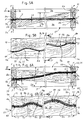
- Figs 1A and 1B generally present an example of the panel of the invention from the top and in perspective, seen nearly from two opposite directions and shown in unbroken lines. Further, Fig. 1B presents schematically, in lines of double dots and dashes, the next panel that steplessly fits the panel.
- Fig. 2 presents a frame consisting of two upper or lower parts of form bars and two upper or lower parts of support bars, to which the sheet material is glued according to the invention for producing the panel of Figs 1A and 1B, in axonometric view corresponding to the Fig. 1B.
- Fig. 3 shows the cutting or sawing in two of the form bar of the invention, as an upper and a lower part, in axonometric view, shown in unbroken lines.
- the figure also shows the cutting or sawing of the support bar in two, as an upper and a lower part, in lines of double dots and dashes.
- Fig. 4 shows the simultaneous cutting or sawing of two form bars of the invention in two as upper parts and lower parts so that the continuity of the surface shapes of the panels is made possible, in axonometric view.
- the figure also schematically shows the machine tool, with which the cutting/sawing is performed.
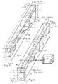
- Figs 5A and 5B show the glue pressing according to the invention for making one panel, in cross-sectional view corresponding to the plane II-II in Fig. 1A and 5B, and in side view corresponding to the direction I in Figs 1B and 5A.
- Figs 6A and 6B show the glue pressing according to the invention for simultaneously making two panels, in cross-sectional view corresponding to the plane IV-IV in Figs 1A and 6B, and in side view corresponding to the direction III in Figs 1B, 6A and 7.
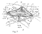
- Fig. 7 generally presents a second example of the panel of the invention from the top and in perspective, shown in unbroken lines, and further schematically the next panels that steplessly fit the panel in lateral and longitudinal direction and diagonally, shown in line of double dots and dashes.
- the panels 11, 12 of sheet material only comprise the upper parts 1b, 2b or lower parts 1a, 2a of form bars in the two opposite borders, to which the opposite borders 10 of the sheet material 7 are glued with the glue 9a.
- Figures 1 and 2 can also present such simple panels, especially the sturdiness of which is not the best possible, but which nevertheless are useful in some situations. However, also their surface shape has irregular protrusions and valleys.
- the method comprises following steps. First form bars 1; 2 are taken, the lengths Lm of which correspond to - i.e. are dimensioned so that they can be made to the size of the desired outer measures of the panels or to slightly smaller bearing parts - the lengths Lp or widths W of the panel sides and the heights of which are bigger than the maximum of the height difference Hp between the protrusions and valleys in the panel. Secondly, the form bars are cut longitudinally in two as upper parts 1b, 2b and lower parts 1a, 2a so that the cutting interface 5 is undulating in a desired way in the longitudinal direction of the bars and linear in the direction transverse to the length and height of the bars, as is shown in figures 3 and 4.
- the said cutting can be made using some slit machine tool, for example a band sawing machine or milling cutter or water jet or laser or some other respective known or new machine, which is able to cut the bar in two in the direction of its height Hm with as small and flat slit as possible.
- a cutting is the essential point of the invention, because with it two bar parts, i.e. an upper part and a lower part, are generated, which comprise the cutting surfaces 5a and 5b fitting exactly against each other and the cutting surfaces 6b and 6b, which will be described later.
- the lower parts 1a, 2a of the first and second form bar 1, 2 are placed at a distance corresponding to the width W or length Lp from each other, their cutting surfaces 5a upwards, and the first sheet material 7 is then arranged on these lower parts, with glue 9a between the cutting surfaces 5a and the lower surface 7a of the first sheet material against them.
- the cutting surface 5b of the upper part 1b of the first form bar is then putted against the upper surface 7b pointing away from the lower surface of the first sheet material at the region of the lower part 1a of the first form bar and in line with it, and the cutting surface 5b of the upper part 2b of the second form bar is pressed against the upper surface 7b pointing away from the lower surface of the first sheet material at the region of the lower part 2a of the second form bar and in line with it.
- the cutting surfaces of the two bar parts i.e. the upper part and the lower part fitting exactly against each other, described in the previous chapter, are here utilised, although in this simplest case the upper parts are only used in a way as a shaping tool.
- the upper parts 1b, 2b and the lower parts 1a, 2a are tightened against each other with such a force F that the borders 10 of the sheet material are set to follow the shapes of the cutting interface 5 between the lower parts and upper parts, and the glue 9a is let to harden.
- the first finished panel 11 can be detached from the said upper parts at the place of the interface marked with reference T, which is situated between the upper surface 7b of the first sheet material and the upper parts 1b, 2b of the form bars.
- a considerably sturdier panel is achieved by modifying the basic method of the invention described above to comprise the following additional steps and additional parts. Not even this method version has the best possible production efficiency, but as mentioned, the panel manufactured with this method already corresponds to the most advantageous embodiment of the invention.
- support bars 3; 4 are additionally taken, the lengths Lm of which correspond to - i.e. are dimensioned so that a frame of the size of the desired outer measures of the panel or a slightly smaller frame can be produced - the widths W or lengths Lp of the panel sides and the heights Hm of which are bigger than the maximum of the height difference Hp between the protrusions and valleys in the panel.
- These support bars are cut longitudinally in two as upper parts 3b, 4b and lower parts 3a, 4a so that the cutting interface 6 is substantially straight in the longitudinal direction of the bars and either parallel to the said length or inclined in the direction of the length, and linear in the direction transverse to the length and height of the bars.
- this cutting it is possible to produce two bar parts, i.e. the upper part and the lower part, which have cutting surfaces 6a and 6b fitting exactly against each other.
- first and second sheet material 7, 8 can generally bend only to some conic section so that undulating shape can only be found on two opposite borders 10 of the panel, and the other two borders 10 have to be straight, for example, extending in the direction of the lower surfaces 1c, 2c of the lower parts of the bars, or wedge-shaped in relation to these. If for example, in the case of Figs 1A and 2, the corners C1 and C2 or the corners C3 and C4 are examined, the undulating shape, i.e.
- the cutting surface 5a can first of all end to the same height from the lower surfaces 1c and 2c in both corners so that the cutting surface 6a of the lower parts 3a, 4a of the support bars has to be parallel to the lower surfaces 1c, 2c.
- the undulating shape i.e. the cutting surface 5a ends to a different height from the lower surfaces 1c and 2c in the opposite corners C1 and C2 or in the opposite corners C3 and C4
- the cutting surface 6a of the lower parts 3a, 4a of the support bars has to be inclined in relation to the lower surfaces 1c, 2c, i.e.
- the lower parts 3a, 4a of the support bars are wedge-shaped so that the cutting surfaces 6a of the lower parts of the support bars meet the cutting surfaces 5a of the lower parts 1a, 2a of the form bars at the corners.
- the first sheet material 7 can be attached to the lower parts along the whole length of all its borders 10, and in the alternative described later, the second sheet material 8 to the upper parts, respectively.
- the height of the lower parts and upper parts of the support bars has to be constant, such as half of the height Hm of the form bars, it is possible to alternatively take the otherwise finished upper parts 3b, 4b and lower parts 3a, 4a of the support bars, the lengths Lm of which correspond to the widths W or lengths Lp of the panel sides, and the heights Hm1/2 of which are half of the height of the form bars 1, 2.
- Such parts naturally contain the cutting surfaces 6a, 6b corresponding to the cutting interface 6 and extending in the direction of the length Lm.
- the lower parts 3a, 4a of the first and second support bar are placed at a distance of the panel's length Lp or, respectively, width W from each other and into connection with the lower parts 1a, 2a of the form bars, and the cutting surfaces 6a are placed, for example, upwards in the same direction as the cutting surfaces 5a of the lower parts of the form bars to form the frame 20 of the panel, which is shown in Figure 2.
- the lower parts of the form bars and support bars, and naturally also the upper parts, respectively can be attached, for example, to a mitre box preferably with glue, or with mechanical fastenings or forms that can be locked with each other, such as dovetail joints, to each other.
- the fastening is not always obligatory.
- the first sheet material 7 is arranged on the said lower parts, with glue 9a between the cutting surfaces 5a and 6a of all the lower parts 1a, 2a, 3a, 4a and the lower surface 7a of the sheet material against them.
- the cutting surface 5b of the upper part 1b of the form bar is then putted against the upper surface 7b of the first sheet material pointing away from the lower surface at the region of the lower part 1a of the first form bar and in line with it, and the cutting surface 5b of the upper part 2b of the second form bar is pressed against the upper surface 7b of the first sheet material at the region of the lower part 2a of the second form bar and in line with it, and secondly, the cutting surface 6b of the upper part 3b of the first support bar is pressed against the upper surface 7b of the first sheet material at the region of the lower part 3a of the first support bar and in line with it, and the cutting surface 6b of the upper part 4b of the second support bar is pressed against the upper surface 7b of the first sheet material at the region of the lower part 4a of the second support bar and in line with it, or respectively.
- the first of the advantageous embodiments of the panel of sheet material according to the invention has thus been achieved, which comprises: the lower parts 1a and 2a or upper parts 1b and 2b at a distance of the panel's width W or length Lp from each other, the cutting surfaces 5a, 5b of which are undulating in the longitudinal direction of the bars and linear in the direction transverse to the length and height of the bars; lower parts 3a and 4a or upper parts 3b and 4b of the support bars at a distance of the panel's length Lp or respectively width W from each other, with straight cutting surfaces 6a, 6b; in the said cutting surfaces 5a and 6a; or 5b and 6b pointing to the same direction the sheet material 7 or 8 fastened from its borders 10 with glue 9a or 9b, the borders 10 following the forms of the cutting surfaces 5a and 6a; or 5b and 6b; and the sheet material 7 or 8 stays in its entirety in stress state.
- the most advantageous embodiment of the method of the invention contains additional phases, which however reduce the working steps to be made in all and make the manufacture considerably faster when manufacturing several panels according to the invention.
- the second sheet material 8 is placed onto the first sheet material 7 on the said lower parts 1a, 2a, 3a, 4a so that its lower surface 8a is against the upper surface 7b of the first sheet material.
- absolutely no glue is applied between the first sheet material 7 and the second sheet material 8.
- the cutting surface 5b of the upper surface 1b of the first form bar is placed against the upper surface 8b of the second sheet material at the region of the lower part 1a of the first shaped bar and in line with it, and the cutting surface 5b of the upper part 2b of the second form bar against the upper surface 8b of the second sheet material at the region of the lower part 2a of the second form bar and in line with it, and further, the cutting surface 6b of the upper surface 3b of the first support bar is placed against the upper surface 8b of the second sheet material at the region of the lower part 3a of the first support bar and in line with it, and the cutting surface 6b of the upper part 4b of the second support bar against the upper surface 8b of the second sheet material at the region of the lower part 4a of the second support bar and in line with it, or respectively.
- the upper parts 3b, 4b of the first and second support bar at a distance of the panel's length Lp or, respectively, width W away from each other and into connection with the upper parts 1b, 2b of the form bars, and the cutting surfaces 6b to the same direction as the cutting surfaces 5b of the upper parts of the form bars to form the panel frame 20, which is shown in Figure 2.
- the upper parts are thus preferably placed as a complete frame 20, the cutting surfaces 5b, 6b downwards, against the upper surface 8b of the second sheet material, as is shown in Figures 6A and 6B, with glue 9b between the cutting surfaces 5b, 6b of the upper parts and the upper surface 8b of the second sheet material against them.
- the said upper parts 1b, 2b, 3b, 4b, and the lower parts 1a, 2a, 3a, 4a are tightened towards each other with such a force F that the borders 10 of the sheet material set to follow the forms of the cutting interfaces 5, 6 between the lower parts and the upper parts.
- both the glues 9a, 9b are let to harden, and the first and second panel 11, 12 are then detached from each other along the interface T between the first sheet material 7 and the second sheet material 8.
- the detachment is simply performed by only lifting these two finished panels 11 and 12 away, because they have not been attached to each other in any way, but they are superimposed and aligned with each other only for tightening with the force F and for pressing the borders 10 of the first sheet material 7 accurately against the cutting surfaces 5a, 6b of the upper surfaces of the bars.
- the glues 9a, 9b between these cutting surfaces 5a, 6a and the borders of the first sheet material 7 and, respectively, the cutting surfaces 5b, 6b and the borders of the second sheet material 8 keep the borders of the sheet materials attached to the undulating and straight cutting surfaces of the lower parts 1a, 2a, 3a, 4a and the upper parts 1b, 2b, 3b, 4b, respectively, after the panels have been detached from each other.
- the undulating shape of the cutting interface 5 between the upper parts 1b, 2b and the lower parts 1a, 2a of the form bars in the longitudinal direction of the bars has been arranged so that several upper parts 1b, 2b and a lower part 1a, 2a of different undulating shapes are available for assembling the panels.
- at least five different undulating shapes are used so that 24 different panels are produced, but typically at least seven different undulating shapes so that 720 different panels are produced, and preferably at least ten different undulating shapes so that 362880 different panels are produced.
- the undulating shape 5 is changing in series.
- the undulating shape of the cutting interface 5 between the upper parts 1b, 2b and the lower parts 1a, 2a of the form bars can be arranged to be individual in each form bar, which can easily be done by using a computer not shown in the figures with a suitable program for controlling the slit machine tool.
- a suitable computer program it is possible to form practically almost an infinite number of different undulating shapes to the cutting interface 5.
- the first and second sheet material 7, 8 are prefabricated, substantially straight boards, for example, of suitable commercially available plywood, which have two or several layers of veneer glued permanently together beforehand.
- the sheet materials 7, 8 can alternatively also be prefabricated, substantially straight metal plates or plastic boards or fabric sheets pre-stiffened with a suitable polymer or organic substance, such as starch, or felt sheets, or some other corresponding board material.
- the sheet material boards being substantially straight refers to that they have not been shaped in advance in the direction of their thickness S.
- the sheet material boards have to be substantially rigid so that they retain their form when fastened between the form bars and the possible support bars, but however flexible to the extent that their borders shape to contact the form bars and the possible support bars without excessive use of force and that the applied gluing holds them fast to the form bars and support bars.
- the sheet material boards when lowered to a planar base, also have to adopt a nearly planar position and, for example, comprising 1 m 2 and being supported only from its two opposite borders, bend under their own weight, but only slightly, for example 3mm ... 15 cm.
- a sheet material board has a suitable flexibility and rigidity as the product E ⁇ I of its Young's modulus of elasticity and the stiffness moment is approximately 0.5 N ⁇ m 2 -50 N ⁇ m 2 , as the stiffness moment of the flat material is b ⁇ h 3 /12, as is well known.
- the thickness S of the first and second sheet material 7, 8 is under 1 mm, but preferably the thickness of the first and second sheet material 7, 8 is between 0.3 mm - 0.7 mm so that the panels can be made permeable to light, at least to some extent.
- the thickness S of the first and second sheet material 7, 8 is under 0.5 mm, but preferably the thickness of the first and second sheet material 7,8 is 0.1 mm - 0.3 mm.
- the thickness S of the sheet materials 7, 8 can vary within very extensive limits, from 5 mm to 0.3 mm, depending on the properties of the impregnating medium. It is generally preferable to use a rather small amount of the stiffening impregnating medium so that the fabric, or especially the felt, stays porous.
- sheet material boards manufactured by pre-laminating of the said materials can be used, in which case its thickness corresponds to that defined above, where applicable.
- the sheet material boards can also be pre-perforated in a suitable way for reasons of appearance or for improving the acoustic properties.
- the material for the form bars 1, 2 and the possible support bars 3, 4 can be massive wood, plywood, laminated veneer lumber or plastic or possibly metal, or a combination these.
- the glues 9a, 9b are applied either to the surfaces of the borders 10 of the sheet materials 7,8 at the place of the cutting surfaces 5a, 5b, 6a, 6b of the lower parts or upper parts of the bars coming against them, or alternatively, to the cutting surfaces 5a, 5b, 6a, 6b of the lower parts or upper parts of the bars, or to both. It can also be done so that the actual glue is applied to the ones of these and the hardening agent of the glue to the other ones so that the time of treatment for the parts is longer, as the hardening can only begin after the borders of the sheet materials 7, 8 and the cutting surfaces 5a, 5b, 6a, 6b of the bars come into contact with each other. Any glue suitable for the purpose can be used as the glue.
- the said tightening of the upper parts 1b, 2b, 3b, 4b and the lower parts 1a, 2a, 3a, 4a against each other with the force F for making the borders 10 of the sheet materials to follow the forms of the cutting surfaces 5, 6 is preferably performed in room temperature.
- room temperature no heating is normally used in the invention for shaping the sheet materials, and heat is actually not needed, because the finished sheet materials 7, 8 used according to the invention - unlike for example separate wood veneers - are hardly shaped by the influence of heat.
- the temperature has to be sufficiently high and the environmental circumstances have to be such that the glues 9a, 9b harden in the appropriate way. Nevertheless, nothing prevents the use of elevated temperature to make the glues 9a and 9b to harden faster.
- the one side of one panel has the similar undulating shape as the one side of a second panel so that the protrusions and valleys of the outwards facing sheet materials 7, 8 of the panels progress in a continuous manner from one panel to the other
- the form bars are then cut longitudinally in two as upper parts 1b, 2b and lower parts 1a, 2a along the said undulating cutting interface 5, two form bars 1 and 101, or 2 and 102, at a time - in the case described previously, one form bar 1 or 2 at a time, as is shown in Figure 3 - placed side by side, as is shown in Figure 4.
- the upper parts 1b, 2b and lower parts 1a, 2a which are identical with each other, are then used in the same position to manufacture different panels by placing them to the opposite sides of the different panels.
- the side surfaces 17 and 18 of the form bars 1 and 101 and 2 and 102, respectively, facing each other or against each other, are arranged as outwards pointing side surfaces in the panels.
- the backwards pointing side surface of the front panel 11, 12 out of sight is the first side surface 17 - visible in Fig. 1A - and the forwards pointing side surface of the back panel 13, 14, 15, 16, which is out of sight behind the foremost panel, is the second side surface 18.
- the first panel 11 comprises the lower parts 1a and 2a of the first and second form bars 1 and 2, which thus are different, the first side surface 17 outwards
- the third panel 13 comprises at least the lower part 1a of the third form bar 101 the second side surface 18 outwards.
- the second panel 12 comprises the upper parts 1b and 2b of the first and second form bar 1 and 2, which thus are different, the first side surface 17 outwards
- the fourth panel 14 comprises at least the upper part 1b of the third form bar 101 the second side surface 18 outwards.
- the first panel 11 comprises the lower parts 1a and 2a of the first and second form bar 1 and 2, which thus are different, the first side surface 17outwards
- the fifth panel 15 comprises at least the lower part 2a of the fourth form bar 102 the second side surface 18 outwards.
- the second panel 12 comprises the upper parts 1b and 2b of the first and second form bar 1 and 2, which thus are different, the first side surface 17 outwards
- the sixth panel 16 comprises at least the upper part 2b of the fourth form bar 102 the second side surface 18 outwards.
- Two panels are then mounted for use one after the other: the first and third panel 11 and 13 so that the lower parts of the first and, respectively, the third form bar are side by side, the second and the fourth panel 12 and 14 so that the upper parts of the first and, respectively, the third form bar are side by side, the first and the fifth panel 11 and 15 so that the lower parts of the first and, respectively, the fourth form bar are side by side, the second and the sixth panel 12 and 16 so that the upper parts of the first and, respectively, the fourth form bar are side by side.
- the surface shape containing irregular protrusions and valleys continues substantially unbroken from panel to panel, with the exception of the possible smaller or larger slit between the panels.
- the panels can also be placed so that they are attached to each other.
- An alternative embodiment of the method is to manufacture and use additional form bars instead of the support bars.
- additional form bars 1; 2 are taken, the lengths Lm of which correspond to the widths W or lengths Lp of the panel sides and the heights Hm of which are larger than the maximum of the height difference Hp between the protrusions and valleys in the panel.
- these form bars are cut longitudinally in two as upper parts 1e, 2e and lower parts 1d, 2d so that the cutting interface 5 is undulating in the longitudinal direction of the bars and linear in the direction transverse to the length and height of the bars.
- these upper parts 1d, 2d of the first and second additional form bar are placed at a distance of the panel length Lp or, respectively, the width W away from each other and into connection with the previously described lower parts 1a, 2a of the form bars and the cutting surfaces 6a, 6b upwards, to form the frame 20 of the panel.
- These lower and upper parts of the additional form bars are thus used the same way as the lower and upper parts of the support bars, but the parts of the additional form bars have undulating surfaces unlike the parts of the support bars.
- the first sheet material 7 is arranged onto the said lower parts, with glue 9a between the cutting surfaces 5a and 6a of all the lower parts 1a, 2a, 1d, 2d and the lower surface 7a of the sheet material against them.
- the cutting surfaces 5b of the upper parts 1e of the first form bars are then pressed against the upper surface 7b pointing away from the lower surface of the first sheet material at the region of the lower parts 1d of the first form bars and in line with them, and the cutting surfaces 5b of the upper parts 2e of the second form bars are putted against the upper surface 7b of the first sheet material at the region of the lower parts 2d of the second form bars and in line with them, or respectively, and the said upper parts 1b, 2b, 1e, 2e and the lower parts 1a, 2a, 1d, 2d are tightened towards each other with such a force F that the borders 10 of the sheet material are set to follow the forms of the cutting interfaces 5, 6 between the lower parts and the upper parts.
- the glue 9a is let to harden, and the first panel 11 is detached from the said upper parts.
- the result is a panel according to Figure 7, in which all the sides are undulating.
- the undulating shapes of all the sides in the panel in Figure 7 can be identical so that the protrusions and valleys of parallel panels are repeated in the two general directions of the surface perpendicular to each other.
- the undulating shapes of all the sides can also be different so that the protrusions and valleys of parallel panels change continuously in the two general directions perpendicular to each other.
- the second advantageous embodiment of the panel of sheet material of the invention which thus comprises the lower parts 1a and 2a or the upper parts 1b and 2b of the form bars that are at a distance of the panel's width W or length Lp away from each other, the parts having cutting surfaces 5a, 5b undulating in the longitudinal direction of the bars and linear in the direction transverse to the length and height of the bars, and with the first and second end height H1, H2, and the lower parts 1d and 2d or the upper parts 1e and 2e of the form bars that are at a distance of the panel's Lp or width W away from each other, the form bars having cutting surfaces 5a, 5b undulating in the longitudinal direction of the bars and linear in the direction transverse to the length and height of the bars, and with also a second and a first end height H1, H2.
- the sheet material 7 or 8 is attached from its borders 10 in the cutting surfaces 5a and 5b pointing to the same direction with glue 9a or 9b, the borders 10 thus following the forms of the cutting surfaces 5a and 5b, while the sheet material 7 or 8 remains in its entirety in stress state.
- the ends of the lower parts 1a, 2a, 1d, 2d and of the upper parts 1b, 2b, 1e, 2e, respectively, are dimensioned to have either the first end height H1 or the second end height H2, and two such bar parts with the same end height, either H1 or H2, is fitted to connect to each other in each corner of the panel.
- the first end height H1 is typically different from the second end height H2 so that most simply, but not necessarily, the bar parts of all sides of the panel can be identical, or the first end height H1 can be of the same size as the second end height H2, in which case at least the opposite sides of the panels have to have bar parts 1a, 2a, 1d, d; 1b, 2b, 1e, 2e with different cutting surfaces.
- the bar parts 1a, 2a, 1d, d; 1b, 2b, 1e, 2e with different cutting surfaces.
- the average height H of the lower parts 1a and 2a; 1d and 2d or the upper parts 1b and 2b; 1e and 2e of the form bars and the lower parts 3a and 4a or the upper parts 3b and 4b of the possible support bars is dimensioned to provide the sheet material 7, 8 with a distance from the planned fastening point, typically from the lower surfaces 1c and 2c and respective parts, suitable for each acoustic purpose.
Landscapes
- Engineering & Computer Science (AREA)
- Architecture (AREA)
- Life Sciences & Earth Sciences (AREA)
- Wood Science & Technology (AREA)
- Civil Engineering (AREA)
- Structural Engineering (AREA)
- Manufacturing & Machinery (AREA)
- Mechanical Engineering (AREA)
- Forests & Forestry (AREA)
Applications Claiming Priority (2)
| Application Number | Priority Date | Filing Date | Title |
|---|---|---|---|
| FI20011537A FI111822B (fi) | 2001-07-13 | 2001-07-13 | Vanerinen paneeli |
| FI20011537 | 2001-07-13 |
Publications (1)
| Publication Number | Publication Date |
|---|---|
| EP1275480A2 true EP1275480A2 (en) | 2003-01-15 |
Family
ID=8561654
Family Applications (1)
| Application Number | Title | Priority Date | Filing Date |
|---|---|---|---|
| EP20020396113 Withdrawn EP1275480A2 (en) | 2001-07-13 | 2002-07-03 | Panel of sheet material |
Country Status (2)
| Country | Link |
|---|---|
| EP (1) | EP1275480A2 (fi) |
| FI (1) | FI111822B (fi) |
Cited By (8)
| Publication number | Priority date | Publication date | Assignee | Title |
|---|---|---|---|---|
| EP1582652A2 (de) | 2004-02-04 | 2005-10-05 | Kamal Dr. Mostafa | Mosaikartiger Bauflächenbelag mit höhenmodellierbarer Oberfläche |
| WO2006011004A1 (en) * | 2004-07-19 | 2006-02-02 | Erdweg, Jan | Floor covering having two distinct representations |
| GB2431941A (en) * | 2005-11-04 | 2007-05-09 | Gram Engineering Pty Ltd | Steel panel which simulates a natural material through surface undulations |
| EP2202365A3 (de) * | 2009-02-05 | 2011-07-27 | NATCON Nature Construction Sima GmbH & Co. KG | Verfahren zum Herstellen eines Bauwerks und damit hergestelltes Bauwerk |
| CN105324201A (zh) * | 2013-06-19 | 2016-02-10 | 梅卡奇罗梅法国公司 | 切割金属或复合材料制料坯块而获得的板材或工件套件 |
| US20190203477A1 (en) * | 2018-01-03 | 2019-07-04 | Boral Ip Holdings (Australia) Pty Limited | Panel for attachment to a mounting surface of a building structure and method of making the same |
| EP3010689B1 (fr) * | 2013-06-19 | 2019-07-17 | Mecachrome France | Dispositif et procédé de découpe de pièces en matériau metallique ou composite |
| USD919126S1 (en) | 2018-01-03 | 2021-05-11 | Boral Ip Holdings (Australia) Pty Limited | Panel |
-
2001
- 2001-07-13 FI FI20011537A patent/FI111822B/fi not_active IP Right Cessation
-
2002
- 2002-07-03 EP EP20020396113 patent/EP1275480A2/en not_active Withdrawn
Cited By (13)
| Publication number | Priority date | Publication date | Assignee | Title |
|---|---|---|---|---|
| EP1582652A2 (de) | 2004-02-04 | 2005-10-05 | Kamal Dr. Mostafa | Mosaikartiger Bauflächenbelag mit höhenmodellierbarer Oberfläche |
| EP1582652A3 (de) * | 2004-02-04 | 2007-08-15 | Kamal Dr. Mostafa | Mosaikartiger Bauflächenbelag mit höhenmodellierbarer Oberfläche |
| WO2006011004A1 (en) * | 2004-07-19 | 2006-02-02 | Erdweg, Jan | Floor covering having two distinct representations |
| GB2431941A (en) * | 2005-11-04 | 2007-05-09 | Gram Engineering Pty Ltd | Steel panel which simulates a natural material through surface undulations |
| EP2202365A3 (de) * | 2009-02-05 | 2011-07-27 | NATCON Nature Construction Sima GmbH & Co. KG | Verfahren zum Herstellen eines Bauwerks und damit hergestelltes Bauwerk |
| JP2016522096A (ja) * | 2013-06-19 | 2016-07-28 | メカクローム・フランスMecachrome France | 金属または複合材料のブロックの切削により得られる板または部品の組 |
| CN105324201A (zh) * | 2013-06-19 | 2016-02-10 | 梅卡奇罗梅法国公司 | 切割金属或复合材料制料坯块而获得的板材或工件套件 |
| EP3010689B1 (fr) * | 2013-06-19 | 2019-07-17 | Mecachrome France | Dispositif et procédé de découpe de pièces en matériau metallique ou composite |
| EP3010675B1 (fr) * | 2013-06-19 | 2020-08-19 | Mecachrome France | Ensemble de plaques obtenues par decoupe d'un bloc en materiau metallique ou composite |
| US20190203477A1 (en) * | 2018-01-03 | 2019-07-04 | Boral Ip Holdings (Australia) Pty Limited | Panel for attachment to a mounting surface of a building structure and method of making the same |
| US10378213B2 (en) * | 2018-01-03 | 2019-08-13 | Boral Ip Holdings (Australia) Pty Limited | Panel for attachment to a mounting surface of a building structure and method of making the same |
| USD919126S1 (en) | 2018-01-03 | 2021-05-11 | Boral Ip Holdings (Australia) Pty Limited | Panel |
| US11512478B2 (en) | 2018-01-03 | 2022-11-29 | Westlake Royal Building Products Inc. | Panel for attachment to a mounting surface of a building structure and method of making the same |
Also Published As
| Publication number | Publication date |
|---|---|
| FI111822B (fi) | 2003-09-30 |
| FI20011537A (fi) | 2003-01-14 |
| FI20011537A0 (fi) | 2001-07-13 |
Similar Documents
| Publication | Publication Date | Title |
|---|---|---|
| EP1275480A2 (en) | Panel of sheet material | |
| CA2581103C (en) | Lightweight structural panel and method for making same | |
| EP1714776A1 (en) | Three dimensional core, board material, block of material and methods for making these | |
| EP1336471B1 (en) | Method for manufacturing curved furnishing components, particularly door panels for furniture, and article obtainable with the method | |
| US5832692A (en) | Panel construction and method for manufacturing | |
| DK172290B1 (da) | Fremgangsmåde til fremstilling af en krum træfiberplade, møbelplade til brug ved udøvelse af fremgangsmåden og træfiberplade fremstillet ved fremgangsmåden. | |
| CA2509623A1 (en) | Diagonal laminated veneer lumber and method of manufacturing the same | |
| EP1634514B1 (de) | Verfahren und Vorrichtung zur Herstellung von Möbelplatten | |
| WO1990004515A1 (en) | Method of manufacturing structural elements, especially furniture components | |
| US4963212A (en) | Method for making a composite body | |
| FI86388B (fi) | Foerfarande foer framstaellning av en flerskiktstraeskiva. | |
| JPS61213102A (ja) | 単板積層板の製造方法 | |
| JP3134649B2 (ja) | ハニカムパネル及びハニカムパネル製造法 | |
| CN220280770U (zh) | 一种抗弯复合板 | |
| CN218206414U (zh) | 一种新型岩板门板 | |
| KR0169448B1 (ko) | 목재 상감 무늬목 제조방법 | |
| CN2878582Y (zh) | 一种复合地板 | |
| JP3719598B2 (ja) | 卓球台用天板 | |
| AU2005100349A4 (en) | Furniture Part and Process for Making Same | |
| JPH0411069Y2 (fi) | ||
| EP1162050A1 (en) | Method for manufacturing an insulating element, and insulating element so obtained | |
| EP0767033A1 (en) | Method for forming framed panels clad with sheets of thermodeformable material and panel obtained by the method | |
| CN2284144Y (zh) | 竹材层积薄竹刨切单板 | |
| EP2452792A1 (en) | Panel and method for manufacturing panels | |
| RU2030196C1 (ru) | Способ изготовления монолыжи |
Legal Events
| Date | Code | Title | Description |
|---|---|---|---|
| PUAI | Public reference made under article 153(3) epc to a published international application that has entered the european phase |
Free format text: ORIGINAL CODE: 0009012 |
|
| AK | Designated contracting states |
Kind code of ref document: A2 Designated state(s): AT BE BG CH CY CZ DE DK EE ES FI FR GB GR IE IT LI LU MC NL PT SE SK TR |
|
| AX | Request for extension of the european patent |
Free format text: AL;LT;LV;MK;RO;SI |
|
| STAA | Information on the status of an ep patent application or granted ep patent |
Free format text: STATUS: THE APPLICATION HAS BEEN WITHDRAWN |
|
| 18W | Application withdrawn |
Effective date: 20040708 |
|
| R18W | Application withdrawn (corrected) |
Effective date: 20040709 |