EP1275287A1 - Schneidwerk für Erntemaschinen - Google Patents
Schneidwerk für Erntemaschinen Download PDFInfo
- Publication number
- EP1275287A1 EP1275287A1 EP02014747A EP02014747A EP1275287A1 EP 1275287 A1 EP1275287 A1 EP 1275287A1 EP 02014747 A EP02014747 A EP 02014747A EP 02014747 A EP02014747 A EP 02014747A EP 1275287 A1 EP1275287 A1 EP 1275287A1
- Authority
- EP
- European Patent Office
- Prior art keywords
- skids
- cutting
- cutting unit
- upper position
- cutting mechanism
- Prior art date
- Legal status (The legal status is an assumption and is not a legal conclusion. Google has not performed a legal analysis and makes no representation as to the accuracy of the status listed.)
- Granted
Links
- 238000003306 harvesting Methods 0.000 title claims abstract description 19
- 235000010469 Glycine max Nutrition 0.000 claims abstract 3
- 244000068988 Glycine max Species 0.000 claims abstract 3
- 239000000463 material Substances 0.000 claims description 6
- 239000000725 suspension Substances 0.000 claims description 6
- 241001124569 Lycaenidae Species 0.000 claims description 5
- 230000002787 reinforcement Effects 0.000 claims description 4
- 235000013399 edible fruits Nutrition 0.000 claims description 3
- 235000013339 cereals Nutrition 0.000 abstract 1
- 235000010627 Phaseolus vulgaris Nutrition 0.000 description 8
- 244000046052 Phaseolus vulgaris Species 0.000 description 8
- 239000002689 soil Substances 0.000 description 8
- 238000006243 chemical reaction Methods 0.000 description 2
- 230000001464 adherent effect Effects 0.000 description 1
- 239000000969 carrier Substances 0.000 description 1
- 238000003780 insertion Methods 0.000 description 1
- 230000037431 insertion Effects 0.000 description 1
- 238000012423 maintenance Methods 0.000 description 1
- 238000004519 manufacturing process Methods 0.000 description 1
- 125000006850 spacer group Chemical group 0.000 description 1
- 230000000087 stabilizing effect Effects 0.000 description 1
Images

Classifications
-
- A—HUMAN NECESSITIES
- A01—AGRICULTURE; FORESTRY; ANIMAL HUSBANDRY; HUNTING; TRAPPING; FISHING
- A01D—HARVESTING; MOWING
- A01D41/00—Combines, i.e. harvesters or mowers combined with threshing devices
- A01D41/12—Details of combines
- A01D41/14—Mowing tables
Definitions
- the invention relates to a cutting unit for harvesters, especially for self-propelled Combines, both for the harvest of grain and crops with low lying fruit stalls, according to the preamble of claim 1.
- the invention has for its object to run the skids and arrange, that a trouble-free operation is guaranteed under all harvesting conditions, and that the change of equipment variants in a simple way with a low workload can be carried out.
- skids and their locking device according to the invention in the upper position becomes a universal with a low production cost Possible application for different crops achieved.
- plastic skids aresfedernd trained, so that a fault-prone mechanical Joint connection with the cutting trough is not required.
- the non-adherent Surface allows especially in wet and sticky soil conditions much better gliding over the field soil.
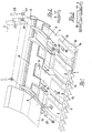
- a cutting unit For cutting the crop is at the front of a not shown in the drawing Combine arranged a cutting unit. It essentially comprises a cutting trough 1, a feed screw conveyor 2, a flexible cutter bar 3 with mower blade and a plurality of juxtaposed skids 4.
- a cutting trough 1 In the lower rear of the Cutting trough 1 is arranged over the entire width of a continuous support tube 5, at the intervals approximately horizontally extending profiled bottom support 6 and the rear wall 7 are attached.
- Between each two adjacent floor beams 6 are transverse Connection plates 8 and profile support 9 for stabilizing the cutting trough 1 arranged.
- a bottom plate 10 Above the connecting plates 8 and profile carrier 9, a bottom plate 10 is attached, which extends over the entire width of the cutting trough 1 and from individual Sections exists.
- skids 4 Made of a self-springing and smooth-surfaced plastic with good Slip properties existing skids 4 are at their rear ends over Screw 11 directly to the connection plates 8 or other bottom side Frame parts of the cutting trough 1 rigidly attached. Also via screw connections 12, the front ends of the skids 4 are connected to the cutter bar 3. At the Cutter bar 3 are in a known manner, the mowing fingers 13 and a mower blade, not shown arranged. In the front area, the skids 4 a directed to the field bottom Buckle 14, which essentially establishes the ground contact. Since this vault 14 a subject to high stress, it is on the bottom side with an additional interchangeable Edition 15 provided. As a result, in the event of wear, this area can easy replacement of the pad 15 to restore full functionality.
- the cutting unit according to the invention is suitable for both the harvest of grain as well as beans or other crops with low lying Fruit stands suitable.
- the cutting unit While at the grain harvest, the cutting unit at a distance is guided over the field soil and the mower blade in a straight line the stalks When cutting beans, the cutting unit is lowered so far that the skids 4 have contact with the ground over the entire cutting width and the flexible cutter bar 3 with the mower blade transversely to the direction of elastic spring constantly changing soil profile adapts and in all areas of the mowing blade an optimal low Cutting height is achieved.
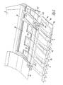
- the vertical movement possibility of the skids 4 is canceled, by being brought to bear on the underside of the profile carrier 9 and in this position be arrested.
- the locking of the skids 4 takes place in two different variants.
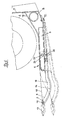
- the skids 4 by means of a Seilzug worn brought into the upper position. This is to each one in the lateral Arranged end portions of the cutting unit and a bottom support 6 associated skid 4 attached to a bolt 19 and a pull cable 20, which via pulleys 21 to a arranged on the rear wall 7 rotary drive 22 or traction drive 23 leads.
- Fig. 1 is the Rotary drive 22 with full lines and the traction drive 23 shown with dash-dot lines. Both electrically or hydraulically actuated drives are from the driver's station of the harvester from served. By the cable drive the skids 4 to stop lifted the profile carrier 9 and held in this position.
- a relief of the skids 4 receiving To reach the cutting unit and the carrier vehicle is that of the skids 4 on adjustable ground pressure p adjustable.
- this can be done by changing the mounting angle ⁇ below the respective skid 4 connected in its rear region with the frame part 8 of the cutting trough 1 is done. It is within the scope of the invention that this change of the mounting bracket ⁇ by changing the inclination angle of the rear end of the skid 4 or by Insertion of wedge-shaped spacers in the area of the screw 11 between the frame part 8 of the cutting trough 1 and the respective skid 4 is feasible.
- the change of the contact pressure p one or more skids 4 also be achieved in that skids. 4 used with different material thickness and / or different material properties become.
Landscapes
- Life Sciences & Earth Sciences (AREA)
- Environmental Sciences (AREA)
- Harvesting Machines For Specific Crops (AREA)
- Harvester Elements (AREA)
- Harvesting Machines For Root Crops (AREA)
Abstract
Description
- Fig. 1
- eine perspektivische Ansicht auf den unteren Bereich eines Schneidwerkes mit Gleitkufen, die über eine Seilzugeinrichtung in die obere Stellung gebracht und dort gehalten werden,
- Fig.2
- den Schnitt II-II nach Fig.1,
- Fig.3
- den Schnitt III-III nach Fig.1,
- Fig.4
- einen Querschnitt durch den unteren Bereich eines Schneidwerkes mit Gleitkufen , die nach Fig. mittels einer Seilzugeinrichtung in die obere Stellung gebracht werden,
- Fig.5
- eine perspektivische Ansicht auf den unteren Bereich eines Schneidwerkes mit Gleitkufen, die mit Schwenkhaken in der oberen Stellung gehalten werden,
- Fig.6
- einen Querschnitt durch den unteren Bereich eines Schneidwerkes mit Gleitkufen, die nach Fig.5 mit Schwenkhebeln in der oberen Stellung gehalten werden.
- 1.
- Schneidwerksmulde
- 2.
- Einzugsförderschnecke
- 3.
- Mähbalken
- 4.
- Gleitkufen
- 5.
- Tragrohr
- 6.
- Bodenträger
- 7.
- Rückwand
- 8.
- Verbindungsplatten
- 9.
- Profilträger
- 10.
- Bodenblech
- 11.
- Schraubverbindungen
- 12.
- Schraubverbindungen
- 13.
- Mähfinger
- 14.
- Wölbung
- 15.
- Auflage
- 16.
- Verstärkung
- 17.
- Einlagen
- 18.
- Platten
- 19.
- Bolzen
- 20.
- Zugseil
- 21.
- Umlenkrollen
- 22.
- Drehantrieb
- 23.
- Zugantrieb
- 24.
- Schwenkhaken
- 25.
- Welle
- 26.
- Einhängebolzen
- 27.
- Handhebel
Claims (13)
- Schneidwerk für Erntemaschinen, insbesondere für selbstfahrende Mähdrescher, sowohl für die Ernte von Getreide als auch von Erntegut mit niedrig liegenden Fruchtständen, beispielsweise von Sojabohnen, mit einem Mähbalken, der über mehrere nebeneinander in Fahrtrichtung verlaufende Gleitkufen wahlweise starr oder gelenkig mit der Schneidwerksmulde verbunden ist und die Gleitkufen zwischen einer unteren und oberen Stellung in vertikaler Richtung bewegbar sind oder in der oberen Stellung über eine im vorderen Bereich angeordnete Arretiervorrichtung feststellbar sind,
dadurch gekennzeichnet, dass, die Gleitkufen (4) an ihren rückwärtigen Enden über starre Schraubverbindungen (11) unmittelbar an Rahmenteilen (8) der Schneidwerksmulde (1) befestigt sind und dass die Gleitkufen (4) über eine Seilzugeinrichtung (19-23) in die obere Stellung anhebbar und arretierbar sind und/oder dass die Gleitkufen (4) über zumindest einen Schwenkhaken (24) und wenigstens einen mitwirkenden Einhängebolzen ( 26) in der oberen Stellung arretierbar sind. - Schneidwerk nach Anspruch 1
dadurch gekennzeichnet, dass die Seilzugeinrichtung (19-23) vom Fahrerstand der Erntemaschine aus bedienbar und elektrisch oder hydraulisch antreibbar ist. - Schneidwerk nach einem oder mehreren der vorhergehenden Ansprüche,
dadurch gekennzeichnet, dass an jedem Seitenbereich des Schneidwerkes eine Seilzugeinrichtung angeordnet ist, wobei an zumindest einer, einem Bodenträger (6) zugeordneten Gleitkufe (4) an einem Bolzen (19) ein Zugseil (20) befestigt ist, das über Umlenkrollen (21) zu einem an der Rückwand (7) des Scheidwerkes angeordneten Drehantrieb (22) oder Zugantrieb (23) führt. - Schneidwerk nach einem oder mehreren der vorhergehenden Ansprüche,
dadurch gekennzeichnet, dass der wenigstens ein Schwenkhaken (24) auf einer innerhalb der Profilträger (9) verlaufenden durchgehenden Welle (25) im Bereich eines Bodenträgers (6) und der wenigstens eine mitwirkende Einhängebolzen (26) in einer unmittelbar darunter liegenden Gleitkufe (4) befestigt ist und dass am äußeren Ende der Welle (25) ein Handhebel (27) angeordnet ist. - Schneidwerk nach Anspruch 4,
dadurch gekennzeichnet, dass der durchgehenden Welle (25) eine Vielzahl von Schwenkhaken (24) und mit diesen Schwenkhaken (24) zusammenwirkende Einhängebolzen (26) zugeordnet sind. - Schneidwerk Schneidwerk für Erntemaschinen, insbesondere für selbstfahrende Mähdrescher, sowohl für die Ernte von Getreide als auch von Erntegut mit niedrig liegenden Fruchtständen, beispielsweise von Sojabohnen, mit einem Mähbalken, der über mehrere nebeneinander in Fahrtrichtung verlaufende Gleitkufen wahlweise starr oder gelenkig mit der Schneidwerksmulde verbunden ist und die Gleitkufen zwischen einer unteren und oberen Stellung in vertikaler Richtung bewegbar sind oder in der oberen Stellung über eine im vorderen Bereich angeordnete Arretiervorrichtung feststellbar sind,
dadurch gekennzeichnet,
das der Auflagedruck (p) wenigstens einer Gleitkufe (4) einstellbar ist. - Schneidwerk nach Anspruch 6,
dadurch gekennzeichnet, dass die Einstellbarkeit des Auflagedrucks (p) durch Änderung des Montagewinkels (α) der wenigstens einen Gleitkufe (4) an dem Rahmenteil (8) der Schneidwerksmulde (1) erfolgt. - Schneidwerk nach einem oder mehreren der Ansprüche 6 und 7,
dadurch gekennzeichnet, dass die Einstellbarkeit des Auflagedrucks (p) durch den Einsatz von Gleitkufen (4) mit unterschiedlicher Materialstärke und/oder verschiedenen Materialeigenschaften erreicht wird. - Schneidwerk nach einem oder mehreren der vorhergehenden Ansprüche,
dadurch gekennzeichnet, dass die Gleitkufen (4) aus einem selbstfederndem und glattflächigem Kunststoff bestehen. - Schneidwerk nach einem oder mehreren der vorhergehenden Ansprüche,
dadurch gekennzeichnet, dass die Gleitkufen (4) im vorderen Bereich eine zum Feldboden gerichtete Wölbung (14) aufweisen. - Schneidwerk nach Anspruch 10
dadurch gekennzeichnet, dass die Wölbung (14) bodenseitig mit einer auswechselbaren Auflage (15) versehen ist. - Schneidwerk nach einem oder mehreren der vorhergehenden Ansprüche,
dadurch gekennzeichnet, dass die Gleitkufen (4) an ihrer Oberseite mit einer angeformten oder aufschraubbaren Verstärkung (16) versehen sind. - Schneidwerk nach einem oder mehreren der vorhergehenden Ansprüche,
dadurch gekennzeichnet, dass in den hoch beanspruchten Bereichen der Gleitkufen (4) Einlagen (17) aus hochfestem, flexiblen Werkstoff angeordnet sind.
Applications Claiming Priority (2)
| Application Number | Priority Date | Filing Date | Title |
|---|---|---|---|
| DE10133105A DE10133105A1 (de) | 2001-07-12 | 2001-07-12 | Schneidwerk für Erntemaschinen |
| DE10133105 | 2001-07-12 |
Publications (2)
| Publication Number | Publication Date |
|---|---|
| EP1275287A1 true EP1275287A1 (de) | 2003-01-15 |
| EP1275287B1 EP1275287B1 (de) | 2006-04-05 |
Family
ID=7691041
Family Applications (1)
| Application Number | Title | Priority Date | Filing Date |
|---|---|---|---|
| EP02014747A Expired - Lifetime EP1275287B1 (de) | 2001-07-12 | 2002-07-04 | Schneidwerk für Erntemaschinen |
Country Status (6)
| Country | Link |
|---|---|
| US (1) | US6782683B2 (de) |
| EP (1) | EP1275287B1 (de) |
| AT (1) | ATE322153T1 (de) |
| BR (1) | BR0202567B1 (de) |
| DE (2) | DE10133105A1 (de) |
| UA (1) | UA74812C2 (de) |
Cited By (4)
| Publication number | Priority date | Publication date | Assignee | Title |
|---|---|---|---|---|
| EP2111741A1 (de) | 2008-04-25 | 2009-10-28 | Deere & Company | Integrierter Streckbandträger und Gleitkufe in einer landwirtschaftlichen Erntemaschine |
| WO2011141564A3 (en) * | 2010-05-13 | 2012-03-08 | Cnh Belgium N.V. | Modular floor assembly for a combine header |
| CN107241975A (zh) * | 2017-07-27 | 2017-10-13 | 芜湖新农夫机械有限公司 | 一种多介质燃料通用热风炉用自动切割机 |
| US20220000022A1 (en) * | 2018-11-16 | 2022-01-06 | Cnh Industrial America Llc | System and method for aligning arms of an agricultural header |
Families Citing this family (36)
| Publication number | Priority date | Publication date | Assignee | Title |
|---|---|---|---|---|
| CA2494034C (en) * | 2005-01-25 | 2009-12-08 | Macdon Industries Ltd. | Wear shield for the cutter bar of a crop cutting machine |
| US20080271426A1 (en) * | 2006-02-10 | 2008-11-06 | Agco Corporation | Draper belt with crop-retaining rib |
| US20070193243A1 (en) | 2006-02-10 | 2007-08-23 | Schmidt James R | Combine Harvester Draper Header Having Flexible Cutterbar |
| US20080276590A1 (en) | 2006-02-10 | 2008-11-13 | Agco Corporation | Flexible draper and cutter bar with tilt arm for cutterbar drive |
| US7478521B2 (en) * | 2006-03-02 | 2009-01-20 | Deere & Company | Flexible cutting platform to follow ground contour in an agricultural harvesting machine |
| US7591127B1 (en) | 2006-09-20 | 2009-09-22 | Stacer Daryl J | Grain harvester header with air assist |
| US20090277145A1 (en) | 2008-05-09 | 2009-11-12 | Agco Corporation | Header height control system with multiple potentiometer input |
| ATE554648T1 (de) | 2008-05-09 | 2012-05-15 | Agco Corp | Einstellbarer mähbalkenbewegungsbereich für einen flexiblen mähbalken-vorsatz |
| US20090277144A1 (en) | 2008-05-09 | 2009-11-12 | Agco Corporation | Spring flotation for center deck of draper header |
| ATE538637T1 (de) | 2008-05-09 | 2012-01-15 | Agco Corp | Mittenerntegutleitvorrichtung für förderband- vorsatz |
| US7886511B2 (en) | 2008-05-09 | 2011-02-15 | Agco Corporation | Draper head with flexible cutterbar having rigid center section |
| US20090277148A1 (en) | 2008-05-09 | 2009-11-12 | Agco Corporation | Flexible draper and cutter bar having shiftable crop divider with deflector |
| US7921627B2 (en) | 2008-05-09 | 2011-04-12 | Agco Corporation | Interlocking belt guards for a draper header |
| US7640720B1 (en) * | 2008-06-11 | 2010-01-05 | Deere & Company | Draper belt construction to control translation |
| US8635842B2 (en) * | 2009-08-05 | 2014-01-28 | Kevin Markt | Flexible row crop header for an agricultural harvester |
| US7992374B1 (en) * | 2010-04-06 | 2011-08-09 | Cnh America Llc | Agricultural plant cutting header with fore and aft adjustable flexible cutterbar having automatic preload adjustment |
| US8205421B2 (en) | 2010-06-16 | 2012-06-26 | Agco Corporation | Belt guard crop dam for flexible draper header |
| US7958711B1 (en) | 2010-06-16 | 2011-06-14 | Agco Corporation | Crop deflector for ends of draper belt of flexible draper header |
| DE102011008723A1 (de) * | 2011-01-17 | 2012-07-19 | Biso Schrattenecker Gmbh | Erntevorsatz für eine Erntemaschine |
| US8479483B1 (en) | 2011-12-27 | 2013-07-09 | Agco Corporation | Flexible draper head providing reduced crop residue accumulation |
| DE102012104525A1 (de) * | 2012-05-25 | 2013-11-28 | Claas Selbstfahrende Erntemaschinen Gmbh | Landwirtschaftliche Erntemaschine |
| KR101942121B1 (ko) * | 2014-12-04 | 2019-01-24 | 엘에스엠트론 주식회사 | 탈착식 흙빠짐판을 구비한 콤바인 버켓 플레이트 |
| BR112019010489A2 (pt) * | 2016-11-24 | 2019-09-10 | Macdon Ind Ltd | cabeçote de múltiplas seções com lâmina de corte de colheita flexível |
| US10462968B2 (en) * | 2016-11-24 | 2019-11-05 | Macdon Industries Ltd. | Header with flexible crop cutting knife |
| US10945370B2 (en) * | 2018-08-16 | 2021-03-16 | Deere & Company | System and method for ground following of a combine header with flexible cutter bar |
| WO2020101841A1 (en) * | 2018-11-16 | 2020-05-22 | Cnh Industrial America Llc | Locking mechanism for an agricultural header |
| DE102019125279A1 (de) * | 2019-09-19 | 2021-03-25 | Carl Geringhoff Gmbh & Co. Kg | Schneidwerk mit längsbeweglichem Abstützelement zur Abstützung einer Förderfläche |
| DE102019125277A1 (de) * | 2019-09-19 | 2021-03-25 | Carl Geringhoff Gmbh & Co. Kg | Schneidwerk mit Blattfederpaket als Schneidelementträger |
| US11483971B2 (en) * | 2019-10-18 | 2022-11-01 | Cnh Industrial America Llc | Cutter bar support linkage |
| US11617300B2 (en) * | 2019-12-23 | 2023-04-04 | Cnh Industrial America Llc | Locking mechanism for an agricultural header |
| US11559000B2 (en) * | 2020-05-29 | 2023-01-24 | Deere & Company | Lockout system for header |
| AR123298A1 (es) * | 2020-08-24 | 2022-11-16 | Cnh Ind America Llc | Sistema sensor retroalimentado de la presión del terreno para controlar la flotación de un cabezal |
| US12396387B2 (en) | 2021-07-20 | 2025-08-26 | Deere & Company | Automated lockout system for header |
| US12402561B2 (en) | 2021-07-20 | 2025-09-02 | Deere & Company | Automated lockout system for header |
| US12396393B2 (en) | 2021-07-20 | 2025-08-26 | Deer & Company | Automated lockout system for header |
| US12575497B2 (en) | 2021-09-08 | 2026-03-17 | Deere & Company | Automated lockout system for header |
Citations (13)
| Publication number | Priority date | Publication date | Assignee | Title |
|---|---|---|---|---|
| US3168800A (en) * | 1962-11-09 | 1965-02-09 | Owatonna Mfg Company Inc | Adjustable skid shoe for swathers and the like |
| FR1449224A (fr) * | 1964-10-05 | 1966-08-12 | Dispositif pour le guidage à la surface du sol d'un outil mobile verticalement monté sur un véhicule, notamment de la barre de coupe de moissonneuses-batteuses | |
| US3742690A (en) * | 1971-03-08 | 1973-07-03 | Gustav Schumacher | Ground-engaging structure for the front cutting end of a harvester |
| US4011709A (en) * | 1974-11-13 | 1977-03-15 | Deere & Company | Harvesting platform |
| US4206583A (en) * | 1978-09-01 | 1980-06-10 | International Harvester Company | Cutterbar floatation system |
| US4407110A (en) * | 1981-09-28 | 1983-10-04 | Sperry Corporation | Frame for crop harvesting header |
| US4573308A (en) * | 1984-04-02 | 1986-03-04 | Deere & Company | Harvesting platform with a floating cutterbar |
| US4660360A (en) * | 1985-10-15 | 1987-04-28 | J. I. Case Company | Flexible cutterbar assembly |
| US4665685A (en) * | 1984-11-10 | 1987-05-19 | Claas Ohg | Cutting trough unit for agricultural machines with flexible cutting mechanism |
| EP0248926A1 (de) * | 1986-06-10 | 1987-12-16 | Deere & Company | Erntebergungsvorrichtung für Erntebergungsmaschinen |
| US4729212A (en) * | 1986-09-18 | 1988-03-08 | Rabitsch Thermon D | Protective cover for combine skid plates |
| US4835954A (en) * | 1988-02-03 | 1989-06-06 | Deutz-Allis Corporation | Combine header with skid plates |
| US5924270A (en) * | 1995-11-16 | 1999-07-20 | May-Wes Manufacturing, Inc. | Skid shoe |
Family Cites Families (19)
| Publication number | Priority date | Publication date | Assignee | Title |
|---|---|---|---|---|
| US25194A (en) * | 1859-08-23 | Improvement in harvesters | ||
| US1451140A (en) * | 1918-08-31 | 1923-04-10 | Alexander T Brown | Agricultural machine |
| US2513703A (en) * | 1946-02-25 | 1950-07-04 | Clyde M Annis | Mowing machine |
| US2915870A (en) * | 1958-03-27 | 1959-12-08 | Horace D Hume | Floating cutter bar support mounting |
| US3338992A (en) * | 1959-12-15 | 1967-08-29 | Du Pont | Process for forming non-woven filamentary structures from fiber-forming synthetic organic polymers |
| US3502763A (en) * | 1962-02-03 | 1970-03-24 | Freudenberg Carl Kg | Process of producing non-woven fabric fleece |
| US3324639A (en) * | 1964-07-23 | 1967-06-13 | Sperry Rand Corp | Auger header and crop conditioner |
| US3502538A (en) * | 1964-08-17 | 1970-03-24 | Du Pont | Bonded nonwoven sheets with a defined distribution of bond strengths |
| US3341394A (en) * | 1966-12-21 | 1967-09-12 | Du Pont | Sheets of randomly distributed continuous filaments |
| US3542615A (en) * | 1967-06-16 | 1970-11-24 | Monsanto Co | Process for producing a nylon non-woven fabric |
| US3849241A (en) * | 1968-12-23 | 1974-11-19 | Exxon Research Engineering Co | Non-woven mats by melt blowing |
| US3596454A (en) * | 1969-07-22 | 1971-08-03 | Wallace Kluck | Divider board for windrower |
| DE2048006B2 (de) * | 1969-10-01 | 1980-10-30 | Asahi Kasei Kogyo K.K., Osaka (Japan) | Verfahren und Vorrichtung zur Herstellung einer breiten Vliesbahn |
| DE1950669C3 (de) * | 1969-10-08 | 1982-05-13 | Metallgesellschaft Ag, 6000 Frankfurt | Verfahren zur Vliesherstellung |
| US3699754A (en) * | 1971-05-28 | 1972-10-24 | Sperry Rand Corp | Conditioner mounting for a windrower |
| US3747311A (en) * | 1971-10-13 | 1973-07-24 | Clayson Nv | Mechanism for the automatic adjustment of the header of harvesting machines |
| BR7805293A (pt) * | 1978-08-17 | 1980-02-26 | Santal Equip Sa Com Ind | Colhedeira de cana de acucar ou produtos similares |
| US4340563A (en) * | 1980-05-05 | 1982-07-20 | Kimberly-Clark Corporation | Method for forming nonwoven webs |
| JP4104167B2 (ja) * | 1995-11-09 | 2008-06-18 | キンバリー クラーク ワールドワイド インコーポレイテッド | 弾性領域を含む使い捨て吸収性物品 |
-
2001
- 2001-07-12 DE DE10133105A patent/DE10133105A1/de not_active Withdrawn
-
2002
- 2002-06-12 US US10/170,125 patent/US6782683B2/en not_active Expired - Lifetime
- 2002-07-04 AT AT02014747T patent/ATE322153T1/de not_active IP Right Cessation
- 2002-07-04 DE DE50206290T patent/DE50206290D1/de not_active Expired - Lifetime
- 2002-07-04 EP EP02014747A patent/EP1275287B1/de not_active Expired - Lifetime
- 2002-07-08 BR BRPI0202567-1A patent/BR0202567B1/pt not_active IP Right Cessation
- 2002-07-11 UA UA2002075744A patent/UA74812C2/uk unknown
Patent Citations (13)
| Publication number | Priority date | Publication date | Assignee | Title |
|---|---|---|---|---|
| US3168800A (en) * | 1962-11-09 | 1965-02-09 | Owatonna Mfg Company Inc | Adjustable skid shoe for swathers and the like |
| FR1449224A (fr) * | 1964-10-05 | 1966-08-12 | Dispositif pour le guidage à la surface du sol d'un outil mobile verticalement monté sur un véhicule, notamment de la barre de coupe de moissonneuses-batteuses | |
| US3742690A (en) * | 1971-03-08 | 1973-07-03 | Gustav Schumacher | Ground-engaging structure for the front cutting end of a harvester |
| US4011709A (en) * | 1974-11-13 | 1977-03-15 | Deere & Company | Harvesting platform |
| US4206583A (en) * | 1978-09-01 | 1980-06-10 | International Harvester Company | Cutterbar floatation system |
| US4407110A (en) * | 1981-09-28 | 1983-10-04 | Sperry Corporation | Frame for crop harvesting header |
| US4573308A (en) * | 1984-04-02 | 1986-03-04 | Deere & Company | Harvesting platform with a floating cutterbar |
| US4665685A (en) * | 1984-11-10 | 1987-05-19 | Claas Ohg | Cutting trough unit for agricultural machines with flexible cutting mechanism |
| US4660360A (en) * | 1985-10-15 | 1987-04-28 | J. I. Case Company | Flexible cutterbar assembly |
| EP0248926A1 (de) * | 1986-06-10 | 1987-12-16 | Deere & Company | Erntebergungsvorrichtung für Erntebergungsmaschinen |
| US4729212A (en) * | 1986-09-18 | 1988-03-08 | Rabitsch Thermon D | Protective cover for combine skid plates |
| US4835954A (en) * | 1988-02-03 | 1989-06-06 | Deutz-Allis Corporation | Combine header with skid plates |
| US5924270A (en) * | 1995-11-16 | 1999-07-20 | May-Wes Manufacturing, Inc. | Skid shoe |
Cited By (7)
| Publication number | Priority date | Publication date | Assignee | Title |
|---|---|---|---|---|
| EP2111741A1 (de) | 2008-04-25 | 2009-10-28 | Deere & Company | Integrierter Streckbandträger und Gleitkufe in einer landwirtschaftlichen Erntemaschine |
| RU2493686C2 (ru) * | 2008-04-25 | 2013-09-27 | Дир Энд Компани | Интегрированные держатель ленты полотенного транспортера и опорная лапа в сельскохозяйственной уборочной машине |
| WO2011141564A3 (en) * | 2010-05-13 | 2012-03-08 | Cnh Belgium N.V. | Modular floor assembly for a combine header |
| CN107241975A (zh) * | 2017-07-27 | 2017-10-13 | 芜湖新农夫机械有限公司 | 一种多介质燃料通用热风炉用自动切割机 |
| CN107241975B (zh) * | 2017-07-27 | 2023-09-08 | 芜湖新农夫机械股份有限公司 | 一种多介质燃料通用热风炉用自动切割机 |
| US20220000022A1 (en) * | 2018-11-16 | 2022-01-06 | Cnh Industrial America Llc | System and method for aligning arms of an agricultural header |
| US12082528B2 (en) * | 2018-11-16 | 2024-09-10 | Cnh Industrial America Llc | System and method for aligning arms of an agricultural header |
Also Published As
| Publication number | Publication date |
|---|---|
| US20030010010A1 (en) | 2003-01-16 |
| UA74812C2 (en) | 2006-02-15 |
| BR0202567B1 (pt) | 2010-12-28 |
| US6782683B2 (en) | 2004-08-31 |
| DE50206290D1 (de) | 2006-05-18 |
| ATE322153T1 (de) | 2006-04-15 |
| BR0202567A (pt) | 2003-04-29 |
| EP1275287B1 (de) | 2006-04-05 |
| DE10133105A1 (de) | 2003-02-06 |
Similar Documents
| Publication | Publication Date | Title |
|---|---|---|
| EP1275287B1 (de) | Schneidwerk für Erntemaschinen | |
| DE1482841C3 (de) | Selbstfahrender Mähdrescher mit einer Mähwerkbaugruppe | |
| EP2732689B1 (de) | Schneidwerk | |
| EP0160823A1 (de) | Mähdrescher | |
| DE2814440A1 (de) | Erntemaschine | |
| DE102005016350A1 (de) | Erntevorsatz für landwirtschaftliche Erntemaschinen | |
| DE2550331A1 (de) | Schneidwerksplattform fuer erntebergungsmaschinen | |
| WO1989008380A2 (en) | Agricultural reaper or hay making machine | |
| EP1179292A1 (de) | Verfahren und Vorrichtung zum Schwenken der Abteiler von mehrteiligen landwirtschaftlichen Erntemaschinen | |
| EP1068791A1 (de) | Selbstfahrendes Mähfahrzeug und Förderer | |
| DE3522699C2 (de) | Selbstfahrende Erntemaschine | |
| EP0066238B1 (de) | Erntemaschine zum Ernten von in Reihen stehendem Erntegut | |
| DE202006008762U1 (de) | Niederhaltermechanismus für eine Pick-up | |
| DE9117195U1 (de) | Vorrichtung für Mähdrescher oder Feldhäcksler | |
| DE4193815B3 (de) | Vorrichtung für Mähdrescher und Feldhäcksler | |
| DE2345494A1 (de) | Sammelblech-anordnung bei einem kolbenpflueck-vorsatzgeraet | |
| DE102004024232B4 (de) | Schneidwerk mit Fördergutzusammenbauten | |
| DE2716482C2 (de) | Frontmähwerk | |
| AT501972B1 (de) | Mähmaschine | |
| EP2904888A1 (de) | Geräteträgervorrichtung für landwirtschaftliche Geräte | |
| DE1582491A1 (de) | Frontmaeher | |
| DE2750094C2 (de) | ||
| DE2819101C2 (de) | Aufgesattelte Rübenerntemaschine | |
| DE3430330C2 (de) | Anbauvorrichtung zum Anbau eines Frontmähwerks an eine landwirtschaftliche Maschine | |
| DE1507166C3 (de) | Rübenerntemaschine |
Legal Events
| Date | Code | Title | Description |
|---|---|---|---|
| PUAI | Public reference made under article 153(3) epc to a published international application that has entered the european phase |
Free format text: ORIGINAL CODE: 0009012 |
|
| AK | Designated contracting states |
Kind code of ref document: A1 Designated state(s): AT BE BG CH CY CZ DE DK EE ES FI FR GB GR IE IT LI LU MC NL PT SE SK TR |
|
| AX | Request for extension of the european patent |
Free format text: AL;LT;LV;MK;RO;SI |
|
| 17P | Request for examination filed |
Effective date: 20030715 |
|
| AKX | Designation fees paid |
Designated state(s): AT BE BG CH CY CZ DE DK EE ES FI FR GB GR IE IT LI LU MC NL PT SE SK TR |
|
| 17Q | First examination report despatched |
Effective date: 20050314 |
|
| GRAP | Despatch of communication of intention to grant a patent |
Free format text: ORIGINAL CODE: EPIDOSNIGR1 |
|
| GRAS | Grant fee paid |
Free format text: ORIGINAL CODE: EPIDOSNIGR3 |
|
| GRAA | (expected) grant |
Free format text: ORIGINAL CODE: 0009210 |
|
| AK | Designated contracting states |
Kind code of ref document: B1 Designated state(s): AT BE BG CH CY CZ DE DK EE ES FI FR GB GR IE IT LI LU MC NL PT SE SK TR |
|
| PG25 | Lapsed in a contracting state [announced via postgrant information from national office to epo] |
Ref country code: IT Free format text: LAPSE BECAUSE OF FAILURE TO SUBMIT A TRANSLATION OF THE DESCRIPTION OR TO PAY THE FEE WITHIN THE PRESCRIBED TIME-LIMIT;WARNING: LAPSES OF ITALIAN PATENTS WITH EFFECTIVE DATE BEFORE 2007 MAY HAVE OCCURRED AT ANY TIME BEFORE 2007. THE CORRECT EFFECTIVE DATE MAY BE DIFFERENT FROM THE ONE RECORDED. Effective date: 20060405 Ref country code: IE Free format text: LAPSE BECAUSE OF FAILURE TO SUBMIT A TRANSLATION OF THE DESCRIPTION OR TO PAY THE FEE WITHIN THE PRESCRIBED TIME-LIMIT Effective date: 20060405 Ref country code: FI Free format text: LAPSE BECAUSE OF FAILURE TO SUBMIT A TRANSLATION OF THE DESCRIPTION OR TO PAY THE FEE WITHIN THE PRESCRIBED TIME-LIMIT Effective date: 20060405 Ref country code: NL Free format text: LAPSE BECAUSE OF FAILURE TO SUBMIT A TRANSLATION OF THE DESCRIPTION OR TO PAY THE FEE WITHIN THE PRESCRIBED TIME-LIMIT Effective date: 20060405 Ref country code: SK Free format text: LAPSE BECAUSE OF FAILURE TO SUBMIT A TRANSLATION OF THE DESCRIPTION OR TO PAY THE FEE WITHIN THE PRESCRIBED TIME-LIMIT Effective date: 20060405 Ref country code: CZ Free format text: LAPSE BECAUSE OF FAILURE TO SUBMIT A TRANSLATION OF THE DESCRIPTION OR TO PAY THE FEE WITHIN THE PRESCRIBED TIME-LIMIT Effective date: 20060405 |
|
| REG | Reference to a national code |
Ref country code: GB Ref legal event code: FG4D Free format text: NOT ENGLISH |
|
| REG | Reference to a national code |
Ref country code: CH Ref legal event code: EP |
|
| GBT | Gb: translation of ep patent filed (gb section 77(6)(a)/1977) |
Effective date: 20060405 |
|
| REG | Reference to a national code |
Ref country code: IE Ref legal event code: FG4D Free format text: LANGUAGE OF EP DOCUMENT: GERMAN |
|
| REF | Corresponds to: |
Ref document number: 50206290 Country of ref document: DE Date of ref document: 20060518 Kind code of ref document: P |
|
| PG25 | Lapsed in a contracting state [announced via postgrant information from national office to epo] |
Ref country code: SE Free format text: LAPSE BECAUSE OF FAILURE TO SUBMIT A TRANSLATION OF THE DESCRIPTION OR TO PAY THE FEE WITHIN THE PRESCRIBED TIME-LIMIT Effective date: 20060705 Ref country code: DK Free format text: LAPSE BECAUSE OF FAILURE TO SUBMIT A TRANSLATION OF THE DESCRIPTION OR TO PAY THE FEE WITHIN THE PRESCRIBED TIME-LIMIT Effective date: 20060705 |
|
| PG25 | Lapsed in a contracting state [announced via postgrant information from national office to epo] |
Ref country code: ES Free format text: LAPSE BECAUSE OF FAILURE TO SUBMIT A TRANSLATION OF THE DESCRIPTION OR TO PAY THE FEE WITHIN THE PRESCRIBED TIME-LIMIT Effective date: 20060716 |
|
| PG25 | Lapsed in a contracting state [announced via postgrant information from national office to epo] |
Ref country code: MC Free format text: LAPSE BECAUSE OF NON-PAYMENT OF DUE FEES Effective date: 20060731 Ref country code: CH Free format text: LAPSE BECAUSE OF NON-PAYMENT OF DUE FEES Effective date: 20060731 Ref country code: LI Free format text: LAPSE BECAUSE OF NON-PAYMENT OF DUE FEES Effective date: 20060731 |
|
| PG25 | Lapsed in a contracting state [announced via postgrant information from national office to epo] |
Ref country code: PT Free format text: LAPSE BECAUSE OF FAILURE TO SUBMIT A TRANSLATION OF THE DESCRIPTION OR TO PAY THE FEE WITHIN THE PRESCRIBED TIME-LIMIT Effective date: 20060905 |
|
| NLV1 | Nl: lapsed or annulled due to failure to fulfill the requirements of art. 29p and 29m of the patents act | ||
| ET | Fr: translation filed | ||
| REG | Reference to a national code |
Ref country code: IE Ref legal event code: FD4D |
|
| PLBE | No opposition filed within time limit |
Free format text: ORIGINAL CODE: 0009261 |
|
| STAA | Information on the status of an ep patent application or granted ep patent |
Free format text: STATUS: NO OPPOSITION FILED WITHIN TIME LIMIT |
|
| 26N | No opposition filed |
Effective date: 20070108 |
|
| REG | Reference to a national code |
Ref country code: CH Ref legal event code: PL |
|
| PG25 | Lapsed in a contracting state [announced via postgrant information from national office to epo] |
Ref country code: AT Free format text: LAPSE BECAUSE OF NON-PAYMENT OF DUE FEES Effective date: 20060704 |
|
| PG25 | Lapsed in a contracting state [announced via postgrant information from national office to epo] |
Ref country code: GR Free format text: LAPSE BECAUSE OF FAILURE TO SUBMIT A TRANSLATION OF THE DESCRIPTION OR TO PAY THE FEE WITHIN THE PRESCRIBED TIME-LIMIT Effective date: 20060706 |
|
| PG25 | Lapsed in a contracting state [announced via postgrant information from national office to epo] |
Ref country code: BG Free format text: LAPSE BECAUSE OF FAILURE TO SUBMIT A TRANSLATION OF THE DESCRIPTION OR TO PAY THE FEE WITHIN THE PRESCRIBED TIME-LIMIT Effective date: 20060705 Ref country code: EE Free format text: LAPSE BECAUSE OF FAILURE TO SUBMIT A TRANSLATION OF THE DESCRIPTION OR TO PAY THE FEE WITHIN THE PRESCRIBED TIME-LIMIT Effective date: 20060405 |
|
| PG25 | Lapsed in a contracting state [announced via postgrant information from national office to epo] |
Ref country code: TR Free format text: LAPSE BECAUSE OF FAILURE TO SUBMIT A TRANSLATION OF THE DESCRIPTION OR TO PAY THE FEE WITHIN THE PRESCRIBED TIME-LIMIT Effective date: 20060405 Ref country code: LU Free format text: LAPSE BECAUSE OF NON-PAYMENT OF DUE FEES Effective date: 20060704 |
|
| PG25 | Lapsed in a contracting state [announced via postgrant information from national office to epo] |
Ref country code: CY Free format text: LAPSE BECAUSE OF FAILURE TO SUBMIT A TRANSLATION OF THE DESCRIPTION OR TO PAY THE FEE WITHIN THE PRESCRIBED TIME-LIMIT Effective date: 20060405 |
|
| PGFP | Annual fee paid to national office [announced via postgrant information from national office to epo] |
Ref country code: GB Payment date: 20150721 Year of fee payment: 14 |
|
| REG | Reference to a national code |
Ref country code: DE Ref legal event code: R084 Ref document number: 50206290 Country of ref document: DE |
|
| REG | Reference to a national code |
Ref country code: FR Ref legal event code: PLFP Year of fee payment: 15 |
|
| GBPC | Gb: european patent ceased through non-payment of renewal fee |
Effective date: 20160704 |
|
| PG25 | Lapsed in a contracting state [announced via postgrant information from national office to epo] |
Ref country code: GB Free format text: LAPSE BECAUSE OF NON-PAYMENT OF DUE FEES Effective date: 20160704 |
|
| REG | Reference to a national code |
Ref country code: FR Ref legal event code: PLFP Year of fee payment: 16 |
|
| REG | Reference to a national code |
Ref country code: FR Ref legal event code: PLFP Year of fee payment: 17 |
|
| PGFP | Annual fee paid to national office [announced via postgrant information from national office to epo] |
Ref country code: FR Payment date: 20180725 Year of fee payment: 17 |
|
| PG25 | Lapsed in a contracting state [announced via postgrant information from national office to epo] |
Ref country code: FR Free format text: LAPSE BECAUSE OF NON-PAYMENT OF DUE FEES Effective date: 20190731 |
|
| PGFP | Annual fee paid to national office [announced via postgrant information from national office to epo] |
Ref country code: DE Payment date: 20210721 Year of fee payment: 20 Ref country code: BE Payment date: 20210721 Year of fee payment: 20 |
|
| REG | Reference to a national code |
Ref country code: DE Ref legal event code: R071 Ref document number: 50206290 Country of ref document: DE |
|
| REG | Reference to a national code |
Ref country code: BE Ref legal event code: MK Effective date: 20220704 |