EP1274109B1 - Circuit breaker and it's opperating mechanism - Google Patents
Circuit breaker and it's opperating mechanism Download PDFInfo
- Publication number
- EP1274109B1 EP1274109B1 EP20020077776 EP02077776A EP1274109B1 EP 1274109 B1 EP1274109 B1 EP 1274109B1 EP 20020077776 EP20020077776 EP 20020077776 EP 02077776 A EP02077776 A EP 02077776A EP 1274109 B1 EP1274109 B1 EP 1274109B1
- Authority
- EP
- European Patent Office
- Prior art keywords
- circuit breaker
- trip
- spring
- fact
- holding
- Prior art date
- Legal status (The legal status is an assumption and is not a legal conclusion. Google has not performed a legal analysis and makes no representation as to the accuracy of the status listed.)
- Expired - Fee Related
Links
Images
Classifications
-
- H—ELECTRICITY
- H01—ELECTRIC ELEMENTS
- H01H—ELECTRIC SWITCHES; RELAYS; SELECTORS; EMERGENCY PROTECTIVE DEVICES
- H01H71/00—Details of the protective switches or relays covered by groups H01H73/00 - H01H83/00
- H01H71/04—Means for indicating condition of the switching device
-
- H—ELECTRICITY
- H01—ELECTRIC ELEMENTS
- H01H—ELECTRIC SWITCHES; RELAYS; SELECTORS; EMERGENCY PROTECTIVE DEVICES
- H01H71/00—Details of the protective switches or relays covered by groups H01H73/00 - H01H83/00
- H01H71/04—Means for indicating condition of the switching device
- H01H2071/042—Means for indicating condition of the switching device with different indications for different conditions, e.g. contact position, overload, short circuit or earth leakage
-
- H—ELECTRICITY
- H01—ELECTRIC ELEMENTS
- H01H—ELECTRIC SWITCHES; RELAYS; SELECTORS; EMERGENCY PROTECTIVE DEVICES
- H01H71/00—Details of the protective switches or relays covered by groups H01H73/00 - H01H83/00
- H01H71/04—Means for indicating condition of the switching device
- H01H2071/046—Means for indicating condition of the switching device exclusively by position of operating part, e.g. with additional labels or marks but no other movable indicators
-
- H—ELECTRICITY
- H01—ELECTRIC ELEMENTS
- H01H—ELECTRIC SWITCHES; RELAYS; SELECTORS; EMERGENCY PROTECTIVE DEVICES
- H01H3/00—Mechanisms for operating contacts
- H01H3/32—Driving mechanisms, i.e. for transmitting driving force to the contacts
- H01H3/40—Driving mechanisms, i.e. for transmitting driving force to the contacts using friction, toothed, or screw-and-nut gearing
-
- H—ELECTRICITY
- H01—ELECTRIC ELEMENTS
- H01H—ELECTRIC SWITCHES; RELAYS; SELECTORS; EMERGENCY PROTECTIVE DEVICES
- H01H71/00—Details of the protective switches or relays covered by groups H01H73/00 - H01H83/00
- H01H71/10—Operating or release mechanisms
- H01H71/50—Manual reset mechanisms which may be also used for manual release
- H01H71/56—Manual reset mechanisms which may be also used for manual release actuated by rotatable knob or wheel
Definitions
- the present invention relates to an electromechanical circuit breaker comprising a housing and a control mechanism provided with a trigger mechanism able to open polar contacts in response to the implementation of a triggering element, in particular magnetothermal, following an electrical fault, and having a rotary knob cooperating with the trigger mechanism and for opening and closing the contacts on a voluntary basis.
- the document FR 2 671 907 shows such a circuit breaker, in which a rotary knob capable of taking an "on” position and a “off” position has a ring gear cooperating with a toothed return sector which allows a one-to-one cooperation with the triggering mechanism.
- the rotary knob be placed, in response to a fault trip, into a separate trip position from the on and off positions, and maintained in that position to give the operator a reliable indication.
- the document FR 2 815 166 discloses a circuit breaker with a rigid lever biased by a spring to cooperate with a pin integral with the rotary knob.
- the device specific to such a circuit breaker then has another purpose, namely to generate a rapid closure of the contacts of the circuit breaker by introducing a peak force during the closing movement.
- the invention aims to make it compact and simplify the arrangements made in a circuit breaker mechanism of the type briefly described, to allow the control button to take an intermediate trip position between its on position and its off position.
- the retaining device of the rotary knob in the release position comprises a torsion spring associated with the casing of the circuit breaker, being independent of the triggering mechanism and external to it.
- the triggering mechanism is thus freed from the stop function of the button in the intermediate release position.
- housing refers to a main part of this housing or a portion attached to the front thereof, such as a hood.
- a rotary member provided with a stop finger is associated with the button, and the torsion spring is disposed on a fixed part of the circuit breaker housing, having a retaining branch.
- the stop finger cooperates with the retaining branch to cross it when the button moves from the stop position to the position walk, and to be stopped by it when the trigger mechanism goes from the on state to the triggered state.
- the torsion spring is mounted oscillating about its axis, and has a bearing branch applicable against two stops of the housing.
- the attack of the retaining branch by the stop finger then takes place in a different angular position according to the direction of movement of the button, thanks to the movement allowed by the oscillation of the spring between the two stops. This results in greater ease of operation of the button.
- the cover can advantageously have a front wall behind which are advantageously formed or arranged the bearing of the spring and the stops of its support branch.
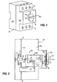
- the figure 1 schematically shows a circuit breaker according to the invention.
- the figure 2 illustrates the circuit breaker by a schematic side view.
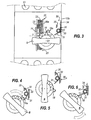
- the figure 3 represents front of various elements of the circuit breaker and the control knob in the "off” position.
- the Figures 4 to 6 show the control button in various positions, namely respectively a transient position during the motion-on movement, the "on" position and the "tripped" position.
- the circuit breaker includes (see figure 1 ) an insulating housing 10 comprising a rear portion 10a and a front portion 10b, such as a hood, assembled at the rear portion.
- a control button B pivoting about an axis X1.
- Button B can occupy three positions stable, ie a stop position marked "0", a running position marked "1" and an intermediate trigger position marked "trip".
- movable contact bridges 11 which cooperate with fixed contacts 12 for opening and closing polar paths 13 connected to upstream and downstream connection terminals 15.
- a triggering mechanism 20 is housed in the housing 10 so as to actuate polar pushers 16 capable of controlling the displacement of the contact bridges.
- the button B is rotatably connected to a rotary member of axis X1 such as a ring gear sector 17. Depending on the case, the rotary member 17 is different from the button or coincides with it.
- the crown sector 17 is provided with a radially projecting finger 18 having on one side a relatively steep side and on the other side a slope 18a.
- the sector 17 meshes with a toothed sector 21 of axis Y perpendicular to that X1 of the button, the sector 21 being connected to a system of levers 22 of the triggering mechanism 20.
- Magnetic and / or thermal actuators 19 act on the system of levers 22 to cause in the event of an electrical fault, in particular overcurrent, the switching of the system 22 and thereby the opening of the contacts.
- the triggering mechanism 20 comprises two mounting flanges 23 which extend in planes perpendicular to the Y axis and which define between them a relatively flat compartment 20a; the compartment 20a houses the system of levers 22 and a trigger spring 24 providing the necessary displacement energy to an actuating member 25 which cooperates with the polar pushers 16.
- the button B is associated with a weak spring 26 - for example spiral - used to return the button to the off position.
- a restraint with force threshold able to maintain the button B in its intermediate trigger position, is associated with the circuit breaker housing, particularly the front wall 10c of its cover 10b. This device is located according to the invention outside the compartment 20a of the trigger mechanism 20.
- the force threshold retaining device comprises a torsion spring 30 of axis X2 parallel to the axis X1 of the button.
- the torsion spring 30 comprises two end branches 31,32 and is mounted floating, that is to say angularly displaceable so as to rotate in a limited manner around the axis X2, on a bearing 33 protrusion inside the wall 10c.
- the branch 31 is an oblique retaining branch capable of angularly deflecting and intended to cooperate with the radial finger 18 of the ring gear 17.
- the branch 32 of the spring is a bearing branch which can be applied in a clockwise direction (direction of rotation). movement of the "stop” button towards “on”) against a stop 34 and counterclockwise against a stop 35.
- the stops 34 and 35 are angularly offset and provided as elements of the front wall 10c or a rim of this wall.
- the torque due to the spring 30 is greater than that due to the return spring 26 of the button, but less than that due to the sum of the forces produced by the release spring 24 and the spring recall 26.
- the operator rotates counterclockwise button B to reset the mechanism, the position of the figure 6 to an unspecified position, located a little beyond the stop position of the figure 3 .
- the operator prints the button enough effort for the finger 18 to cross the branch 31, the latter deflecting before returning to the position of the figure 3 .
- the retaining branch 31 is urged by the finger 18 in a different angular position in the stop-and-start direction and in the trigger position, to facilitate the maneuver.
- the finger 18 and / or the branch 31 of the spring has a slope facilitating the crossing of the end of the branch by the finger 18 when the button B is brought from the stop position to the on position. It has thus been represented on the figure 4 the slope 18a already described and provided on the leading edge of the finger 18.
Description
La présente invention concerne un disjoncteur électromécanique comprenant un boîtier et un mécanisme de commande doté d'un mécanisme de déclenchement apte à ouvrir des contacts polaires en réponse à la mise en oeuvre d'un organe déclencheur, notamment magnétothermique, suite à un défaut électrique, et doté d'un bouton rotatif coopérant avec le mécanisme de déclenchement et destiné à ouvrir et fermer les contacts de manière volontaire.The present invention relates to an electromechanical circuit breaker comprising a housing and a control mechanism provided with a trigger mechanism able to open polar contacts in response to the implementation of a triggering element, in particular magnetothermal, following an electrical fault, and having a rotary knob cooperating with the trigger mechanism and for opening and closing the contacts on a voluntary basis.
Le document
Dans de nombreux disjoncteurs, il est souhaitable que le bouton rotatif soit placé, en réponse à un déclenchement sur défaut, dans une position de déclenchement distincte des positions marche et arrêt, et reste maintenu dans cette position pour donner à l'opérateur une indication fiable.In many circuit breakers, it is desirable that the rotary knob be placed, in response to a fault trip, into a separate trip position from the on and off positions, and maintained in that position to give the operator a reliable indication. .
Divers dispositifs connus assurent un maintien du bouton rotatif de commande d'un disjoncteur dans une position de déclenchement intermédiaire entre les positions marche et arrêt. Ainsi le document
Les pièces de ce mécanisme sont en général montées dans un sous-ensemble plat entre deux flasques. Il apparaît souhaitable de ne pas accroître l'encombrement de ce sous-ensemble plat et donc de soustraire la fonction d'arrêt du bouton en position intermédiaire au mécanisme de déclenchement. Ainsi dans le document
Le document
Les dispositifs connus visant à arrêter le bouton rotatif en position intermédiaire impliquent le recours à des pièces encombrantes et/ou complexes.Known devices to stop the rotary knob in the intermediate position involve the use of bulky and / or complex parts.
L'invention a pour but de rendre peu encombrantes et de simplifier les dispositions prises dans un mécanisme de disjoncteur du type brièvement décrit, pour permettre au bouton de commande de prendre une position de déclenchement intermédiaire entre sa position marche et sa position arrêt.The invention aims to make it compact and simplify the arrangements made in a circuit breaker mechanism of the type briefly described, to allow the control button to take an intermediate trip position between its on position and its off position.
Selon l'invention, le dispositif de retenue du bouton rotatif en position de déclenchement comporte un ressort de torsion associé au boîtier du disjoncteur, en étant indépendant du mécanisme de déclenchement et extérieur à celui-ci. Le mécanisme de déclenchement est ainsi débarrassé de la fonction d'arrêt du bouton en position de déclenchement intermédiaire. Le terme "boîtier" désigne une partie principale de ce boîtier ou une partie rapportée à l'avant de celui-ci, telle qu'un capot.According to the invention, the retaining device of the rotary knob in the release position comprises a torsion spring associated with the casing of the circuit breaker, being independent of the triggering mechanism and external to it. The triggering mechanism is thus freed from the stop function of the button in the intermediate release position. The term "housing" refers to a main part of this housing or a portion attached to the front thereof, such as a hood.
De préférence, un élément rotatif muni d'un doigt de butée est associé au bouton, et le ressort de torsion est disposé sur une partie fixe du boîtier du disjoncteur, en présentant une branche de retenue. Le doigt de butée coopère avec la branche de retenue pour la franchir quand le bouton passe de la position arrêt à la position marche, et pour être arrêté par elle quand le mécanisme de déclenchement passe de l'état marche à l'état déclenché.Preferably, a rotary member provided with a stop finger is associated with the button, and the torsion spring is disposed on a fixed part of the circuit breaker housing, having a retaining branch. The stop finger cooperates with the retaining branch to cross it when the button moves from the stop position to the position walk, and to be stopped by it when the trigger mechanism goes from the on state to the triggered state.
Dans un mode de réalisation particulièrement simple, le ressort de torsion est monté oscillant autour de son axe, et présente une branche d'appui applicable contre deux butées du boîtier. L'attaque de la branche de retenue par le doigt de butée s'effectue alors dans une position angulaire différente selon le sens de déplacement du bouton, grâce au débattement permis par l'oscillation du ressort entre les deux butées. Il en résulte une plus grande facilité de manoeuvre du bouton.In a particularly simple embodiment, the torsion spring is mounted oscillating about its axis, and has a bearing branch applicable against two stops of the housing. The attack of the retaining branch by the stop finger then takes place in a different angular position according to the direction of movement of the button, thanks to the movement allowed by the oscillation of the spring between the two stops. This results in greater ease of operation of the button.
Lorsque le boîtier du disjoncteur présente une partie centrale ou arrière et un capot coiffant cette partie, le capot peut avantageusement présenter une paroi avant derrière laquelle sont avantageusement formés ou disposés le palier du ressort et les butées de sa branche d'appui.When the casing of the circuit breaker has a central or rear part and a cap covering this part, the cover can advantageously have a front wall behind which are advantageously formed or arranged the bearing of the spring and the stops of its support branch.
La description va être faite ci-après d'un mode de réalisation non limitatif de l'invention, en regard des dessins annexés.The description will be made hereinafter of a non-limiting embodiment of the invention, with reference to the accompanying drawings.
La
La
La
Les
The
The
The
Le disjoncteur comprend (voir
Dans le boîtier 10 du disjoncteur sont logés (voir
Le secteur de couronne 17 est doté d'un doigt en saillie radiale 18 présentant d'un côté un flanc relativement raide et de l'autre côté une pente 18a. Le secteur 17 engrène avec un secteur denté 21 d'axe Y perpendiculaire à celui X1 du bouton, le secteur 21 étant lié à un système de leviers 22 du mécanisme de déclenchement 20. Des déclencheurs magnétiques et/ou thermiques 19 agissent sur le système de leviers 22 pour provoquer en cas de défaut électrique, notamment de surintensité, la commutation du système 22 et par là l'ouverture des contacts. Le mécanisme de déclenchement 20 comprend deux joues de montage 23 qui s'étendent dans des plans perpendiculaires à l'axe Y et qui déterminent entre elles un compartiment relativement plat 20a ; le compartiment 20a loge le système de leviers 22 ainsi qu'un ressort déclencheur 24 fournissant l'énergie de déplacement nécessaire à un organe d'actionnement 25 qui coopère avec les poussoirs polaires 16. Au bouton B est associé un faible ressort 26 - par exemple du genre spiral - servant à rappeler le bouton à la position arrêt.The
Un dispositif de retenue à seuil d'effort, apte à maintenir le bouton B dans sa position intermédiaire de déclenchement, est associé au boîtier du disjoncteur, particulièrement à la paroi avant 10c de son capot 10b. Ce dispositif est situé selon l'invention à l'extérieur du compartiment 20a du mécanisme de déclenchement 20.A restraint with force threshold, able to maintain the button B in its intermediate trigger position, is associated with the circuit breaker housing, particularly the
Le dispositif de retenue à seuil d'effort comprend un ressort de torsion 30 d'axe X2 parallèle à l'axe X1 du bouton. Le ressort de torsion 30 comprend deux branches d'extrémité 31,32 et il est monté flottant, c'est-à-dire angulairement déplaçable de façon à pivoter en bloc de manière limitée autour de l'axe X2, sur un palier 33 en saillie à l'intérieur de la paroi 10c. La branche 31 est une branche de retenue oblique capable de fléchir angulairement et destinée à coopérer avec le doigt radial 18 de la couronne dentée 17. La branche 32 du ressort est une branche d'appui qui peut s'appliquer en sens horaire (sens de déplacement du bouton de "arrêt" vers "marche") contre une butée 34 et en sens antihoraire contre une butée 35. Les butées 34 et 35 sont décalées angulairement et prévues en tant qu'éléments de la paroi avant 10c ou d'un rebord de cette paroi.The force threshold retaining device comprises a
Vu de l'élément rotatif portant le doigt 18, le couple dû au ressort 30 est supérieur à celui dû au ressort de rappel 26 du bouton, mais inférieur à celui dû à la somme des efforts produits par le ressort de déclenchement 24 et le ressort de rappel 26.Seen from the rotary member carrying the
Le fonctionnement du dispositif de retenue du bouton va à présent être décrit en regard des
Pour passer de l'état arrêt indiqué
Lorsqu'une surintensité est constatée par un déclencheur 19, celui-ci actionne le système 22 qui ouvre les contacts et fait pivoter le secteur denté 21, celui-ci entraînant la couronne dentée 17 en sens antihoraire jusqu'à l'application du flanc raide du doigt 18 sur la branche de retenue 31. Un pivotement du ressort 30 a lieu, sous l'effet des ressorts de déclenchement 24 et de rappel 26, jusqu'à application de l'extrémité de la branche 32 du ressort 30 contre la butée 34 - face interne de la paroi 10c - (voir
Lors d'une opération manuelle de réarmement, l'opérateur fait tourner en sens antihoraire le bouton B pour réarmer le mécanisme, de la position de la
Le doigt 18 et/ou la branche 31 du ressort présente une pente facilitant le franchissement de l'extrémité de la branche par le doigt 18 quand le bouton B est amené de la position arrêt à la position marche. On a ainsi représenté sur la
Claims (6)
- Circuit breaker equipped with a casing (10) and with a control mechanism (20), the mechanism comprising- a tripping unit which is sensitive to an electrical fault,- a trip mechanism (22) which is capable of opening the contacts in response to implementation of the tripping unit,- a rotary knob (B) intended to open and close the contacts by a manual action, while assuming an open position and a closed position respectively, implementation of the trip mechanism placing the rotary knob in an intermediate trip position between its open and closed positions,- a device for holding the rotary knob (B) in the trip position, characterized by the fact that the device for holding the rotary knob (B) in the trip position comprises a torsion spring (30) associated with the casing (10) of the circuit breaker, this holding device being independent of the trip mechanism (22) and external thereto.
- Circuit breaker according to Claim 1, characterized by the fact that the holding device comprises a rotary element (17) associated with the knob (B) and provided with a stop finger (18) and that the torsion spring (30) has an oblique holding arm (31) disposed over a fixed portion of the casing of the circuit breaker, and by the fact that the stop finger (18) cooperates with the holding arm (31) in order to cross it when the knob passes from the off position to the on position and to be stopped by this arm when the trip mechanism (20) passes from the on state to the tripped state.
- Circuit breaker according to Claim 2, wherein the trip mechanism comprises a trip spring (24), characterized by the fact that a spring (26) for returning to the off position is associated with the knob (B) and that, in view of the fact that the rotary element carries the stop finger (18), the torque due to the resilient unit (30) is greater than the torque due to the return spring but less than the sum of the torques due to the trip spring (24) and the return spring (26).
- Circuit breaker according to Claim 2, characterized by the fact that the holding arm (31) of the torsion spring can be urged by the stop finger (18) into an angular position of the arm that differs in the off-on direction and in the trip position.
- Circuit breaker according to Claim 4, characterized by the fact that the torsion spring (30) is mounted so as to oscillate on a bearing (33) of a cover (10b) of the casing of the circuit breaker and has a support arm (32) which can be applied against two fixed stops (34, 35) in one direction of oscillation and in the other direction of oscillation respectively, the bearing of the spring and the stops of the support arm being formed or disposed behind the wall (10c) of the cover.
- Circuit breaker according to Claim 4, characterized by the fact that the stop finger (18) has, in the off-on direction, a ramp (18a) facilitating engagement of the holding arm (31).
Applications Claiming Priority (2)
| Application Number | Priority Date | Filing Date | Title |
|---|---|---|---|
| FR0109054A FR2827076B1 (en) | 2001-07-06 | 2001-07-06 | CIRCUIT BREAKER AND ITS CONTROL MECHANISM |
| FR0109054 | 2001-07-06 |
Publications (2)
| Publication Number | Publication Date |
|---|---|
| EP1274109A1 EP1274109A1 (en) | 2003-01-08 |
| EP1274109B1 true EP1274109B1 (en) | 2008-03-26 |
Family
ID=8865253
Family Applications (1)
| Application Number | Title | Priority Date | Filing Date |
|---|---|---|---|
| EP20020077776 Expired - Fee Related EP1274109B1 (en) | 2001-07-06 | 2002-07-03 | Circuit breaker and it's opperating mechanism |
Country Status (4)
| Country | Link |
|---|---|
| EP (1) | EP1274109B1 (en) |
| DE (1) | DE60225765T2 (en) |
| ES (1) | ES2301604T3 (en) |
| FR (1) | FR2827076B1 (en) |
Cited By (2)
| Publication number | Priority date | Publication date | Assignee | Title |
|---|---|---|---|---|
| EP1906428A3 (en) * | 2006-09-27 | 2008-12-31 | Siemens Aktiengesellschaft | Switch rotary drive |
| US8816802B2 (en) | 2012-02-08 | 2014-08-26 | Siemens Aktiengesellschaft | Auxiliary tripping device for an electrical switching device and electrical switching device |
Families Citing this family (6)
| Publication number | Priority date | Publication date | Assignee | Title |
|---|---|---|---|---|
| DE102006057648A1 (en) * | 2006-12-07 | 2008-06-12 | Abb Ag | Switching device with rotary handle |
| DE102006057649B4 (en) * | 2006-12-07 | 2021-03-04 | Abb Schweiz Ag | Switching device |
| GB2445970A (en) * | 2007-01-24 | 2008-07-30 | I C Innovations Ltd | Door display |
| KR100876408B1 (en) * | 2007-07-12 | 2008-12-31 | 엘에스산전 주식회사 | Air circuit breaker with mechanical trip indicating mechanism |
| DE102009048933A1 (en) * | 2009-07-17 | 2011-01-27 | Abb Ag | Switching device with rotary handle |
| FR3051593B1 (en) * | 2016-05-23 | 2019-10-04 | Schneider Electric Industries Sas | DEVICE FOR SIGNALING AN ELECTRICAL FAULT IN AN ELECTRICAL PROTECTION APPARATUS, AND ELECTRICAL PROTECTION APPARATUS COMPRISING SUCH A DEVICE |
Family Cites Families (6)
| Publication number | Priority date | Publication date | Assignee | Title |
|---|---|---|---|---|
| FR2560713B1 (en) * | 1984-03-02 | 1988-04-29 | Merlin Gerin | MECHANISM FOR QUICK CLOSING OF A MINIATURE CIRCUIT BREAKER |
| FR2671907B1 (en) * | 1991-01-17 | 1995-05-12 | Telemecanique | CIRCUIT BREAKER WITH VARIABLE MANUAL CONTROL. |
| FR2685976A1 (en) * | 1992-01-07 | 1993-07-09 | Telemecanique | MECHANISM FOR CURRENT SWITCHING APPARATUS. |
| US5296664A (en) * | 1992-11-16 | 1994-03-22 | Westinghouse Electric Corp. | Circuit breaker with positive off protection |
| DE19703959C1 (en) * | 1997-02-03 | 1998-04-23 | Siemens Ag | Switching device e.g. circuit breaker or contactor |
| US6031438A (en) * | 1998-10-16 | 2000-02-29 | Airpax Corporation, Llc | Mid trip stop for circuit breaker |
-
2001
- 2001-07-06 FR FR0109054A patent/FR2827076B1/en not_active Expired - Fee Related
-
2002
- 2002-07-03 DE DE2002625765 patent/DE60225765T2/en not_active Expired - Lifetime
- 2002-07-03 ES ES02077776T patent/ES2301604T3/en not_active Expired - Lifetime
- 2002-07-03 EP EP20020077776 patent/EP1274109B1/en not_active Expired - Fee Related
Cited By (2)
| Publication number | Priority date | Publication date | Assignee | Title |
|---|---|---|---|---|
| EP1906428A3 (en) * | 2006-09-27 | 2008-12-31 | Siemens Aktiengesellschaft | Switch rotary drive |
| US8816802B2 (en) | 2012-02-08 | 2014-08-26 | Siemens Aktiengesellschaft | Auxiliary tripping device for an electrical switching device and electrical switching device |
Also Published As
| Publication number | Publication date |
|---|---|
| DE60225765T2 (en) | 2009-04-09 |
| FR2827076B1 (en) | 2004-03-12 |
| FR2827076A1 (en) | 2003-01-10 |
| DE60225765D1 (en) | 2008-05-08 |
| EP1274109A1 (en) | 2003-01-08 |
| ES2301604T3 (en) | 2008-07-01 |
Similar Documents
| Publication | Publication Date | Title |
|---|---|---|
| EP0962952B1 (en) | Electric power cut-off device comprising a differential release device and a circuit breaker equiped with such a device | |
| EP1975971B1 (en) | Device for controlling an electric protection device and electric protection device including same | |
| FR2578354A1 (en) | CIRCUIT BREAKER THAT CAN OPERATE AS A SWITCH | |
| EP0610143A1 (en) | Mechanical and electrical locking device for a remote control unit of a modular circuit breaker | |
| EP1170769B1 (en) | Snap closing mechanism for modular circuit breaker | |
| CA2186772A1 (en) | Control and display device for protection switches | |
| EP0935272B1 (en) | Trip device for a circuit breaker with an electrical fault signalisation | |
| EP1274109B1 (en) | Circuit breaker and it's opperating mechanism | |
| FR2863403A1 (en) | Electrical protection apparatus e.g. circuit breaker, tripping signaling device, has moving unit activating signaling unit to signal tripping state of circuit breaker, when opening of fixed and movable contacts is due to electric fault | |
| FR2923942A1 (en) | DEVICE FOR CONTROLLING AN ELECTRICAL CUTTING APPARATUS AND AN ELECTRICAL CUTTING APPARATUS COMPRISING IT | |
| FR2998415A1 (en) | MAGNETOTHERMIC TRIGGER TRIPPING OF A POLYPHASE CIRCUIT BREAKER | |
| EP1965405B1 (en) | Offset activation device for a circuit breaker including a trigger assistance device | |
| EP0547928B1 (en) | Protective switch | |
| BE1000208A6 (en) | Drive device for the engagement and remote activation of an automatic switch. | |
| EP0571258B1 (en) | Protective switching device | |
| EP2717284B1 (en) | Operating device of an electric protection apparatus and electric protection apparatus comprising same | |
| EP2365510B1 (en) | Circuit breaker | |
| EP0311668A1 (en) | Protective switching device with simplified tripping mechanism | |
| FR2503930A1 (en) | MINIMUM VOLTAGE TRIGGER FOR POWER CIRCUIT BREAKERS | |
| EP0310469B1 (en) | Protective switch with a screen for cutting the arc | |
| EP0901142A1 (en) | Device for indicating an electrical fault in a switching device, like a differential circuit breaker | |
| EP0685867A1 (en) | Differential release device | |
| EP2642502B1 (en) | Trip unit for an electric protection apparatus and electric protection apparatus comprising one such unit | |
| EP3309813A1 (en) | Differential electric switching device comprising a differential function test device | |
| FR2621417A1 (en) | PROTECTION SWITCH WITH ARC SHUTDOWN SCREEN |
Legal Events
| Date | Code | Title | Description |
|---|---|---|---|
| PUAI | Public reference made under article 153(3) epc to a published international application that has entered the european phase |
Free format text: ORIGINAL CODE: 0009012 |
|
| AK | Designated contracting states |
Kind code of ref document: A1 Designated state(s): AT BE BG CH CY CZ DE DK EE ES FI FR GB GR IE IT LI LU MC NL PT SE SK TR |
|
| AX | Request for extension of the european patent |
Free format text: AL;LT;LV;MK;RO;SI |
|
| 17P | Request for examination filed |
Effective date: 20030127 |
|
| AKX | Designation fees paid |
Designated state(s): DE ES IT |
|
| GRAP | Despatch of communication of intention to grant a patent |
Free format text: ORIGINAL CODE: EPIDOSNIGR1 |
|
| GRAS | Grant fee paid |
Free format text: ORIGINAL CODE: EPIDOSNIGR3 |
|
| GRAA | (expected) grant |
Free format text: ORIGINAL CODE: 0009210 |
|
| AK | Designated contracting states |
Kind code of ref document: B1 Designated state(s): DE ES IT |
|
| REF | Corresponds to: |
Ref document number: 60225765 Country of ref document: DE Date of ref document: 20080508 Kind code of ref document: P |
|
| REG | Reference to a national code |
Ref country code: ES Ref legal event code: FG2A Ref document number: 2301604 Country of ref document: ES Kind code of ref document: T3 |
|
| PLBE | No opposition filed within time limit |
Free format text: ORIGINAL CODE: 0009261 |
|
| STAA | Information on the status of an ep patent application or granted ep patent |
Free format text: STATUS: NO OPPOSITION FILED WITHIN TIME LIMIT |
|
| 26N | No opposition filed |
Effective date: 20081230 |
|
| REG | Reference to a national code |
Ref country code: DE Ref legal event code: R084 Ref document number: 60225765 Country of ref document: DE |
|
| PGFP | Annual fee paid to national office [announced via postgrant information from national office to epo] |
Ref country code: ES Payment date: 20190809 Year of fee payment: 18 Ref country code: IT Payment date: 20190718 Year of fee payment: 18 |
|
| PGFP | Annual fee paid to national office [announced via postgrant information from national office to epo] |
Ref country code: DE Payment date: 20200622 Year of fee payment: 19 |
|
| REG | Reference to a national code |
Ref country code: ES Ref legal event code: FD2A Effective date: 20211126 |
|
| PG25 | Lapsed in a contracting state [announced via postgrant information from national office to epo] |
Ref country code: ES Free format text: LAPSE BECAUSE OF NON-PAYMENT OF DUE FEES Effective date: 20200704 |
|
| REG | Reference to a national code |
Ref country code: DE Ref legal event code: R119 Ref document number: 60225765 Country of ref document: DE |
|
| PG25 | Lapsed in a contracting state [announced via postgrant information from national office to epo] |
Ref country code: IT Free format text: LAPSE BECAUSE OF NON-PAYMENT OF DUE FEES Effective date: 20200703 Ref country code: DE Free format text: LAPSE BECAUSE OF NON-PAYMENT OF DUE FEES Effective date: 20220201 |