EP1273796B1 - Hochdruck-Kraftstoffpumpe, insbesondere für direkteinspritzende Brennkraftmaschine, sowie Kraftstoffsystem und Brennkraftmaschine - Google Patents
Hochdruck-Kraftstoffpumpe, insbesondere für direkteinspritzende Brennkraftmaschine, sowie Kraftstoffsystem und Brennkraftmaschine Download PDFInfo
- Publication number
- EP1273796B1 EP1273796B1 EP02009419A EP02009419A EP1273796B1 EP 1273796 B1 EP1273796 B1 EP 1273796B1 EP 02009419 A EP02009419 A EP 02009419A EP 02009419 A EP02009419 A EP 02009419A EP 1273796 B1 EP1273796 B1 EP 1273796B1
- Authority
- EP
- European Patent Office
- Prior art keywords
- valve
- pressure
- pump
- fuel
- fuel pump
- Prior art date
- Legal status (The legal status is an assumption and is not a legal conclusion. Google has not performed a legal analysis and makes no representation as to the accuracy of the status listed.)
- Expired - Lifetime
Links
- 239000000446 fuel Substances 0.000 title claims description 97
- 238000002485 combustion reaction Methods 0.000 title claims description 19
- 238000002347 injection Methods 0.000 title claims description 7
- 239000007924 injection Substances 0.000 title claims description 7
- 238000005086 pumping Methods 0.000 description 6
- 238000004519 manufacturing process Methods 0.000 description 5
- 230000006835 compression Effects 0.000 description 4
- 238000007906 compression Methods 0.000 description 4
- 238000010586 diagram Methods 0.000 description 3
- 238000011161 development Methods 0.000 description 2
- 230000018109 developmental process Effects 0.000 description 2
- 239000002828 fuel tank Substances 0.000 description 2
- 230000002996 emotional effect Effects 0.000 description 1
- 230000002349 favourable effect Effects 0.000 description 1
- 238000009434 installation Methods 0.000 description 1
- 239000002184 metal Substances 0.000 description 1
- 230000001105 regulatory effect Effects 0.000 description 1
Images


Classifications
-
- F—MECHANICAL ENGINEERING; LIGHTING; HEATING; WEAPONS; BLASTING
- F04—POSITIVE - DISPLACEMENT MACHINES FOR LIQUIDS; PUMPS FOR LIQUIDS OR ELASTIC FLUIDS
- F04B—POSITIVE-DISPLACEMENT MACHINES FOR LIQUIDS; PUMPS
- F04B49/00—Control, e.g. of pump delivery, or pump pressure of, or safety measures for, machines, pumps, or pumping installations, not otherwise provided for, or of interest apart from, groups F04B1/00 - F04B47/00
- F04B49/22—Control, e.g. of pump delivery, or pump pressure of, or safety measures for, machines, pumps, or pumping installations, not otherwise provided for, or of interest apart from, groups F04B1/00 - F04B47/00 by means of valves
- F04B49/225—Control, e.g. of pump delivery, or pump pressure of, or safety measures for, machines, pumps, or pumping installations, not otherwise provided for, or of interest apart from, groups F04B1/00 - F04B47/00 by means of valves with throttling valves or valves varying the pump inlet opening or the outlet opening
-
- F—MECHANICAL ENGINEERING; LIGHTING; HEATING; WEAPONS; BLASTING
- F02—COMBUSTION ENGINES; HOT-GAS OR COMBUSTION-PRODUCT ENGINE PLANTS
- F02M—SUPPLYING COMBUSTION ENGINES IN GENERAL WITH COMBUSTIBLE MIXTURES OR CONSTITUENTS THEREOF
- F02M59/00—Pumps specially adapted for fuel-injection and not provided for in groups F02M39/00 -F02M57/00, e.g. rotary cylinder-block type of pumps
- F02M59/20—Varying fuel delivery in quantity or timing
- F02M59/36—Varying fuel delivery in quantity or timing by variably-timed valves controlling fuel passages to pumping elements or overflow passages
- F02M59/366—Valves being actuated electrically
-
- F—MECHANICAL ENGINEERING; LIGHTING; HEATING; WEAPONS; BLASTING
- F04—POSITIVE - DISPLACEMENT MACHINES FOR LIQUIDS; PUMPS FOR LIQUIDS OR ELASTIC FLUIDS
- F04B—POSITIVE-DISPLACEMENT MACHINES FOR LIQUIDS; PUMPS
- F04B1/00—Multi-cylinder machines or pumps characterised by number or arrangement of cylinders
- F04B1/04—Multi-cylinder machines or pumps characterised by number or arrangement of cylinders having cylinders in star- or fan-arrangement
- F04B1/0404—Details or component parts
- F04B1/0452—Distribution members, e.g. valves
Definitions
- the invention relates to a high-pressure fuel pump, in particular for direct injection internal combustion engines, with a housing having a low pressure inlet and a High pressure outlet, with one in the housing existing pump room, which with the low-pressure inlet and the high-pressure outlet is connectable, with a control valve, which directly the pump room with the low-pressure inlet can connect and opens to the low-pressure inlet, and with a check valve with a separate from the control valve Valve element which between low-pressure inlet and Pump room is arranged and directly to the pump room opens.
- Such a high-pressure fuel pump is known from DE 198 34 120 A1 known.
- This high pressure fuel pump is included Fuel supply systems with two series connected Fuel pumps used. From the pump room branches on the one hand Flow channel, which via a check valve to a Low pressure inlet leads. On the other hand leads another Flow channel from the pump chamber to a control valve, which with another flow channel in the housing of the high-pressure fuel pump which is also connected to the low pressure inlet leads. On the outlet side, the pump room is also over a check valve connected to a high pressure outlet.
- the control valve be opened during a delivery stroke of the pump piston.
- the pump space is the low-pressure inlet opened and no more fuel to the high pressure outlet promoted.
- control valve could also be at the beginning of a Delivery stroke of the pump piston to be opened.
- the control the delivery rate by a variation of the delivery end has however, several advantages:
- control valve can be made simpler, because the flow cross-section to be controlled considerably smaller can be executed. Since the pump piston mostly from a Drive cam is driven, the load of the falls Drive cam lower, since the promotion before the upper Dead center of the pump piston is terminated (at top dead center of the pump piston occurs due to the small radius of curvature the highest Hertzian pressure). Finally, it turns out still a cost advantage in that the control of the Control valve can be done via a switching power amplifier.
- EP 0 078 983 A1 and EP 0 816 672 A2 describe a High pressure pump with a control valve, which with a Inlet valve is connected in series.
- the object of the present invention is a high-pressure fuel pump of the type mentioned at the beginning, that it builds easier overall and thus cheaper can be produced.
- This task is in a high-pressure fuel pump of mentioned type achieved in that the Check valve and the control valve in a common Valve module are housed, which at least partially inserted into the pump housing and for the Control valve and the check valve a common Having connection to the low-pressure inlet out, and that the Elements of the check valve and the elements of the Control valve to each other coaxially arranged in the valve module are.
- Inlet valve through which the fuel from the low pressure inlet flows into the pump room during a suction stroke
- Control valve which towards the end of a delivery stroke of the Pump piston opens, integrated into a common unit.
- This unit can be pre-assembled. Due to the better accessibility, such an assembly is easier perform at a cost advantage, but also at a cost Quality increase leads.
- High-pressure fuel pump only a few flow channels required because the common valve module for the Check valve and the control valve a common Having connection to the low pressure inlet out. to Manufacture of the housing of the high-pressure fuel pump are thus less processing steps required what the Production costs for the high-pressure fuel pump according to the invention lowers.
- the Control valve is radially inward and the check valve a Includes a plurality of flow channels, which radially outward to at least a portion of the control valve in the valve module are provided. Through this plurality of flow channels becomes a comparatively large flow cross section for the Check valve created so that during a suction stroke the pump piston rapid filling of the pump chamber possible is.
- the flow channels preferably interconnected by an annulus.
- the Control valve in turn is at least with its valve element radially inside the flow channels.
- valve element comprises.
- Such Valve element is as well as the associated valve seat easy to manufacture.
- valve dynamics of the check valve is the better, depending less the mass of the valve element of the check valve is. This is taken into account in that training, in the valve element of the check valve is a thin one Includes platelets.
- check valve as a double seat valve be educated. In this case already stands at low Valve lift a large flow area available.
- the high-pressure fuel pump comprises Valve module to the pump room at least one Support section, on which a biasing element is supported, which the valve element of the check valve against the associated valve seat acted upon.
- the bias of the Biasing element is preferably just so strong that the valve element of the check valve already at a low pressure difference from the associated valve seat lifts. Is the support section, as proposed, on Valve module arranged, the complete unit can off Check valve and control valve are pre-assembled, which reduces the production costs again.
- the invention also relates to a fuel system with a Fuel tank, with at least one fuel injection device, which the fuel directly into the Injecting combustion chamber of an internal combustion engine, with at least one high-pressure fuel pump, and with a Fuel manifold to which the fuel injector connected.
- Such a fuel system is used in internal combustion engines used with direct fuel injection.
- the pressure in the fuel rail which is commonly referred to as "Rail” is referred to as the high-pressure fuel pump applied.
- the invention further relates to an internal combustion engine with at least one combustion chamber into which the fuel injected directly.
- an internal combustion engine with at least one combustion chamber into which the fuel injected directly.
- To the internal combustion engine overall easier to build and their production to make cheaper, as well as to the operation of the To make the internal combustion engine more reliable suggested that they have a fuel system of the above has mentioned type.
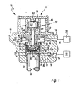
- Fig. 1 carries a high-pressure fuel pump in total the reference number 10. From her is in the figure only one End area shown.
- the high pressure fuel pump 10 comprises a housing 12 into which a stepped bore 14 is introduced. Transversal to the longitudinal axis of Stepped bore 14 are in the housing 12 also two Flow channels 16 and 18 available.
- the upper in Fig. 1 Flow channel 16 leads to a low-pressure inlet 20 for the fuel.
- the lower in Fig. 1 flow channel 18th leads to a high-pressure outlet 22.
- a pump piston 26 guided axially movable.
- a valve housing 30 is inserted in an upper area 28 of the Stepped bore 14. This is opposite the stepped bore 14 by an O-ring seal 32 sealed, which in an annular groove (without Reference numeral) inserted in the wall of the stepped bore 14 is.
- Between the valve housing 30 and the pump piston 26th is a pump room 34 available.
- valve housing 30 In the valve housing 30, a check valve 36 and housed a control valve 38. On the exact Training will be referred to in detail below.
- actuating unit 40 On the valve housing 30 is an actuating unit 40 placed.
- the operating unit 40 is opposite to Pump housing 12 sealed by an O-ring seal 42, in an annular groove (without reference numeral) in the top the pump housing 12 is inserted.
- the operating unit 40 is about screws (without reference numeral) on the pump housing 12 attached. Your task is detailed below explained.
- the attachment of the actuator unit 40 am Valve housing 30 is inseparable via a flange 41st Die Actuator 40, the control valve 38, the Non-return valve 36 and the valve housing 30 form together a valve module 44th
- the valve housing 30 has a total cylindrical shape. It becomes in its longitudinal direction of a centric Stepped bore 46 interspersed.
- a centric Stepped bore 46 interspersed in the stepped bore 46 is in Fig. 1 from above a rod-shaped valve element 48th introduced, which with a rounded end with a in Fig. 1 lower portion of the stepped bore 36 existing Valve seat 50 cooperates.
- the valve element 48 and the valve seat 50 are part of the control valve 38.
- valve element 48 extends upwardly out of the Valve housing 30 out in the actuator 40th into it.
- a cylindrical armature 52 is attached at the end remote from the valve seat 50 of the Valve element 48 .
- a lid 56 closes the operating unit 40 upwards down.
- a annular magnet 86 is provided, which at a Energizing the armature 52 moves in Fig. 1 down, so that the valve element 48 is pressed into the valve seat 50 becomes.
- the stepped bore 46 forms a flow channel 58, which opens into the pump chamber 34.
- the stepped bore 46 has a larger diameter than the valve element 48, so that a Valve chamber 60 is formed. This is about a majority of radially extending flow channels 62 with a circumferential groove 64 connected in the outer wall of the Valve housing 30 is introduced. In the in Fig. 1 shown installation position is the groove 64 at the height of a extended portion 66 of the stepped bore 14 in Pump housing 12. As a result, an annular space 68 is formed. From this branches to the low pressure inlet 20 out of the already introduced above Stömungskanal 16 from.
- the check valve 36 is constructed as follows: In the valve housing 30 extend from the circumferential groove 64th a plurality of substantially axial flow channels 70 obliquely down and slightly radially inward. In the in Fig. 1 illustrated embodiment are a total of four in Circumferentially arranged evenly distributed Flow channels 70 present, of which in Fig. 1 two are visible. The flow channels 70 open into the Bottom of the valve body 30. The openings of the Flow channels 70 in the bottom of the valve housing 30th There are surrounded by an annular valve seat 72. This consists of a valve housing 30 coaxial and radially inner ring land 72a and a likewise to Valve body 30 coaxial and radially outer annular land 72b.
- a small force Compression spring 74 On the annular valve seat 72 on the bottom of the Valve housing 30 is powered by a small force Compression spring 74 a disc-annular valve element 76th pressed. In the disc-annular valve element 76th it is a thin metal plate.
- the Compression spring 74 is supported on an axially extending annular support member 78 from. This is with his upper edge welded to the valve housing 30. At his In Fig. 1 lower end, the support member 78 a radially inwardly facing annular web 80 on which the Compression spring 74 is applied.
- the disc-ring-shaped Valve element 76 of the check valve 36 are above the Circumference distributed radial recesses 82 available. in the Support member 78 are corresponding, not in the figure visible openings provided.
- Fig. 1 it can be seen on the one hand, the elements of the check valve 36, so the Plurality of axial flow channels 70 and annular Valve seats 72, the compression spring 74, the disc-annular Valve element 76 and the support member 78, coaxial with the Elements of the control valve 38, ie in particular the Stepped bore 46 in the valve housing 30, the valve element 48th and the valve seat 50. Furthermore, recognizes one, that the circumferential groove 64 has a common connection the check valve 36 and the control valve 38 for Low-pressure inlet forms.
- Check valve 84 is a normal one spring loaded ball valve leading to the high pressure outlet 22 opens.
- the high pressure fuel pump 10 operates as follows (See also Fig. 2 - 6, it should be noted that in particular in FIGS. 2 to 4 for reasons of illustration not all parts and reference signs are shown; Further, in Figures 2 to 4, the control valve 38 and the check valve 36 in one of Figure 1 different orientation relative to the longitudinal axis of Piston 26 shown):
- Figs. 2-4 is the Pump piston 26 driven by a cam 88, which on a clockwise rotating shaft 90 is attached.
- the shaft 90 is directly from a crankshaft of an associated internal combustion engine driven.
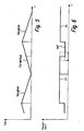
- the high-pressure fuel pump 10 moves the Pump piston 26 down (suction stroke, see Fig. 5). This increases the pump space 34.
- the pressure in Pumping chamber 34 is in this operating state of the high-pressure fuel pump 10 lower than the pressure at the high pressure outlet 22, so that the check valve 84 is closed is.
- the magnet 86 of the control valve 38 is in this Operating state of the high pressure fuel pump 10 energized.
- the valve element 48 against the valve seat 50th pressed; the control valve 38 is thus closed (see. Fig. 6, left area).
- the fuel flows on the one hand between the disc-annular valve element 76 and the radial inner ring land 72a and the central opening (without Reference numeral) in the disc-annular valve element 76 for Pumping room 34.
- fuel also flows between the radially outer ring land 72b and the disc-annular valve element 76 through the radial Recesses 82 and the corresponding recesses in the Support member 78 in the pump chamber 34.
- that is Check valve 36 thus formed as a double seat valve.
- the pressure of the pump chamber 34 increases enclosed fuel. This happens until the pressure difference between in the pump room 34th enclosed fuel and fuel at High-pressure outlet 22 is so large that the check valve 84 opens. Then the fuel flows out of the pumping space 34 through the lower flow passage 18 to the high-pressure outlet 22 of the high-pressure fuel pump 10 out.
- the opening of the control valve 38 towards the end of a delivery stroke is otherwise shown in Fig. 4.
- a suitable Choice of the time at which the control valve 38 during opens a delivery stroke which can during a delivery stroke pumped from the pumping chamber 34 to the high-pressure outlet 22 towards Fuel quantity to be adjusted.
- Fig. 7 is a not according to the invention Embodiment of a High pressure fuel pump 10 shown.
- Fig. 8 shows an internal combustion engine 92, in which a Fuel system 94 is installed. This includes one Fuel tank 96, from which an electric Fuel pump 98 supplies the fuel to a low pressure inlet 20 promotes a high-pressure fuel pump 10.
- the High-pressure fuel pump 10 is in the in Figs. 1-6 or constructed in Fig. 7 illustrated type.
- the fuel rail has that Reference numeral 100.
- To the fuel rail 100 are several high-pressure injectors, for example Injectors 102, connected. These inject the Fuel directly into corresponding combustion chambers 104 a.
- Of the Pressure in the fuel rail 100 is from a Pressure sensor 106 detected. This provides appropriate Signals to a control and / or regulating device 108.
- the magnetic control valve in FIG. 8) controls without reference numeral) of the high pressure fuel pump 10 to the pressure in the fuel rail 100 in the sense a closed system on a desired To keep level.
Landscapes
- Engineering & Computer Science (AREA)
- Mechanical Engineering (AREA)
- General Engineering & Computer Science (AREA)
- Chemical & Material Sciences (AREA)
- Combustion & Propulsion (AREA)
- Fuel-Injection Apparatus (AREA)
Description
- Fig. 1:
- einen teilweisen Schnitt durch einen Bereich eines ersten Ausführungsbeispiels einer Hochdruck-Kraftstoffpumpe;
- Fig. 2 bis 4:
- eine stark vereinfachte Darstellung des Bereichs von Fig. 1 zu unterschiedlichen Zeitpunkten während des Betriebs der Hochdruck-Kraftstoffpumpe;
- Fig. 5:
- ein Diagramm, in dem das Fördervolumen der Hochdruck-Kraftstoffpumpe der Fig. 1 - 4 über der Zeit aufgetragen ist;
- Fig. 6:
- ein Diagramm, in dem der Öffnungszustand eines Steuerventils der Hochdruck-Kraftstoffpumpe der Fig. 1 - 4 über der Zeit aufgetragen ist;
- Fig. 7:
- eine schematisierte und teilweise geschnittene Darstellung eines Bereichs eines nicht erfindungsgemäßen Ausführungsbeispiels einer Hochdruck-Kraftstoffpumpe; und
- Fig. 8:
- ein schematisiertes Blockschaltbild einer Brennkraftmaschine mit einem Kraftstoffsystem und einer Hochdruck-Kraftstoffpumpe gemäß Fig. 1.
Claims (9)
- Hochdruck-Kraftstoffpumpe (10), insbesondere für direkteinspritzende Brennkraftmaschinen (92), mit einem Gehäuse (12), welches einen Niederdruck-Einlass (20) und einen Hochdruck-Auslass (22) aufweist, mit einem in dem Gehäuse (12) vorhandenen Pumpraum (34), welcher mit dem Niederdruck-Einlass (20) und dem Hochdruck-Auslass (22) verbindbar ist, mit einem Steuerventil (38), welches den Pumpraum (34) mit dem Niederdruck-Einlass (20) unmittelbar verbinden kann und zum Niederdruck-Einlass (20) hin öffnet, und mit einem Rückschlagventil (36) mit einem vom Steuerventil (38) separaten Ventilelement (76), welches zwischen Niederdruck-Einlass (20) und Pumpraum (34) angeordnet ist und unmittelbar zum Pumpraum (34) hin öffnet, dadurch gekennzeichnet, dass das Rückschlagventil (36) und das Steuerventil (38) in einem gemeinsamen Ventilmodul (44) untergebracht sind, welches wenigstens bereichsweise in das Pumpengehäuse (12) eingesetzt ist und für das Steuerventil (38) und das Rückschlagventil (36) einen gemeinsamen Anschluss (64) zum Niederdruck-Einlass (20) hin aufweist, und dass die Elemente des Rückschlagventils (36) und die Elemente des Steuerventils (38) zueinander koaxial in dem Ventilmodul (44) angeordnet sind.
- Hochdruck-Kraftstoffpumpe (10) nach Anspruch 1, dadurch gekennzeichnet, dass das Steuerventil (38) radial innen liegt und das Rückschlagventil (36) eine Mehrzahl von Strömungskanälen (70) umfasst, welche radial außen um mindestens einen Bereich des Steuerventils (38) im Ventilmodul (44) vorgesehen sind.
- Hochdruck-Kraftstoffpumpe (10) nach Anspruch 2, dadurch gekennzeichnet, dass das Rückschlagventil (36) ein scheibenringförmiges Ventilelement (76) umfasst.
- Hochdruck-Kraftstoffpumpe (10) nach einem der vorhergehenden Ansprüche, dadurch gekennzeichnet, dass das Ventilelement des Rückschlagventils (36) ein dünnes Plättchen (76) umfasst.
- Hochdruck-Kraftstoffpumpe nach einem der vorhergehenden Ansprüche, dadurch gekennzeichnet, dass das Rückschlagventil (36) als Doppelsitzventil ausgebildet ist.
- Hochdruck-Kraftstoffpumpe nach einem der vorhergehenden Ansprüche, dadurch gekennzeichnet, dass das Ventilmodul (44) zum Pumpraum (34) hin mindestens einen Stützabschnitt (78) umfasst, an dem sich ein Vorspannelement (74) abstützt, welches das Ventilelement (76) des Rückschlagventils (36) gegen den zugehörigen Ventilsitz (72) beaufschlagt.
- Hochdruck-Kraftstoffpumpe (10) nach Anspruch 6, dadurch gekennzeichnet, dass der Stützabschnitt (78) einstückig mit einem gemeinsamen Ventilgehäuse (30) ausgebildet ist.
- Kraftstoffsystem (94) mit einem Kraftstoffbehälter (96), mit mindestens einer Kraftstoff-Einspritzvorrichtung (102), welche den Kraftstoff direkt in den Brennraum (104) einer Brennkraftmaschine (92) einspritzt, mit mindestens einer Hochdruck-Kraftstoffpumpe (10), und mit einer Kraftstoff-Sammelleitung (100), an die die Kraftstoff-Einspritzvorrichtung (102) angeschlossen ist, dadurch gekennzeichnet, dass die Hochdruck-Kraftstoffpumpe (10) nach einem der Ansprüche 1 bis 7 ausgebildet ist.
- Brennkraftmaschine (92) mit mindestens einem Brennraum (104), in den der Kraftstoff direkt eingespritzt wird, dadurch gekennzeichnet, dass sie ein Kraftstoffsystem (94) nach Anspruch 8 aufweist.
Applications Claiming Priority (2)
| Application Number | Priority Date | Filing Date | Title |
|---|---|---|---|
| DE10124238A DE10124238A1 (de) | 2001-05-18 | 2001-05-18 | Hochdruck-Kraftstoffpumpe, insbesondere für direkteinspritzende Brennkraftmaschinen, sowie Kraftstoffsystem und Brennkraftmaschine |
| DE10124238 | 2001-05-18 |
Publications (3)
| Publication Number | Publication Date |
|---|---|
| EP1273796A2 EP1273796A2 (de) | 2003-01-08 |
| EP1273796A3 EP1273796A3 (de) | 2003-11-19 |
| EP1273796B1 true EP1273796B1 (de) | 2005-06-01 |
Family
ID=7685259
Family Applications (1)
| Application Number | Title | Priority Date | Filing Date |
|---|---|---|---|
| EP02009419A Expired - Lifetime EP1273796B1 (de) | 2001-05-18 | 2002-04-25 | Hochdruck-Kraftstoffpumpe, insbesondere für direkteinspritzende Brennkraftmaschine, sowie Kraftstoffsystem und Brennkraftmaschine |
Country Status (3)
| Country | Link |
|---|---|
| EP (1) | EP1273796B1 (de) |
| JP (1) | JP2002349391A (de) |
| DE (2) | DE10124238A1 (de) |
Families Citing this family (6)
| Publication number | Priority date | Publication date | Assignee | Title |
|---|---|---|---|---|
| AT504433B8 (de) * | 2006-11-07 | 2008-09-15 | Bosch Gmbh Robert | Pumpenelement für eine common-rail-hochdruckpumpe |
| US8475142B2 (en) | 2007-03-06 | 2013-07-02 | Ixetic Bad Homburg Gmbh | Pump having a magnetically actuated control valve for suction regulation |
| JP2009287733A (ja) * | 2008-05-30 | 2009-12-10 | Denso Corp | 電磁弁、電磁弁を備えた流体ポンプ、および、電磁弁を備えた流体噴射装置 |
| DE102008062518B4 (de) * | 2008-12-16 | 2016-05-25 | Continental Automotive Gmbh | Hochdruckpumpe |
| DE102010062451A1 (de) * | 2010-12-06 | 2012-06-06 | Robert Bosch Gmbh | Schaltventil mit einem Ventilkörper und einer diesen wenigstens zeitweise in Öffnungsrichtung beaufschlagenden Ventilnadel |
| DE102011005485A1 (de) | 2011-03-14 | 2012-09-20 | Robert Bosch Gmbh | Ventileinrichtung zum Schalten oder Zumessen eines Fluids |
Family Cites Families (4)
| Publication number | Priority date | Publication date | Assignee | Title |
|---|---|---|---|---|
| US4343280A (en) * | 1980-09-24 | 1982-08-10 | The Bendix Corporation | Fuel delivery control arrangement |
| DE3144361A1 (de) * | 1981-11-07 | 1983-05-19 | Robert Bosch Gmbh, 7000 Stuttgart | Kraftstoffeinspritzeinrichtung fuer brennkraftmaschinen |
| DE69720603T2 (de) * | 1996-07-05 | 2004-03-04 | Nippon Soken, Inc., Nishio | Hochdruckpumpe |
| DE19834120A1 (de) * | 1998-07-29 | 2000-02-03 | Bosch Gmbh Robert | Kraftstoffversorgungsanlage einer Brennkraftmaschine |
-
2001
- 2001-05-18 DE DE10124238A patent/DE10124238A1/de not_active Ceased
-
2002
- 2002-04-25 DE DE50203241T patent/DE50203241D1/de not_active Expired - Lifetime
- 2002-04-25 EP EP02009419A patent/EP1273796B1/de not_active Expired - Lifetime
- 2002-05-15 JP JP2002140249A patent/JP2002349391A/ja active Pending
Also Published As
| Publication number | Publication date |
|---|---|
| EP1273796A3 (de) | 2003-11-19 |
| DE50203241D1 (de) | 2005-07-07 |
| DE10124238A1 (de) | 2002-11-28 |
| JP2002349391A (ja) | 2002-12-04 |
| EP1273796A2 (de) | 2003-01-08 |
Similar Documents
| Publication | Publication Date | Title |
|---|---|---|
| DE60111483T2 (de) | Kraftstoffeinspritzsystem für Verbrennungsmotoren, mit einer Hochdruckpumpe angetrieben über einen geformten Nocken | |
| DE102008045730B4 (de) | Rücklauffreie Kraftstoffpumpeneinheit sowie damit ausgerüstetes Fahrzeug | |
| DE69116577T2 (de) | Verfahren zum starten einer hydraulisch-betaetigten, elektronisch-gesteuerten einspritzeinheit | |
| DE69929296T2 (de) | Hochdruckkraftstoffpumpe mit veränderlicher Druckflussmenge | |
| EP1141539B1 (de) | Kolbenpumpe zur kraftstoffhochdruckerzeugung | |
| EP1395744B1 (de) | Kraftstoff-einspritzvorrichtung für brennkraftmaschinen, insbesondere common-rail-injektor, sowie kraftstoffsystem und brennkraftmaschine | |
| DE69503949T2 (de) | Brennstoffsysteme | |
| DE602004011229T2 (de) | Common-rail-kraftstoffpumpe | |
| DE102006013703A1 (de) | Kraftstoffpumpe | |
| EP1561028B1 (de) | Kraftstoffhochdruckpumpe mit kugelventil im niederdruck-einlass | |
| EP0775260B1 (de) | Kraftstoffeinspritzpumpe | |
| EP1357283B1 (de) | Kraftstoffeinspritzeinrichtung für eine Brennkraftmaschine | |
| DE10117600C1 (de) | Hochdruck-Kraftstoffpumpe für ein Kraftstoffsystem einer direkteinspritzenden Brennkraftmaschine, Kraftstoffsystem sowie Brennkraftmaschine | |
| EP1395753B1 (de) | Hochdruckpumpe für ein kraftstoffsystem einer brennkraftmaschine | |
| EP1185785B1 (de) | Einspritzsystem | |
| DE10325612A1 (de) | Pumpe und hydraulisches System mit Niederdruckpriming und Maßnahmen zur Vermeidung von Überdruck | |
| DE60026920T2 (de) | Kraftstoffeinspritzvorrichtung mit kombinierter Druckregeleinrichtung für Vor- und Haupteinspritzung | |
| EP1306553A2 (de) | Kraftstoffpumpe, Kraftstoffsystem, Verfahren zum Betreiben eines Kraftstoffsystems sowie Brennkraftmaschine | |
| DE102005022661A1 (de) | Fluidpumpe, insbesondere Kraftstoff-Hochdruckpumpe für eine Brennkraftmaschine mit Kraftstoff-Direkteinspritzung | |
| EP1262658B1 (de) | Kraftstoffsystem zum Zuliefern von Kraftstoff für eine Brennkraftmaschine | |
| DE10139055A1 (de) | Verfahren, Computerprogramm, Steuer- und/oder Regelgerät sowie Kraftstoffsystem für eine Brennkraftmaschine | |
| DE2913909C2 (de) | ||
| EP1045975A1 (de) | Steuereinheit zur steuerung des druckaufbaus in einer pumpeneinheit | |
| EP1273796A2 (de) | Hochdruck-Kraftstoffpumpe, insbesondere für direkteinspritzende Brennkraftmaschine, sowie Kraftstoffsystem und Brennkraftmaschine | |
| EP2011995A2 (de) | Injektor mit nach außen öffnendem Ventilelement |
Legal Events
| Date | Code | Title | Description |
|---|---|---|---|
| PUAI | Public reference made under article 153(3) epc to a published international application that has entered the european phase |
Free format text: ORIGINAL CODE: 0009012 |
|
| AK | Designated contracting states |
Kind code of ref document: A2 Designated state(s): AT BE CH CY DE DK ES FI FR GB GR IE IT LI LU MC NL PT SE TR |
|
| AX | Request for extension of the european patent |
Free format text: AL;LT;LV;MK;RO;SI |
|
| PUAL | Search report despatched |
Free format text: ORIGINAL CODE: 0009013 |
|
| AK | Designated contracting states |
Kind code of ref document: A3 Designated state(s): AT BE CH CY DE DK ES FI FR GB GR IE IT LI LU MC NL PT SE TR |
|
| AX | Request for extension of the european patent |
Extension state: AL LT LV MK RO SI |
|
| 17P | Request for examination filed |
Effective date: 20040519 |
|
| AKX | Designation fees paid |
Designated state(s): DE FR GB IT |
|
| GRAP | Despatch of communication of intention to grant a patent |
Free format text: ORIGINAL CODE: EPIDOSNIGR1 |
|
| 17Q | First examination report despatched |
Effective date: 20040917 |
|
| GRAS | Grant fee paid |
Free format text: ORIGINAL CODE: EPIDOSNIGR3 |
|
| GRAA | (expected) grant |
Free format text: ORIGINAL CODE: 0009210 |
|
| AK | Designated contracting states |
Kind code of ref document: B1 Designated state(s): DE FR GB IT |
|
| PG25 | Lapsed in a contracting state [announced via postgrant information from national office to epo] |
Ref country code: GB Free format text: LAPSE BECAUSE OF FAILURE TO SUBMIT A TRANSLATION OF THE DESCRIPTION OR TO PAY THE FEE WITHIN THE PRESCRIBED TIME-LIMIT Effective date: 20050601 |
|
| REG | Reference to a national code |
Ref country code: GB Ref legal event code: FG4D Free format text: NOT ENGLISH |
|
| REF | Corresponds to: |
Ref document number: 50203241 Country of ref document: DE Date of ref document: 20050707 Kind code of ref document: P |
|
| GBV | Gb: ep patent (uk) treated as always having been void in accordance with gb section 77(7)/1977 [no translation filed] |
Effective date: 20050601 |
|
| ET | Fr: translation filed | ||
| PLBE | No opposition filed within time limit |
Free format text: ORIGINAL CODE: 0009261 |
|
| STAA | Information on the status of an ep patent application or granted ep patent |
Free format text: STATUS: NO OPPOSITION FILED WITHIN TIME LIMIT |
|
| 26N | No opposition filed |
Effective date: 20060302 |
|
| PGFP | Annual fee paid to national office [announced via postgrant information from national office to epo] |
Ref country code: FR Payment date: 20110427 Year of fee payment: 10 |
|
| PGFP | Annual fee paid to national office [announced via postgrant information from national office to epo] |
Ref country code: IT Payment date: 20110422 Year of fee payment: 10 |
|
| REG | Reference to a national code |
Ref country code: FR Ref legal event code: ST Effective date: 20121228 |
|
| PG25 | Lapsed in a contracting state [announced via postgrant information from national office to epo] |
Ref country code: IT Free format text: LAPSE BECAUSE OF NON-PAYMENT OF DUE FEES Effective date: 20120425 Ref country code: FR Free format text: LAPSE BECAUSE OF NON-PAYMENT OF DUE FEES Effective date: 20120430 |
|
| PGFP | Annual fee paid to national office [announced via postgrant information from national office to epo] |
Ref country code: DE Payment date: 20150624 Year of fee payment: 14 |
|
| REG | Reference to a national code |
Ref country code: DE Ref legal event code: R119 Ref document number: 50203241 Country of ref document: DE |
|
| PG25 | Lapsed in a contracting state [announced via postgrant information from national office to epo] |
Ref country code: DE Free format text: LAPSE BECAUSE OF NON-PAYMENT OF DUE FEES Effective date: 20161101 |