EP1273476A1 - Procédé et dispositif pour détecter l'état d'humidité d'une route sur laquelle circule un véhicule - Google Patents
Procédé et dispositif pour détecter l'état d'humidité d'une route sur laquelle circule un véhicule Download PDFInfo
- Publication number
- EP1273476A1 EP1273476A1 EP02291564A EP02291564A EP1273476A1 EP 1273476 A1 EP1273476 A1 EP 1273476A1 EP 02291564 A EP02291564 A EP 02291564A EP 02291564 A EP02291564 A EP 02291564A EP 1273476 A1 EP1273476 A1 EP 1273476A1
- Authority
- EP
- European Patent Office
- Prior art keywords
- road
- vehicle
- optical sensor
- image
- segment
- Prior art date
- Legal status (The legal status is an assumption and is not a legal conclusion. Google has not performed a legal analysis and makes no representation as to the accuracy of the status listed.)
- Withdrawn
Links
- 238000000034 method Methods 0.000 title claims description 13
- 230000003287 optical effect Effects 0.000 claims abstract description 33
- 238000012937 correction Methods 0.000 claims description 6
- 238000012545 processing Methods 0.000 claims description 5
- 238000010586 diagram Methods 0.000 description 6
- 239000011159 matrix material Substances 0.000 description 4
- 239000010426 asphalt Substances 0.000 description 2
- 230000008901 benefit Effects 0.000 description 2
- 238000004140 cleaning Methods 0.000 description 2
- 238000001514 detection method Methods 0.000 description 2
- 230000006870 function Effects 0.000 description 2
- 230000009467 reduction Effects 0.000 description 2
- 238000012546 transfer Methods 0.000 description 2
- 238000012935 Averaging Methods 0.000 description 1
- 239000004020 conductor Substances 0.000 description 1
- 238000011161 development Methods 0.000 description 1
- 230000018109 developmental process Effects 0.000 description 1
- 230000010354 integration Effects 0.000 description 1
- 238000005259 measurement Methods 0.000 description 1
- 229910044991 metal oxide Inorganic materials 0.000 description 1
- 150000004706 metal oxides Chemical class 0.000 description 1
- 238000012986 modification Methods 0.000 description 1
- 230000004048 modification Effects 0.000 description 1
- 230000008447 perception Effects 0.000 description 1
- 230000008569 process Effects 0.000 description 1
- 238000011002 quantification Methods 0.000 description 1
- 230000005855 radiation Effects 0.000 description 1
- 239000004065 semiconductor Substances 0.000 description 1
- 239000000779 smoke Substances 0.000 description 1
- 239000002689 soil Substances 0.000 description 1
- 238000013519 translation Methods 0.000 description 1
- 230000000007 visual effect Effects 0.000 description 1
Images

Classifications
-
- B—PERFORMING OPERATIONS; TRANSPORTING
- B60—VEHICLES IN GENERAL
- B60Q—ARRANGEMENT OF SIGNALLING OR LIGHTING DEVICES, THE MOUNTING OR SUPPORTING THEREOF OR CIRCUITS THEREFOR, FOR VEHICLES IN GENERAL
- B60Q1/00—Arrangement of optical signalling or lighting devices, the mounting or supporting thereof or circuits therefor
- B60Q1/0017—Devices integrating an element dedicated to another function
- B60Q1/0023—Devices integrating an element dedicated to another function the element being a sensor, e.g. distance sensor, camera
-
- B—PERFORMING OPERATIONS; TRANSPORTING
- B60—VEHICLES IN GENERAL
- B60Q—ARRANGEMENT OF SIGNALLING OR LIGHTING DEVICES, THE MOUNTING OR SUPPORTING THEREOF OR CIRCUITS THEREFOR, FOR VEHICLES IN GENERAL
- B60Q1/00—Arrangement of optical signalling or lighting devices, the mounting or supporting thereof or circuits therefor
- B60Q1/02—Arrangement of optical signalling or lighting devices, the mounting or supporting thereof or circuits therefor the devices being primarily intended to illuminate the way ahead or to illuminate other areas of way or environments
- B60Q1/04—Arrangement of optical signalling or lighting devices, the mounting or supporting thereof or circuits therefor the devices being primarily intended to illuminate the way ahead or to illuminate other areas of way or environments the devices being headlights
- B60Q1/06—Arrangement of optical signalling or lighting devices, the mounting or supporting thereof or circuits therefor the devices being primarily intended to illuminate the way ahead or to illuminate other areas of way or environments the devices being headlights adjustable, e.g. remotely-controlled from inside vehicle
- B60Q1/08—Arrangement of optical signalling or lighting devices, the mounting or supporting thereof or circuits therefor the devices being primarily intended to illuminate the way ahead or to illuminate other areas of way or environments the devices being headlights adjustable, e.g. remotely-controlled from inside vehicle automatically
- B60Q1/085—Arrangement of optical signalling or lighting devices, the mounting or supporting thereof or circuits therefor the devices being primarily intended to illuminate the way ahead or to illuminate other areas of way or environments the devices being headlights adjustable, e.g. remotely-controlled from inside vehicle automatically due to special conditions, e.g. adverse weather, type of road, badly illuminated road signs or potential dangers
-
- G—PHYSICS
- G01—MEASURING; TESTING
- G01N—INVESTIGATING OR ANALYSING MATERIALS BY DETERMINING THEIR CHEMICAL OR PHYSICAL PROPERTIES
- G01N21/00—Investigating or analysing materials by the use of optical means, i.e. using sub-millimetre waves, infrared, visible or ultraviolet light
- G01N21/17—Systems in which incident light is modified in accordance with the properties of the material investigated
- G01N21/47—Scattering, i.e. diffuse reflection
- G01N21/4738—Diffuse reflection, e.g. also for testing fluids, fibrous materials
-
- B—PERFORMING OPERATIONS; TRANSPORTING
- B60—VEHICLES IN GENERAL
- B60Q—ARRANGEMENT OF SIGNALLING OR LIGHTING DEVICES, THE MOUNTING OR SUPPORTING THEREOF OR CIRCUITS THEREFOR, FOR VEHICLES IN GENERAL
- B60Q2300/00—Indexing codes for automatically adjustable headlamps or automatically dimmable headlamps
- B60Q2300/30—Indexing codes relating to the vehicle environment
- B60Q2300/31—Atmospheric conditions
- B60Q2300/312—Adverse weather
Definitions
- the invention relates to a method for detecting the state of humidity. of a road on which a motor vehicle travels in dark conditions requiring the lighting of the vehicle.
- Document US-A-6 049 171 provides an on-board optical sensor in the vehicle and a means for forming on this sensor a image of an area of the road ahead of the vehicle. If at least one vehicle is detected in this area, the light intensity of the projector is reduced.
- Humidity sensors are also provided to allow avoid excessive reflection towards the conductor of the light emission spotlights. However, humidity sensors provide detection droplets on the windshield, but do not allow analysis the humidity of the road and / or the atmosphere.
- the invention therefore aims to provide such a method and such a device that allow a reliable assessment of the humidity status of the road, and / or atmosphere while being relatively simple and economical.
- the method for detecting the state of humidity of a road on which a vehicle is traveling, in dark conditions requiring vehicle lighting, a process by which an optical sensor on board the vehicle, and we train on this sensor optical image of an area of the road ahead of the vehicle is characterized by the fact that the area of the route taken into consideration is formed by at least one segment oriented in the direction of progression of the vehicle so that the image considered is a longitudinal profile of the light distribution on the road, which we compare this image with a reference to determine the humidity state, and that the reference corresponds to the longitudinal profile of the light distribution of at least one equivalent segment of dry road.
- the length of the road segment taken into account account is sufficient to show the crossing of the profile in along the light distribution on wet roads and the light distribution on dry roads.
- This length can be about fifteen meters from the projector.
- the image of the area of the road formed on the optical sensor is scanned in a direction in a plane vertical parallel to the direction of travel of the vehicle; the longitudinal profile of the light distribution on a road segment is obtained by such scanning of the optical sensor elements.
- the invention also relates to the device for detecting the humidity of a road on which a motor vehicle is traveling, in dark conditions such as the vehicle lighting is on in service, this device comprising an optical sensor embedded in the vehicle and means for forming an image on the optical sensor an area of the road located in front of the vehicle, and being characterized by the fact that the means for forming an image is suitable for forming a image of at least one segment oriented in the direction of progression of the vehicle, so that the image considered is a longitudinal profile of the distribution bright on the road, that a reference corresponding to the profile along at least an equivalent dry road segment is stored in a memory means and that a comparison means is provided to compare the image received by the optical sensor with the reference.
- the optical sensor is constituted by a strip CCD (charge transfer system), an array of photodiodes or by a CCD or MOS camera (metal-oxide semiconductor).
- the photosensitive cells constituting the elementary points or pixels of the optical sensor or camera are scanned in a vertical direction, or a direction located in a vertical plane parallel to the direction of progression.
- the vehicle's headlamp can be systematically oriented in the correct direction with respect to the ground, in particular thanks to an automatic correction device.
- the longitudinal profile of the segment serving as a reference can be read in dry weather and stored in memory.
- the device of the invention allows quantification of the levels road humidity.
- the optical sensor in particular the camera, may have a field sufficient angular, in particular of the order of 60 °, so that it is not necessary to adjust the orientation of the camera relative to the ground.
- angular field makes it possible to absorb variations in inclination of the car with respect to the ground which are generally less than 10 °.
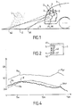
- a humidity detector D of the road R is planned to control the intensity of the light emission from the projectors Pr, Pl according to this state of humidity of the road and the shape of the road.
- the device D comprises an optical sensor 1 embedded in the vehicle and a means 2 for forming on the optical sensor 1 a image of an area Z of the road located in front of the vehicle.
- the optical sensor 1 is designed to work in the radiation visible. It is of a common type, inexpensive.
- the optical sensor 1 can consist of a CCD bar (charge transfer system) while the means 2 is formed by at least one lens.
- the optical sensor 1 is formed by the receiving plate 3 (Fig. 2) of a CCD camera 4 while the means 2 is formed by the objective of this camera.
- the receptor plate 3 is formed by a matrix of cells photosensitive constituting elementary points or pixels 5.
- the camera is oriented so that the area Z whose image is formed corresponds substantially to the area illuminated by the projector Pr, Pl in the "code" condition.
- Camera 4 could be of a different type, for example MOS camera type.
- the image taken into account, and analyzed for its light level relative, is that of at least one segment S (Fig.3) of the route oriented in the direction of progression F of the vehicle.
- the image of the segment S is formed along the vertical segment s of plate 3 (Fig. 2).
- the pixels of the plate 3 are scanned according to the columns as indicated by an arrow, i.e. in a vertical plane parallel to the direction of progression F.
- a point in segment S of the route R corresponds to a pixel of matrix 3 on image s.
- point B1 of segment S located closest to the vehicle corresponds to the pixel b1 end of segment s in Fig. 2.
- the lower pixel b2 of segment s in Fig. 2 corresponds to point B2 of the route.
- a relative light level provided by the corresponding pixel of the image s At every point on the route located at a different distance in front of the vehicle we can associate a relative light level provided by the corresponding pixel of the image s.
- the curve Rs corresponds to a dry road, for example bitumen dry
- the Rh curve corresponds to a wet road (wet bitumen) when the rain has stopped or is light
- the curve Rp corresponds to a road in heavy rain L.
- the curve Rs has an overall convexity turned towards the top, the maximum of the relative light level being obtained for points on the route located between 5 and 10 meters from the projector for the example considered.
- Rh curve for wet roads, begins above the curve Rs then crosses it at a point X corresponding to a point of the road located, for the example considered, at a distance of approximately 6 meters of the projector. The Rh curve then goes below the curve Rs. Beyond a distance of about 12 or 13 meters, the Rh curve presents a Rhr lift forming a bump whose top may slightly exceed the curve Rs.
- the Rp curve which corresponds to a road in heavy rain L (Fig. 1) is located clearly above the Rs and Rh curves. It has a convex part with a maximum located at a distance about 6 or 7 meters from the projector.
- the Rp curve shows a rise Rpr forming a bump for a distance from the projector substantially equal to that corresponding to the Rhr lift.
- the signal Rp returned to the cells photosensitive matrix 3 is the addition of the reflection on the ground and on the raindrops intercepted by the light beam from the projector. Signal amplitude and noise level are used to characterize this state.
- the level Rs is used as a reference.
- the device of the invention therefore makes it possible to clearly distinguish a wet road from a dry road by comparing Rh and Rs curves which have a cross point. It is also possible to distinguish the humidity of the road with intermediate curves not represented.
- the Rs, Rh, and Rp curves in Fig. 4 can be obtained by weighting of the values measured on several parallel segments S, S1, S2, etc ... of the road. Each of these road segments corresponds on the receiving plate 3 a segment s, s1, s2 located on a column of vertical scan. It is thus possible to determine a value average of the light level relative to a distance h from the projector vehicle by averaging the relative light levels of several route points located the same distance from this projector.
- FIG. 5 is a more detailed diagram of an exemplary embodiment.
- the camera 4 of the humidity detector device is housed in the Pr projector and its optics is thus protected against dirt.
- a cleaning device is generally provided for the optics of the projector, so that camera 4 benefits.
- the reflector 6 of the projector is systematically oriented in the right direction with respect to the ground thanks to a correction device automatic trim (not shown).
- Camera 4 is mounted so to follow the angular movements of the reflector 6.
- the lamp 7 is arranged in the center of the reflector 6.
- a smaller concave mirror 8 dimension that the reflector 6, is arranged in the concavity of the reflector 6.
- the mirror 8 has a central opening 9 for the engagement of the lamp 7.
- the mirror 8 is mounted mobile so as to modify the beam bright at several levels of definition, depending on the humidity state of the route that has been detected.
- the mirror 8 is mounted on a support 10 which can be moved in translation by an electric motor 11 acting on a screw 12.
- the support 10 can be slidably mounted according to the direction of the optical axis of the reflector 6 or pivoting around a point of articulation of a frame supporting the motor 11.
- the information provided by the camera 4 on the brightness level different points of the route are sent to a module signal processing electronics 13 which performs, in tables, comparison of the road level light level survey with the reference Rs (Fig. 4) stored in memory means.
- the reference curve Rs can be updated automatically or on the initiative of the driver when driving on a dry road.
- the electronic module 13 is a processing module of images, known in itself.
- the amount of information is important and allows fine discrimination of the humidity conditions of the road.
- the module 13 Depending on the discriminated humidity state, the module 13 sends on its output line 14 a command signal to the motor 11 to move the mobile mirror 8 of a determined amplitude in order to modify the level definition of the light beam according to the detected humidity state.
- a similar control is provided for the other projector P1.
- a standard camera 4 or of Cheap CCD optical sensors is particularly advantageous.
- the camera could be used for other purposes, for example automatic ignition headlights, fog detection. Integration of the system in the projector allows to benefit from self-cleaning generally provided for the optics of the projector, and provides mechanical protection of the device.
Landscapes
- Engineering & Computer Science (AREA)
- Mechanical Engineering (AREA)
- General Health & Medical Sciences (AREA)
- Chemical & Material Sciences (AREA)
- Analytical Chemistry (AREA)
- Biochemistry (AREA)
- Physics & Mathematics (AREA)
- General Physics & Mathematics (AREA)
- Immunology (AREA)
- Pathology (AREA)
- Life Sciences & Earth Sciences (AREA)
- Health & Medical Sciences (AREA)
- Investigating Or Analysing Materials By Optical Means (AREA)
- Lighting Device Outwards From Vehicle And Optical Signal (AREA)
- Closed-Circuit Television Systems (AREA)
Abstract
Description
- route légèrement humide,
- route très mouillée,
- un état intermédiaire entre les deux précédents,
- pluie.
Claims (11)
- Procédé pour détecter l'état d'humidité d'une route sur laquelle circule un véhicule automobile dans des conditions d'obscurité nécessitant la mise en service de l'éclairage du véhicule, selon lequel on prévoit un capteur optique (1) embarqué dans le véhicule, et on forme sur ce capteur optique une image d'une zone (Z) de la route située en avant du véhicule, caractérisé par le fait que la zone (Z) de la route prise en considération est formée par au moins un segment (S) orienté suivant le sens de progression (F) du véhicule de sorte que l'image considérée (s) est un profil en long (Rh, Rp) de la répartition lumineuse sur la route, que l'on compare cette image avec une référence (Rs) pour déterminer l'état d'humidité, et que la référence (Rs) correspond au profil en long de la répartition lumineuse d'au moins un segment équivalent de route sèche.
- Procédé selon la revendication 1, caractérisé par le fait que la longueur du segment de route (S) prise en compte est suffisante pour faire apparaítre un croisement (X) du profil en long de la répartition lumineuse sur route humide (Rh) et de la répartition lumineuse (Rs) sur route sèche.
- Procédé selon la revendication 1 ou 2, caractérisé par le fait que la longueur du segment de route (S) prise en compte est d'environ quinze mètres à partir du projecteur.
- Procédé selon l'une des revendications précédentes, caractérisé par le fait que l'image (s) de la zone de la route formée sur le capteur optique est balayée suivant une direction située dans un plan vertical parallèle au sens de progression du véhicule.
- Procédé selon l'une des revendications précédentes, caractérisé par le fait que la zone (Z) de la route prise en considération est formée par plusieurs segments parallèles (S, S1 S2,...) orientés suivant le sens de progression (F) du véhicule, qu'à chacun de ces segments de route correspond sur un segment image ( s, s1, s2,...) vertical, et qu'une valeur moyenne du niveau lumineux relatif à une distance (h) du projecteur du véhicule est déterminée en calculant la moyenne des niveaux lumineux relatifs de plusieurs points de la route situés à une même distance (h) de ce projecteur.
- Dispositif pour détecter l'état d'humidité d'une route sur laquelle circule un véhicule automobile, dans des conditions d'obscurité telles que l'éclairage du véhicule est mis en service, comprenant un capteur optique (1) embarqué dans le véhicule et un moyen (2) pour former sur le capteur optique une image d'une zone (Z) de la route située en avant du véhicule, caractérisé par le fait que le moyen (2) est propre à former une image d'au moins un segment (S) orienté suivant le sens de progression du véhicule, de sorte que l'image considérée (s) est un profil en long de la répartition lumineuse sur la route, qu'une référence (Rs) correspondant au profil en long d'au moins un segment équivalent de route sèche est stockée dans un moyen de mémoire et qu'un moyen de comparaison est prévu pour comparer l'image reçue par le capteur optique avec la référence.
- Dispositif selon la revendication 6, caractérisé par le fait que le capteur optique (1) est constitué par l'un des capteurs suivants : une barrette CCD, une barrette de photodiodes, une caméra CCD (4) ou MOS.
- Dispositif selon la revendication 7, caractérisé par le fait que les cellules photosensibles constituant les points élémentaires ou pixels (5) du capteur optique (1) sont balayés suivant une direction située dans un plan vertical parallèle au sens de progression (F).
- Dispositif selon l'une des revendication 6 à 8, caractérisé par le fait que le capteur optique (1) est formé par une caméra (4) ayant un champ angulaire suffisant, en particulier de l'ordre de 60°, pour qu'il ne soit pas nécessaire de régler l'orientation de la caméra par rapport au sol.
- Dispositif selon l'une des revendication 6 à 9, caractérisé par le fait que le capteur optique (1) est formé par une caméra (4) installée dans le projecteur (Pr) et soumise à la même correction automatique d'assiette que le projecteur, lequel est systématiquement orienté dans la direction correcte par rapport au sol par un dispositif de correction automatique.
- Dispositif selon l'une des revendication 6 à 10, caractérisé par le fait qu'il comporte un module électronique (13) de traitement d'images auquel sont envoyées les informations sur le niveau de luminosité des différents points de la route, le module électronique (13) effectuant la comparaison du relevé de niveaux lumineux des points de la route avec la référence (Rs) stockée dans des moyens de mémoire, et envoyant sur une ligne de sortie (14) un signal de commande pour modifier le niveau de définition du faisceau lumineux du projecteur selon l'état d'humidité détecté.
Applications Claiming Priority (2)
| Application Number | Priority Date | Filing Date | Title |
|---|---|---|---|
| FR0108903 | 2001-06-29 | ||
| FR0108903A FR2826727B1 (fr) | 2001-06-29 | 2001-06-29 | Procede et dispositif pour detecter l'etat d'humidite d'une route sur laquelle circule un vehicule |
Publications (1)
| Publication Number | Publication Date |
|---|---|
| EP1273476A1 true EP1273476A1 (fr) | 2003-01-08 |
Family
ID=8865144
Family Applications (1)
| Application Number | Title | Priority Date | Filing Date |
|---|---|---|---|
| EP02291564A Withdrawn EP1273476A1 (fr) | 2001-06-29 | 2002-06-24 | Procédé et dispositif pour détecter l'état d'humidité d'une route sur laquelle circule un véhicule |
Country Status (4)
| Country | Link |
|---|---|
| US (1) | US6765353B2 (fr) |
| EP (1) | EP1273476A1 (fr) |
| JP (1) | JP2003121345A (fr) |
| FR (1) | FR2826727B1 (fr) |
Families Citing this family (42)
| Publication number | Priority date | Publication date | Assignee | Title |
|---|---|---|---|---|
| DE10310698A1 (de) * | 2003-03-12 | 2004-09-23 | Valeo Schalter Und Sensoren Gmbh | Optisches Erfassungssystem für Kraftfahrzeuge |
| JP4258385B2 (ja) * | 2004-01-14 | 2009-04-30 | 株式会社デンソー | 路面反射検出装置 |
| US20060095172A1 (en) * | 2004-10-28 | 2006-05-04 | Abramovitch Daniel Y | Optical navigation system for vehicles |
| FR2885860B1 (fr) * | 2005-05-20 | 2007-08-17 | Valeo Vision Sa | Dispositif de detection d'obstacles comportant un systeme d'imagerie pour vehicule automobile |
| DE102005043058A1 (de) * | 2005-08-24 | 2007-03-01 | Plöchinger, Heinz, Dipl.-Ing. | Fahrzeugleuchte mit integriertem Sensor |
| FR2902556B1 (fr) * | 2006-06-15 | 2008-08-15 | Valeo Vision Sa | Procede de determination d'une distance de visibilite pour un conducteur d'un vehicule. |
| JP2009053818A (ja) * | 2007-08-24 | 2009-03-12 | Toshiba Corp | 画像処理装置及びその方法 |
| JP5029508B2 (ja) * | 2008-06-19 | 2012-09-19 | トヨタ自動車株式会社 | 車両用撮像照明装置 |
| EP2196792B1 (fr) * | 2008-12-09 | 2011-04-06 | C.R.F. Società Consortile per Azioni | Dispositif optique pour véhicules à moteur, pour détecter l'état de la surface routière |
| JP5546326B2 (ja) * | 2010-04-12 | 2014-07-09 | 株式会社小糸製作所 | 制御装置、車両用灯具システム、車両用灯具 |
| DE102010023856A1 (de) * | 2010-06-15 | 2011-12-22 | Wabco Gmbh | Sensor zur berührungslosen Bestimmung der Fahrbahnbeschaffenheit und dessen Verwendung |
| DE102010044263A1 (de) * | 2010-09-03 | 2012-03-08 | Daimler Ag | Vorrichtung und Verfahren zur Steuerung eines aktiven Fahrwerks eines Fahrzeugs |
| DE102011017697A1 (de) * | 2011-04-28 | 2012-10-31 | Robert Bosch Gmbh | Verfahren zur Leuchtweitenregulierung zumindest eines Scheinwerfers eines Fahrzeugs und Lichtsteuergerät |
| EP2721554A2 (fr) * | 2011-06-17 | 2014-04-23 | Robert Bosch GmbH | Procédé et appareil de commande permettant de détecter une condition météorologique dans un environnement d'un véhicule |
| JP5803330B2 (ja) * | 2011-06-27 | 2015-11-04 | アイシン精機株式会社 | 車両周辺撮影装置 |
| DE102012007908B4 (de) * | 2012-04-23 | 2014-10-16 | Audi Ag | Verfahren und Scheinwerferanlage zum Ausgleich von Ausrichtfehlern eines Scheinwerfers |
| JP5980568B2 (ja) * | 2012-05-18 | 2016-08-31 | 株式会社小糸製作所 | 車両用灯具 |
| US20140247349A1 (en) * | 2013-03-04 | 2014-09-04 | GM Global Technology Operations LLC | Integrated lighting, camera and sensor unit |
| US9126534B2 (en) * | 2013-03-14 | 2015-09-08 | Ford Global Technologies, Llc | Automated camera wash for vehicles |
| CA2941270A1 (fr) * | 2014-03-03 | 2015-09-11 | G. Lufft Mess- Und Regeltechnik Gmbh | Projecteur de vehicule comportant un dispositif pour determiner des conditions de la route et systeme pour surveiller des conditions de la route |
| US20150363654A1 (en) * | 2014-06-12 | 2015-12-17 | GM Global Technology Operations LLC | Vision-based wet road surface detection using mirrored and real images |
| DE102014224857A1 (de) * | 2014-12-04 | 2016-06-09 | Conti Temic Microelectronic Gmbh | Sensorsystem und Verfahren zur Klassifikation von Fahrbahnoberflächen |
| US9616773B2 (en) | 2015-05-11 | 2017-04-11 | Uber Technologies, Inc. | Detecting objects within a vehicle in connection with a service |
| JP6582055B2 (ja) * | 2015-10-22 | 2019-09-25 | 京セラ株式会社 | 路面状態判定装置、撮像装置、撮像システムおよび路面状態判定方法 |
| US20170168495A1 (en) * | 2015-12-10 | 2017-06-15 | Uber Technologies, Inc. | Active light sensors for determining expected traction value of a road segment |
| US10712160B2 (en) | 2015-12-10 | 2020-07-14 | Uatc, Llc | Vehicle traction map for autonomous vehicles |
| US9840256B1 (en) | 2015-12-16 | 2017-12-12 | Uber Technologies, Inc. | Predictive sensor array configuration system for an autonomous vehicle |
| US9841763B1 (en) | 2015-12-16 | 2017-12-12 | Uber Technologies, Inc. | Predictive sensor array configuration system for an autonomous vehicle |
| US9990548B2 (en) | 2016-03-09 | 2018-06-05 | Uber Technologies, Inc. | Traffic signal analysis system |
| US10459087B2 (en) | 2016-04-26 | 2019-10-29 | Uber Technologies, Inc. | Road registration differential GPS |
| US9672446B1 (en) | 2016-05-06 | 2017-06-06 | Uber Technologies, Inc. | Object detection for an autonomous vehicle |
| US10678262B2 (en) | 2016-07-01 | 2020-06-09 | Uatc, Llc | Autonomous vehicle localization using image analysis and manipulation |
| US10197486B2 (en) * | 2017-04-30 | 2019-02-05 | Behrouz Mataei | Pavement drainage evaluation system |
| US11334753B2 (en) | 2018-04-30 | 2022-05-17 | Uatc, Llc | Traffic signal state classification for autonomous vehicles |
| CN111491416B (zh) * | 2019-01-25 | 2022-04-19 | 光宝电子(广州)有限公司 | 照明设备及其控制方法 |
| CN113632412A (zh) * | 2019-03-26 | 2021-11-09 | 株式会社小糸制作所 | 汽车及车辆用灯具 |
| FI128495B (en) * | 2019-05-21 | 2020-06-15 | Vaisala Oyj | Method for calibrating optical surface monitoring system, arrangement, device and computer readable memory |
| DE102020133935A1 (de) * | 2020-12-17 | 2022-06-23 | Dr. Ing. H.C. F. Porsche Aktiengesellschaft | Batteriegehäuse zum Aufnehmen einer Hochvoltbatterie, insbesondere einer Hochvoltbatterie eines Kraftfahrzeugs, Kraftfahrzeug, Verfahren zum Überprüfen einer in einem Batteriegehäuse angeordneten Hochvoltbatterie |
| EP4199493B1 (fr) * | 2021-12-15 | 2025-06-04 | ZKW Group GmbH | Système de phares de véhicule |
| DE102022107333A1 (de) | 2022-03-29 | 2023-10-05 | HELLA GmbH & Co. KGaA | Vorrichtung und Verfahren zur Erfassung eines Niederschlags |
| CN115657766B (zh) * | 2022-09-28 | 2026-01-16 | 浙江卡罗莱纳纺织有限公司 | 一种带目标检测的纱线温湿度调节装置 |
| KR102807976B1 (ko) * | 2023-03-31 | 2025-05-19 | 한국광기술원 | 노면의 마찰 상태 분석이 가능한 차량용 램프 |
Citations (6)
| Publication number | Priority date | Publication date | Assignee | Title |
|---|---|---|---|---|
| DE4133359A1 (de) * | 1991-10-09 | 1993-04-15 | Porsche Ag | Verfahren und vorrichtung zur beruehrungslosen erfassung der dicke einer wasserschicht auf einer fahrbahn |
| FR2707390A1 (fr) * | 1993-07-09 | 1995-01-13 | Valeo Vision | Dispositif indicateur d'assiette pour véhicule automobile. |
| EP0642950A1 (fr) * | 1993-09-15 | 1995-03-15 | Valeo Vision | Dispositif de commande automatique de l'orientation des projecteurs d'un véhicule automobile en fonction des variations d'assiette de celui-ci |
| DE19645625A1 (de) * | 1996-11-06 | 1998-05-07 | Bosch Gmbh Robert | Scheinwerferanlage für Fahrzeuge |
| DE19730414A1 (de) * | 1997-07-16 | 1999-01-21 | Opel Adam Ag | Verfahren und Vorrichtung zur vorausschauenden Fahrbahnbeurteilung |
| DE19854964A1 (de) * | 1998-11-29 | 2000-06-08 | Martin Spies | Sensor zur Fahrbahnbeurteilung |
Family Cites Families (3)
| Publication number | Priority date | Publication date | Assignee | Title |
|---|---|---|---|---|
| FR2721400B1 (fr) | 1994-06-16 | 1996-09-13 | Valeo Vision | Procédé et dispositif de détection de brouillard ou de fumée, notamment pour véhicule automobile. |
| US6049171A (en) * | 1998-09-18 | 2000-04-11 | Gentex Corporation | Continuously variable headlamp control |
| JPH11321440A (ja) * | 1998-05-18 | 1999-11-24 | Koito Mfg Co Ltd | 車輌用灯具装置 |
-
2001
- 2001-06-29 FR FR0108903A patent/FR2826727B1/fr not_active Expired - Fee Related
-
2002
- 2002-06-24 EP EP02291564A patent/EP1273476A1/fr not_active Withdrawn
- 2002-06-25 US US10/183,310 patent/US6765353B2/en not_active Expired - Fee Related
- 2002-06-28 JP JP2002190282A patent/JP2003121345A/ja active Pending
Patent Citations (6)
| Publication number | Priority date | Publication date | Assignee | Title |
|---|---|---|---|---|
| DE4133359A1 (de) * | 1991-10-09 | 1993-04-15 | Porsche Ag | Verfahren und vorrichtung zur beruehrungslosen erfassung der dicke einer wasserschicht auf einer fahrbahn |
| FR2707390A1 (fr) * | 1993-07-09 | 1995-01-13 | Valeo Vision | Dispositif indicateur d'assiette pour véhicule automobile. |
| EP0642950A1 (fr) * | 1993-09-15 | 1995-03-15 | Valeo Vision | Dispositif de commande automatique de l'orientation des projecteurs d'un véhicule automobile en fonction des variations d'assiette de celui-ci |
| DE19645625A1 (de) * | 1996-11-06 | 1998-05-07 | Bosch Gmbh Robert | Scheinwerferanlage für Fahrzeuge |
| DE19730414A1 (de) * | 1997-07-16 | 1999-01-21 | Opel Adam Ag | Verfahren und Vorrichtung zur vorausschauenden Fahrbahnbeurteilung |
| DE19854964A1 (de) * | 1998-11-29 | 2000-06-08 | Martin Spies | Sensor zur Fahrbahnbeurteilung |
Also Published As
| Publication number | Publication date |
|---|---|
| FR2826727A1 (fr) | 2003-01-03 |
| US20030001509A1 (en) | 2003-01-02 |
| JP2003121345A (ja) | 2003-04-23 |
| US6765353B2 (en) | 2004-07-20 |
| FR2826727B1 (fr) | 2004-05-28 |
Similar Documents
| Publication | Publication Date | Title |
|---|---|---|
| FR2826727A1 (fr) | Procede et dispositif pour detecter l'etat d'humidite d'une route sur laquelle circule un vehicule | |
| KR100504598B1 (ko) | 수분센서와 방풍유리의 안개 검출기 | |
| JP4053498B2 (ja) | 湿度センサ及びフロントガラス曇り検出器 | |
| JP3970843B2 (ja) | イメージ・センサによるステレオイメージ形成を利用した湿気センサ | |
| US6207967B1 (en) | Off the glass imaging rain sensor | |
| US7019275B2 (en) | Moisture sensor and windshield fog detector | |
| EP0685733B1 (fr) | Procédé de mesure de la qualité optique d'un vitrage | |
| EP3792619B1 (fr) | Ensemble de détection de défauts sur une carrosserie d'un véhicule automobile | |
| FR2652317A1 (fr) | Dispositif d'eclairage pour vehicules notamment pour permettre une zone de vision etendue en position de croissement. | |
| FR2923016A1 (fr) | Procede de detection d'un phenomene perturbateur de visibilite pour un vehicule. | |
| FR2787864A1 (fr) | Projecteur permettant une attenuation de l'eclairage de la zone proche a l'avant du vehicule | |
| FR2967107A1 (fr) | Montage de camera et son procede pour un vehicule automobile | |
| FR2466767A1 (fr) | Procede pour tester la qualite de l'ensemble constitue par un balai d'essuie-glace et la surface de la glace | |
| US6429933B1 (en) | Method of image processing for off the glass rain sensing | |
| FR2710014A1 (fr) | Dispositif de commande automatique de l'orientation des projecteurs d'un véhicule automobile en fonction des variation d'assiette de celui-ci. | |
| FR2730201A1 (fr) | Dispositif pour la correction automatique de l'orientation d'au moins un projecteur de vehicule lors des variations d'assiettes de celui-ci | |
| FR2847367A1 (fr) | Procede et dispositif de determination de la distance de visibilite du conducteur d'un vehicule | |
| FR2859860A1 (fr) | Dispositif de detection d'obstacle comportant un systeme d'imagerie stereoscopique incluant deux capteurs optiques | |
| EP1580074B1 (fr) | Procédé de détection d'une route mouillée et système d'éclairage mettant en oeuvre ce procédé | |
| EP4251473A1 (fr) | Procédé de contrôle d'un système d'éclairage mettant en oeuvre une fonction d'éclairage non éblouissant | |
| EP1713132B1 (fr) | Capteur photosensible et ses applications dans le domaine automobile | |
| FR2817964A1 (fr) | Dispositif d'inspection automatique de surface d'une bande en defilement | |
| FR2945130A1 (fr) | Organe guide de lumiere et capteur optique equipe d'un tel guide de lumiere | |
| FR2939194A1 (fr) | Capteur de luminosite, notamment pour vehicule automobile | |
| FR2745655A1 (fr) | Dispositif de detection de mobiles |
Legal Events
| Date | Code | Title | Description |
|---|---|---|---|
| PUAI | Public reference made under article 153(3) epc to a published international application that has entered the european phase |
Free format text: ORIGINAL CODE: 0009012 |
|
| AK | Designated contracting states |
Kind code of ref document: A1 Designated state(s): AT BE CH CY DE DK ES FI FR GB GR IE IT LI LU MC NL PT SE TR |
|
| AX | Request for extension of the european patent |
Free format text: AL;LT;LV;MK;RO;SI |
|
| 17P | Request for examination filed |
Effective date: 20030120 |
|
| AKX | Designation fees paid |
Designated state(s): AT BE CH CY DE DK ES FI FR GB GR IE IT LI LU MC NL PT SE TR |
|
| 17Q | First examination report despatched |
Effective date: 20090423 |
|
| STAA | Information on the status of an ep patent application or granted ep patent |
Free format text: STATUS: THE APPLICATION IS DEEMED TO BE WITHDRAWN |
|
| 18D | Application deemed to be withdrawn |
Effective date: 20140103 |