EP1271741A2 - Système pour la stabilisation d'un réseau d'alimentation en puissance - Google Patents
Système pour la stabilisation d'un réseau d'alimentation en puissance Download PDFInfo
- Publication number
- EP1271741A2 EP1271741A2 EP02014398A EP02014398A EP1271741A2 EP 1271741 A2 EP1271741 A2 EP 1271741A2 EP 02014398 A EP02014398 A EP 02014398A EP 02014398 A EP02014398 A EP 02014398A EP 1271741 A2 EP1271741 A2 EP 1271741A2
- Authority
- EP
- European Patent Office
- Prior art keywords
- converter
- power supply
- supply network
- power
- machine
- Prior art date
- Legal status (The legal status is an assumption and is not a legal conclusion. Google has not performed a legal analysis and makes no representation as to the accuracy of the status listed.)
- Withdrawn
Links
Images


Classifications
-
- B—PERFORMING OPERATIONS; TRANSPORTING
- B30—PRESSES
- B30B—PRESSES IN GENERAL
- B30B15/00—Details of, or accessories for, presses; Auxiliary measures in connection with pressing
- B30B15/14—Control arrangements for mechanically-driven presses
- B30B15/148—Electrical control arrangements
-
- H—ELECTRICITY
- H02—GENERATION; CONVERSION OR DISTRIBUTION OF ELECTRIC POWER
- H02J—CIRCUIT ARRANGEMENTS OR SYSTEMS FOR SUPPLYING OR DISTRIBUTING ELECTRIC POWER; SYSTEMS FOR STORING ELECTRIC ENERGY
- H02J3/00—Circuit arrangements for ac mains or ac distribution networks
- H02J3/28—Arrangements for balancing of the load in a network by storage of energy
- H02J3/30—Arrangements for balancing of the load in a network by storage of energy using dynamo-electric machines coupled to flywheels
-
- H—ELECTRICITY
- H02—GENERATION; CONVERSION OR DISTRIBUTION OF ELECTRIC POWER
- H02K—DYNAMO-ELECTRIC MACHINES
- H02K7/00—Arrangements for handling mechanical energy structurally associated with dynamo-electric machines, e.g. structural association with mechanical driving motors or auxiliary dynamo-electric machines
- H02K7/02—Additional mass for increasing inertia, e.g. flywheels
- H02K7/025—Additional mass for increasing inertia, e.g. flywheels for power storage
-
- Y—GENERAL TAGGING OF NEW TECHNOLOGICAL DEVELOPMENTS; GENERAL TAGGING OF CROSS-SECTIONAL TECHNOLOGIES SPANNING OVER SEVERAL SECTIONS OF THE IPC; TECHNICAL SUBJECTS COVERED BY FORMER USPC CROSS-REFERENCE ART COLLECTIONS [XRACs] AND DIGESTS
- Y02—TECHNOLOGIES OR APPLICATIONS FOR MITIGATION OR ADAPTATION AGAINST CLIMATE CHANGE
- Y02E—REDUCTION OF GREENHOUSE GAS [GHG] EMISSIONS, RELATED TO ENERGY GENERATION, TRANSMISSION OR DISTRIBUTION
- Y02E60/00—Enabling technologies; Technologies with a potential or indirect contribution to GHG emissions mitigation
- Y02E60/16—Mechanical energy storage, e.g. flywheels or pressurised fluids
Definitions
- the invention relates to a stabilization system for a through a power supply network fed power supply network, comprising a to the power supply network connected converter system with a flywheel accumulator.
- Such a stabilization system is known from DE 20 41 924, wherein it is designed to compensate for deficits in the electricity grid.
- the invention is therefore based on the object of a system for stabilization to create a power supply network that is able to Stabilize voltage in the power supply network to a certain value.
- the system according to the invention has the advantage that it is able to to take up power from the power supply network as well surrendering this and thus any kind of fluctuations in performance in the power supply network balance and the voltage with respect to rms value and Stabilize phase position completely.
- the converter system is a converter machine with which the power supply network not only Active power can be supplied or removed, but also reactive power can be supplied or removed to the voltage in the power supply network to keep essentially constant.
- a particularly advantageous embodiment of the solution according to the invention provides a choke which connects the power supply network with the power supply network combines.
- a particularly expedient solution provides that the counter-reactance the coupling choke approximately the subtransient reactance of the converter machine equivalent. In this case there is an optimal adjustment between Converter and coupling choke reached, so that the coupling choke Effect of the converter machine for stabilizing the power supply network optimally supported.
- a particularly advantageous embodiment of the stabilization system according to the invention provides that the converter system is a converter system with which the flywheel storage so with the converter machine can be coupled that the flywheel storage power from the converter machine can record or give to these.
- the converter system can be designed as long as it is a quick and reliable change between power consumption and Power output of the flywheel storage enables.
- a special one favorable solution provides that the converter system at least one Converter circuit with two coupled via a DC link Includes inverters. Such a converter system is easy to operate and also allows the possibility of controlling the power taken up or given off by the flywheel storage the accuracy required for good stabilization, to regulate.
- each of the converters between a rectifier function and an inverter function is reversible. So that is both the power consumption and the power output of the flywheel storage easily controllable.
- the inverters can only be controlled by a controller that in a converter circuit one of the converters in the rectifier function and the another works in inverter function. This means that it is always ready for operation of the converter circuit, either for power consumption or for the performance.
- the converter system comprises several converter circuits connected in parallel. That would be with this solution
- the converter circuit should be designed so that it is only used to output the flywheel storage can be used and to train the other converter circuit so that it can only be used for power consumption of the flywheel storage.
- each of the converter circuits of the Converter system is provided with reversible converters, for example the possibility is created to set up a redundant system, that, for example, still works even if one converter circuit fails.
- Another advantageous solution provides that the converter of a converter circuit preferred by the controller for power output to the converter machine or power consumption from the converter machine can be used are.
- this preferred applicability excludes reversibility of the Inverters in the inverter circuits are not off. So the reversibility for that Maintaining redundancy of the system can be used advantageously.
- a choke is arranged in each converter circuit.
- Such a choke has the advantage that with this current changes due to differences in Instantaneous voltage values caused by switching or reversing the Both inverters are conditional, can be minimized.
- An advantageous embodiment of a controller according to the invention provides that the controller controls the voltage in the grid and the Voltage in the power supply network is recorded and compared. So that's it Control able to even the voltage and phase difference between the power supply network and the power feed-in network and the power coupling caused by the converter system between the To control the flywheel storage and the converter machine precisely, this in particular by specifying an ignition angle for the converter.
- a particularly favorable structure of the controller provides that it is still additionally the current in the DC link of the respective converter circuit for control purposes.
- the excitation winding is brushless excitable.
- This control of the excitation of the converter machine is preferably independent from the controller for the converter system, so that regardless of independent control of the converter machine when the converter system is working, in particular even in the form of a regulation.
- An advantageous exemplary embodiment provides that the converter machine has a single three-phase winding, which is connected to the power supply network and to the converter system. This is the easiest way to build such a converting machine, which, however, in terms of the quality of those in the power grid applied voltage has disadvantages, especially since this with Peaks and dips due to the switching of the converter system is.
- a further advantageous solution provides that the converter machine has a first and a second three-phase winding, so that in each case the power supply network with a three-phase winding and the Flywheel storage can be coupled to the other three-phase winding.
- first three-phase winding and the second three-phase winding have the same number of poles.
- a particular advantage of two three-phase windings is independent of that Question of the applied voltage, but especially to be seen in the fact that thereby a galvanic decoupling of the power supply network and the Converter system with the flywheel storage is possible.
- a particularly favorable solution provides that the first three-phase winding and the second three-phase winding is arranged in separate slots are.
- the rotor has a damper winding.
- Damper winding has the advantage that it harmonics of the adjacent Effectively short-circuits and thus eliminated in the river, so that only the fundamental frequency from one three-phase winding to the other three-phase winding is transmitted.
- the flywheel is suspended, that is, the flywheel towards it
- the bearing supporting the axis of rotation lies vertically above the flywheel Storage of the flywheel can also at high speeds Simply stabilize the flywheel.
- the bearing can stabilize the flywheel in the axial direction be designed as a plain bearing.
- this bearing is designed as a magnetic bearing, which has the advantage that lower bearing friction forces occur.
- a particularly inexpensive solution, especially with regard to selection security provides that the magnetic bearing is designed as a passive magnetic bearing is.
- flywheel is on a Magnetic bearing is arranged opposite side of the rotor, so that both the rotor and the flywheel are suspended relative to the magnetic bearing are arranged and thus a simple stabilization also with regard to Tipping moments is available.
- the synchronous machine is preferably associated with one of these Excitation machine provided, which also offers the possibility of To control the excitation of the synchronous machine and thus also from it to control the power taken or supplied to it exactly.
- the system according to the invention can also be designed in this way be that the converter system in the event of a power supply failure by the Power supply network the total consumed in the power supply network Delivers power, which means that in this case the converter system still at the same time as an uninterruptible power supply for the power supply network available at least in a certain time interval stands. In this case, it is necessary to use the flywheel storage dimension the load permitted in the power supply network.
- the system according to the invention thus not only provides constant stabilization the voltage in the power supply network if it works Electricity grid, but is also able to self-failure To bridge the electricity grid for a certain period of time.
- the system according to the invention can also be expanded so that the converter machine of the converter system with a motor drive, for example a diesel engine can be coupled, which is then driven by the rotor of the converter machine this operates as a generator, which is the voltage for the power supply network supplies.
- the converter system is still used here still to stabilize the voltage in the power grid, in particular the converter system and the flywheel storage in the On the one hand, they are able to compensate for load changes in the power supply network or on the other hand also power fluctuations of the converter machine balance driving motor.
- a first embodiment of a stabilization system according to the invention a power supply network 10, which by means of a choke 12 connected to a power feed network 14 includes one as a whole with 20 designated converter system, which has a converter machine 22.
- the converter machine 22 in turn has a first three-phase winding 24 and a second three-phase winding 26, and a rotor 28, which with an excitation winding 30 is provided.
- the field winding 30 is preferably expanded as a DC winding, which via an excitation machine 32 can be excited with a stationary DC winding 34.
- the second three-phase winding 26 is designated 40 as a whole Converter system connected, for example a converter circuit 42 includes one connected to the second three-phase winding 26 Converter 44 and a converter 46 is provided, both Inverters 44, 46 are coupled via a DC intermediate circuit 48. In a choke 49 is also provided to the direct current circuit 48.
- the choke 49 in the DC circuit 40 is used for current changes and thus differences in the instantaneous voltage values due to the Switch the two inverters to compensate.
- the converter 46 is in turn labeled 50 as a whole Flywheel memory provided which a synchronous machine 52 and with this has a coupled flywheel 54.
- the synchronous machine 52 comprises a stationary three-phase winding 56 and a rotor 58 with an excitation winding 60, which over a Exciter machine 62 can be brushed with direct current.
- the Exciter machine 62 includes a stationary DC winding 64 for Control of the excitation current in the excitation winding 60.
- An excitation control 66 is used to apply the DC winding 64 provided, which on the one hand can be predetermined by a setpoint generator 68 Compares the voltage setpoint with the voltage on the three-phase winding 56, which can be detected by a voltage detector 70.
- the converter system 40 is in turn labeled 80 as a whole Controllable, which has a frequency controller 82, the the voltage of the power supply network 10 and the voltage of the power supply network 14 detects and compares and also a downstream of this Current regulator 84 which is a current in the DC link 48 detected in addition to the output signal of the frequency controller 82 and in turn Activation controls 86 and 88 controls for the converter 44 and 46.
- the ignition devices 86 and 88 can each be determined that one of the converters 44 or 46 as a rectifier and the other converter 46 or 44 as Inverter works and is also via the ignition devices 86 and 88 Another ignition angle can be specified for both inverters.
- the system according to the invention now works in such a way that that of the power supply network 14 power supply network fed via the chokes 12 is stabilized in that the converter system 20 from the power supply network 10 either takes power or supplies power to it, each depending on the direction in which there is a change in the stabilization Voltage of the power supply network 10 results. For example, if the Current supply network 14 voltage supplied lower, leads the converter system 20 the power grid 10 power to the To keep voltage in the power supply network 10 constant. At the same time also supplied power when, for example, in the power supply network 10 a load is applied or, for example, an energy generator is switched off in the power supply network 10.
- the power supply network 10 power taken, if, for example, a load shedding or an activation of an energy generator takes place, which would lead to that the voltage in the power supply network 10 above the desired Tension would increase.
- the power withdrawal and power supply via the converter system 20 takes place on the one hand by controlling the generated by the converter machine 22 Voltage in that the voltage regulator 36 the voltage in Power supply network 10 detected and with that specified in the setpoint generator 38 Compare setpoint. Accordingly, the Excitation in the field winding 30 in the rotor 28.
- the frequency regulator 82 detects the voltage in the power supply network 10 and the voltage in the grid 14 and the current in DC link 48 and controls the ignition devices accordingly 86 and 88 of the converter 44 and 46 so that the converter circuit 42 due of the converter 44 connected to the second three-phase winding 26 Active power via the converter machine 22 from the power supply network 10 removes and via the synchronous machine 52 in the flywheel 54th stores, that is, the flywheel 54 accelerates to a higher speed, or so that the converter circuit 42 from the flywheel memory 50 by braking the flywheel 54 by means of the synchronous machine 52 Real power is drawn and via the converter machine 22 from the power supply network 10 feeds.
- flywheel accumulator 50 Due to the fact that the flywheel accumulator 50 has a high resistance to alternating loads has the possibility, also within very short cycles of active power from the power supply network 10 or feed it.
- Converter 22 With each type of stabilization of the power supply network 10 leads Converter 22 the power supply network 10 not only real power increases or removes this from this, but also leads to reactive power or take them out of them so that there is a possibility of large ones Voltage fluctuations, preferably voltage fluctuations of up to 50% to compensate for a relatively low withdrawal or supply of active power, since the converter machine 22 is capable of in addition to the active power to supply very high reactive powers to the power supply network 10 or to be taken from these, then to that of the power supply network 14 add voltage still supplied so that in the power supply network 10 the voltage is kept substantially constant.
- Voltage fluctuations preferably voltage fluctuations of up to 50% to compensate for a relatively low withdrawal or supply of active power
- a switch 16 is provided, which in the event of a breakdown of the voltage of the electricity grid is opened. This can be used, for Short circuit in the electricity grid an unnecessary power consumption by the Short circuit can be avoided.
- flywheel memory 50 that the flywheel 54 itself is arranged in a hanging manner, namely in one designated as a whole by 100 passive magnetic bearing, which is preferably in one piece with the Flywheel 54 connected flywheel shaft 102 in the direction of its axis 104 suspended, in addition, the flywheel shaft 102 in the magnetic bearing 100 adjacent radial bearings 106 and at a lower end of the flywheel shaft 102 arranged radial bearings 108 is mounted, the radial bearing 106 and 108 are preferably mechanical bearings that are only small Are exposed to loads.
- the flywheel is seated 54 near a lower end of the flywheel shaft 102, which in the Radial bearing 108 is mounted. Furthermore, the flywheel 54 is in the friction reducing gas atmosphere, preferably stored at negative pressure.
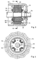
- a preferred embodiment of a conversion machine according to the invention, 3 and 4 comprises a housing 120 with end shields 122, in which a shaft 124 is rotatably mounted.
- the shaft 124 carries the rotor 28 with the field winding 30.
- a stand package designated as a whole by 126 arranged, in which, as shown in Fig. 4, both the first three-phase winding 24 and the second three-phase winding 26 are wrapped in such a way that the first three-phase winding 24 and the second three-phase winding 26 are identical and each relative to a groove pitch are offset from each other in the stand package 126.
- the winding strands of the first three-phase winding 24 are in Fig. 4 with solid lines 4, while the winding phases of the three-phase winding 26 in FIG. 4 are shown in dashed lines.
- the three-phase windings 24 and 26 are 4 in a machine in four-pole three-phase version with a shortened winding step of 5/6 pole pitch and for reasons of simplicity represented in the form of a single-layer winding.
- the rotor 28 is still with damping windings in the form of damper rods 128 provided, which in the area of the front ends of the rotor 28 are short-circuited by short-circuit plates 130.
- damper windings in rotor 28 are all harmonics on the first Three-phase winding 24 applied voltage effectively short-circuited and thus eliminated in the river. So there is the possibility of only the basic frequency from the first three-phase winding 24 to the second three-phase winding 26 to transmit.
- the rotating magnetic field of the first three-phase winding is created by the rotor 28 22 taken along, in the case of a synchronous machine trained converter machine, the carriage of the rotor takes place synchronously. Furthermore, no conversion of the first occurs in the converter machine 22 Three-phase winding 24 supplied power in mechanical energy. It rather there is a direct transformer transmission of the electrical Energy through flux linkage between the two three-phase windings 24 and 26.
- the converter machine is preferably designed in accordance with added powers of the first and second three-phase windings 24 and 26, which means twice the power for that of a known single-casing machine to design the same power for each engine and generator are. This leads to a significant reduction in the weight to performance ratio and also an increase in efficiency.
- the voltage regulator 36 ensures that the magnetic flux of the converter machine over the DC excitation of the rotor 28 takes place so that the voltage in the first Three-phase winding 24 remains essentially constant.
- the throttle 12 ' is not designed as a simple throttle, but rather as a coupling choke with a power supply network 14 facing first winding 12a ′, one of the power supply network 10 facing second winding 12b 'and an intermediate tap 12c', which with the first three-phase winding 24 of the converter machine 22 of the converter system 20 is connected.
- Such coupling throttle 12 ' has the Advantage that with this also short circuits in the power grid 14 through the Converter system 20 are controllable and the possibility is opened also by means of the converter system 20 in the power supply network 10 such short circuits to keep the voltage substantially constant.
- the second exemplary embodiment according to FIG. 5 is the first Embodiment identical, so that in this regard the content of the explanations can be referred to the first embodiment.
- the converter system 40 comprises two in parallel mutually arranged converter circuits 42a and 42b, each of the Converter circuits has a converter 44a, 44b, which with the second Three-phase winding 26 is connected and an inverter 46a, 46b, which with the three-phase winding 56 of the synchronous machine 52 of the flywheel memory 50 is connected. Furthermore, 42a and 42b, the two converters 44a, 46a and 44b, 46b via a DC link 48a and 48b coupled together.
- the controller 80 is designed so that it is able to Ignition devices 86a, 88a and 86b, 88b in the two converter circuits 42a, b to control.
- the two converter circuits 42a, 42b are preferably designed such that they are able to increase approximately half the maximum possible active power turn.
- converter circuit 42a is from controller 80 primarily operated so that this for coupling active power from the Converter machine for flywheel storage 50 can be used during the Converter circuit 42b is primarily operated so that it for coupling Active power from the flywheel storage 50 to the converter machine 22 can be used is. This is sufficient, as long as a maximum of half of each maximum possible active power between the converter machine 22 and the Flywheel accumulator 52 is to be switched.
- converter circuit 42a or 42b which in its basic setting is in the opposite Direction works, reversed by the controller 80, so that in In this case, both converter circuits 42a, 42b work in parallel.
- the reversibility of the converters 44a, b, 46a, b also has the advantage that a redundant system is available up to half the active power, since if one of the converter circuits 42a, 42b fails, the other converter circuit 42b, 42a by reversing the converter between the rectifier function and Inverter function for transferring active power in both directions can be used.
- the converter machine 22 ' is in the form of two separate ones Synchronous machines 22a 'and 22b' formed, each of these synchronous machines has an excitation winding 30a or, 30b and each excitation winding via a voltage regulator 36a or 36b provided for this purpose is adjustable.
- the voltage regulator 36b regulation takes place accordingly the voltage occurring in the second three-phase winding 26.
- the converter machine 22 in the form of a simplified machine and has only the three-phase winding 24, both with the intermediate tap 12c 'of the coupling choke 12' is also connected to the converter 44 of the Converter circuit 42 so that the second three-phase winding 26 can be omitted and is simultaneously formed by the first three-phase winding 24.
- the system according to the invention for stabilizing the voltage in the Power supply network 10 can preferably also be used to to work as an uninterruptible power supply.
- the Flywheel memory 50 dimensioned so that its energy is sufficient to the voltage in the voltage supply network 10 in the event of a failure of the Power feed network 14 upright for a period of up to 10 seconds to obtain. Since 97% of all common network failures in the electricity grid in If there are periods that are shorter than 10 seconds, the energy in the Flywheel storage 50 for 97% of all power grid 14 failures.
- an additional one Control can be provided, which for switching off the power supply network serves.
- the converter system 40 with the flywheel memory 50 continues to serve in the manner already described above to the tension in the Stabilize the power supply network, for example in the event of load jumps in the Power supply network and to support the diesel unit.
Applications Claiming Priority (3)
| Application Number | Priority Date | Filing Date | Title |
|---|---|---|---|
| DE19715468A DE19715468C1 (de) | 1997-04-14 | 1997-04-14 | System zur Stabilisierung eines Stromversorgungsnetzes |
| DE19715468 | 1997-04-14 | ||
| EP98106024A EP0872942B1 (fr) | 1997-04-14 | 1998-04-02 | Système pour la stabilization d'un réseau d'alimentation en puissance |
Related Parent Applications (2)
| Application Number | Title | Priority Date | Filing Date |
|---|---|---|---|
| EP98106024A Division EP0872942B1 (fr) | 1997-04-14 | 1998-04-02 | Système pour la stabilization d'un réseau d'alimentation en puissance |
| EP98106024.7 Division | 1998-04-02 |
Publications (2)
| Publication Number | Publication Date |
|---|---|
| EP1271741A2 true EP1271741A2 (fr) | 2003-01-02 |
| EP1271741A3 EP1271741A3 (fr) | 2012-03-07 |
Family
ID=7826424
Family Applications (2)
| Application Number | Title | Priority Date | Filing Date |
|---|---|---|---|
| EP98106024A Expired - Lifetime EP0872942B1 (fr) | 1997-04-14 | 1998-04-02 | Système pour la stabilization d'un réseau d'alimentation en puissance |
| EP02014398A Withdrawn EP1271741A3 (fr) | 1997-04-14 | 1998-04-02 | Système pour la stabilisation d'un réseau d'alimentation en puissance |
Family Applications Before (1)
| Application Number | Title | Priority Date | Filing Date |
|---|---|---|---|
| EP98106024A Expired - Lifetime EP0872942B1 (fr) | 1997-04-14 | 1998-04-02 | Système pour la stabilization d'un réseau d'alimentation en puissance |
Country Status (7)
| Country | Link |
|---|---|
| US (1) | US6023152A (fr) |
| EP (2) | EP0872942B1 (fr) |
| JP (1) | JP3860333B2 (fr) |
| AT (1) | ATE283566T1 (fr) |
| DE (2) | DE19715468C1 (fr) |
| ES (1) | ES2232896T3 (fr) |
| PT (1) | PT872942E (fr) |
Cited By (7)
| Publication number | Priority date | Publication date | Assignee | Title |
|---|---|---|---|---|
| US8008804B2 (en) | 2003-08-15 | 2011-08-30 | Beacon Power Corporation | Methods, systems and apparatus for regulating frequency of generated power using flywheel energy storage systems with varying load and/or power generation |
| US8803363B2 (en) | 2012-04-16 | 2014-08-12 | Temporal Power Ltd. | Method and system for regulating power of an electricity grid system |
| US9083207B1 (en) | 2014-01-10 | 2015-07-14 | Temporal Power Ltd. | High-voltage flywheel energy storage system |
| US9325217B2 (en) | 2010-06-08 | 2016-04-26 | Temporal Power Ltd. | Flywheel energy system |
| US10508710B2 (en) | 2012-11-05 | 2019-12-17 | Bc New Energy (Tianjin) Co., Ltd. | Cooled flywheel apparatus having a stationary cooling member to cool a flywheel annular drive shaft |
| CN112727685A (zh) * | 2020-12-24 | 2021-04-30 | 长江勘测规划设计研究有限责任公司 | 一种集成磁悬浮飞轮储能的风力发电机组 |
| FR3129541A1 (fr) * | 2021-11-24 | 2023-05-26 | Albioma | Dispositif de fourniture d’électricité du type à dispositif d’électronique de puissance adapté à contribuer à l’inertie d’un système électrique |
Families Citing this family (43)
| Publication number | Priority date | Publication date | Assignee | Title |
|---|---|---|---|---|
| US6240337B1 (en) * | 1998-04-02 | 2001-05-29 | Bell Atlantic Network Services, Inc. | Flywheel reserve power for outside plant of a communication network |
| AU763043B2 (en) * | 1998-05-19 | 2003-07-10 | Sure Power Corporation | Power system |
| US6657320B1 (en) * | 1999-11-03 | 2003-12-02 | Active Power, Inc. | Integrated flywheel uninterruptible power supply system |
| DE10002583A1 (de) * | 2000-01-21 | 2001-08-09 | Piller Gmbh | Vorrichtung zur unterbrechungsfreien Stromversorgung einer elektrischen Last mit Wechselstrom |
| US7071581B2 (en) * | 2001-01-31 | 2006-07-04 | Satcon Technology Corp. | Uninterruptible power supply system using a slip-ring, wound-rotor-type induction machine and a method for flywheel energy storage |
| US6507128B2 (en) * | 2001-05-23 | 2003-01-14 | General Electric Company | Low-energy storage fast-start uninterruptible power supply system and method |
| US6630752B2 (en) * | 2001-09-12 | 2003-10-07 | Qualmag, Inc. | Uninterruptible transfer switch |
| US20030048005A1 (en) * | 2001-09-12 | 2003-03-13 | Goldin Andrew B. | Advanced power distribution system |
| CA2428361C (fr) * | 2002-05-09 | 2009-04-28 | Hubbell Incorporated | Disjoncteur differentiel qui ne peut pas etre reenclenche avant que le cote secteur soit cable correctement et que l'alimentation soit appliquee |
| US7068014B2 (en) * | 2002-07-09 | 2006-06-27 | Christopher W Gabrys | Online alternator flywheel system |
| US20050174087A1 (en) * | 2004-02-10 | 2005-08-11 | Koyo Seiko Co., Ltd. | Control magnetic bearing device |
| BE1015793A3 (fr) * | 2003-11-19 | 2005-09-06 | Ks Res Sociutu Anonyme | |
| FR2867786B1 (fr) * | 2004-03-22 | 2006-05-12 | Rieter Textile Machinery Fr | Dispositif de gestion d'une coupure d'alimentation electrique dans une machine textile notamment de transformation de fils |
| US7554220B2 (en) | 2004-07-19 | 2009-06-30 | The Kansai Electric Power Co., Inc. | Stable power supplying apparatus |
| US7239036B2 (en) * | 2005-07-29 | 2007-07-03 | General Electric Company | System and method for power control in wind turbines |
| US20080054827A1 (en) * | 2006-08-29 | 2008-03-06 | Derek States | Power system rating converter |
| US7710081B2 (en) | 2006-10-27 | 2010-05-04 | Direct Drive Systems, Inc. | Electromechanical energy conversion systems |
| DE102007021089B3 (de) * | 2007-05-03 | 2008-12-11 | Piller Power Systems Gmbh | Verfahren zur Steuerung parallel geschalteter Ersatzstromquellen und Vorrichtung mit parallel geschalteten Ersatzstromquellen |
| WO2009010246A2 (fr) | 2007-07-13 | 2009-01-22 | Wifag Maschinenfabrik Ag | Procédé et dispositif de commande d'une presse lors d'une défaillance ou d'une panne dans le réseau d'alimentation électrique |
| EP2015440A2 (fr) | 2007-07-13 | 2009-01-14 | WIFAG Maschinenfabrik AG | Procédé et dispositif d'arrêt d'une imprimante lors d'une panne de courant |
| DE102007039915B4 (de) | 2007-07-13 | 2012-03-29 | Wifag Maschinenfabrik Ag | Verfahren und Vorrichtung zum Stillsetzen einer Druckmaschine bei Netzausfall |
| EP2099113A1 (fr) | 2008-03-05 | 2009-09-09 | WIFAG Maschinenfabrik AG | Procédé et dispositif destinés à la commande d'une imprimante en cas de panne dans un réseau d'alimentation électrique |
| US8183734B2 (en) * | 2008-07-28 | 2012-05-22 | Direct Drive Systems, Inc. | Hybrid winding configuration of an electric machine |
| KR20100047726A (ko) * | 2008-10-29 | 2010-05-10 | 한국전력공사 | 무효전력원 협조제어를 통한 최적 계통전압제어 방법. |
| DE102008062356B4 (de) * | 2008-12-18 | 2016-12-08 | Senvion Gmbh | Verfahren und Stromerzeugungsanlage zum Stabilisieren eines Stromverteilungsnetzes nach der Klärung eines Netzfehlers |
| US8587290B2 (en) | 2011-03-29 | 2013-11-19 | General Electric Company | Method, system and device of phase identification using a smart meter |
| NO334144B1 (no) | 2011-09-12 | 2013-12-16 | Aker Subsea As | Roterende undervannsinnretning |
| NO334248B1 (no) * | 2011-09-12 | 2014-01-20 | Aker Subsea As | Undervannsinnretning for likestrømslaster |
| US9531289B2 (en) * | 2012-04-27 | 2016-12-27 | Raytheon Company | Electro-mechanical kinetic energy storage device and method of operation |
| CN103219737B (zh) * | 2013-05-09 | 2014-11-19 | 重庆大学 | 一种应用于风电场的飞轮储能矩阵系统的协调控制方法 |
| US9531247B2 (en) | 2014-04-04 | 2016-12-27 | Raytheon Company | Inertial energy storage system and hydro-fluoro-ether power transformer scheme for radar power systems and large PFN charging |
| US9911532B2 (en) | 2014-08-25 | 2018-03-06 | Raytheon Company | Forced convection liquid cooling of fluid-filled high density pulsed power capacitor with native fluid |
| US9837996B2 (en) | 2015-01-07 | 2017-12-05 | Raytheon Company | Method and apparatus for control of pulsed power in hybrid energy storage module |
| US10439535B2 (en) * | 2015-04-27 | 2019-10-08 | Mitsubishi Electric Corporation | Control device of AC rotating machine and electric power steering device |
| US9667232B2 (en) | 2015-05-13 | 2017-05-30 | Raytheon Company | System and method for parallel configuration of hybrid energy storage module |
| US10270305B2 (en) | 2015-12-07 | 2019-04-23 | Hamilton Sundstrand Corporation | Motor-generator with multiple stator windings |
| US10381886B2 (en) | 2016-08-01 | 2019-08-13 | Hamilton Sundstrand Corporation | Motor-generator with radial-flux double-sided stator |
| BE1025533B1 (fr) | 2017-09-11 | 2019-04-08 | KS RESEARCH société anonyme | Système de protection pour limiter l'impact des perturbations d'un réseau électrique externe sur le réseau local d'un site branché sur le réseau externe |
| EA034958B1 (ru) * | 2018-01-10 | 2020-04-10 | Федеральное государственное бюджетное образовательное учреждение высшего образования "Кубанский государственный технологический университет" (ФГБОУ ВО "КубГТУ") | Аксиальная многофазная бесконтактная двухвходовая электрическая машина-генератор |
| US11038398B2 (en) | 2018-06-26 | 2021-06-15 | Raytheon Company | System and method for damping of torsional oscillations in large inertial energy storage systems |
| DE102019123864A1 (de) | 2019-09-05 | 2021-03-11 | Piller Group Gmbh | Vorrichtung zur unterbrechungsfreien Stromversorgung mit einem Energiespeicher und einer rotierenden elektrischen Maschine |
| US11418031B2 (en) | 2020-05-08 | 2022-08-16 | Raytheon Company | Actively-controlled power transformer and method for controlling |
| EA039681B1 (ru) * | 2020-08-11 | 2022-02-25 | Федеральное государственное бюджетное образовательное учреждение высшего образования "Кубанский государственный технологический университет" (ФГБОУ ВО "КубГТУ") | Аксиальный дифференциальный привод-генератор |
Citations (3)
| Publication number | Priority date | Publication date | Assignee | Title |
|---|---|---|---|---|
| DE2853207A1 (de) * | 1978-12-08 | 1980-06-26 | Siemens Ag | Einrichtung zum aufrechterhalten der spannungsversorgung von statischen zwischenkreisumrichtern bei kurzzeitigen netzspannungseinbruechen und netzspannungsausfaellen |
| EP0220713A2 (fr) * | 1985-10-31 | 1987-05-06 | Mitsubishi Denki Kabushiki Kaisha | Dispositif de source d'énergie à volant d'inertie |
| DE3931800A1 (de) * | 1989-09-23 | 1991-04-04 | Iset Inst Fuer Solare Energiev | Verfahren und vorrichtung zur stabilisierung einer drehstromversorgung |
Family Cites Families (11)
| Publication number | Priority date | Publication date | Assignee | Title |
|---|---|---|---|---|
| DE968756C (de) | 1951-09-11 | 1958-03-27 | Siemens Ag | Stromversorgungsanlage, insbesondere fuer Einrichtungen der Nachrichtenuebermittlung |
| US4001666A (en) * | 1975-04-03 | 1977-01-04 | General Electric Company | Load peak shaver power regulating system |
| US4168459A (en) | 1977-10-25 | 1979-09-18 | Precise Power Corporation | Non-interruptible power supply systems |
| US4406950A (en) | 1981-07-06 | 1983-09-27 | Precise Power Corporation | Greatly prolonged period non-interruptible power supply system |
| DE3129928A1 (de) * | 1981-07-29 | 1983-02-24 | Anton Piller GmbH & Co KG, 3360 Osterode | Rotierende umformermaschine |
| US4700094A (en) | 1984-12-17 | 1987-10-13 | The Charles Stark Draper Laboratory, Inc. | Magnetic suspension system |
| US4694235A (en) | 1986-08-01 | 1987-09-15 | General Scanning, Inc. | Capacitive position sensor |
| GB2293281A (en) | 1994-08-08 | 1996-03-20 | British Nuclear Fuels Plc | An energy storage and conversion apparatus |
| US5614777A (en) | 1995-02-06 | 1997-03-25 | U.S. Flywheel Systems | Flywheel based energy storage system |
| US5821630A (en) | 1995-11-13 | 1998-10-13 | Schutten; Herman P. | Flywheel-speed sensing for control of an emergency-power engine |
| DE19608099C1 (de) | 1996-03-02 | 1997-02-27 | Karlsruhe Forschzent | Schwungrad-Energiespeicher |
-
1997
- 1997-04-14 DE DE19715468A patent/DE19715468C1/de not_active Expired - Lifetime
-
1998
- 1998-04-02 AT AT98106024T patent/ATE283566T1/de active
- 1998-04-02 EP EP98106024A patent/EP0872942B1/fr not_active Expired - Lifetime
- 1998-04-02 EP EP02014398A patent/EP1271741A3/fr not_active Withdrawn
- 1998-04-02 DE DE59812286T patent/DE59812286D1/de not_active Expired - Lifetime
- 1998-04-02 ES ES98106024T patent/ES2232896T3/es not_active Expired - Lifetime
- 1998-04-02 PT PT98106024T patent/PT872942E/pt unknown
- 1998-04-13 JP JP10113598A patent/JP3860333B2/ja not_active Expired - Fee Related
- 1998-04-13 US US09/059,470 patent/US6023152A/en not_active Expired - Lifetime
Patent Citations (3)
| Publication number | Priority date | Publication date | Assignee | Title |
|---|---|---|---|---|
| DE2853207A1 (de) * | 1978-12-08 | 1980-06-26 | Siemens Ag | Einrichtung zum aufrechterhalten der spannungsversorgung von statischen zwischenkreisumrichtern bei kurzzeitigen netzspannungseinbruechen und netzspannungsausfaellen |
| EP0220713A2 (fr) * | 1985-10-31 | 1987-05-06 | Mitsubishi Denki Kabushiki Kaisha | Dispositif de source d'énergie à volant d'inertie |
| DE3931800A1 (de) * | 1989-09-23 | 1991-04-04 | Iset Inst Fuer Solare Energiev | Verfahren und vorrichtung zur stabilisierung einer drehstromversorgung |
Non-Patent Citations (1)
| Title |
|---|
| HOLTZ J ET AL: "UNTERBRECHUNGSFREI DANK DYNAMISCHER REGELUNG", TECHNISCHE RUNDSCHAU, HALLWAG AG, CH, Bd. 84, Nr. 19, 8. Mai 1992 (1992-05-08), Seiten 70-73, XP000288721, ISSN: 1023-0823 * |
Cited By (12)
| Publication number | Priority date | Publication date | Assignee | Title |
|---|---|---|---|---|
| US8008804B2 (en) | 2003-08-15 | 2011-08-30 | Beacon Power Corporation | Methods, systems and apparatus for regulating frequency of generated power using flywheel energy storage systems with varying load and/or power generation |
| EP1656722A4 (fr) * | 2003-08-15 | 2012-03-21 | Beacon Power Corp | Procedes, systemes et dispositif permettant de reguler la frequence d'une puissance produite au moyen de systemes de stockage d'energie par volant d'inertie a charge et/ou a puissance variables |
| US9065295B2 (en) | 2003-08-15 | 2015-06-23 | Beacon Power, Llc | Methods, systems and apparatus for regulating frequency of generated power using flywheel energy storage systems with varying load and/or power generation |
| EP2887485A1 (fr) * | 2003-08-15 | 2015-06-24 | Beacon Power, LLC | Procédés, systèmes et appareil de régulation de fréquence d'une puissance produite au moyen de systèmes de stockage d'énergie par volant avec une charge de variation et/ou de production de puissance |
| US9325217B2 (en) | 2010-06-08 | 2016-04-26 | Temporal Power Ltd. | Flywheel energy system |
| US8803363B2 (en) | 2012-04-16 | 2014-08-12 | Temporal Power Ltd. | Method and system for regulating power of an electricity grid system |
| US10508710B2 (en) | 2012-11-05 | 2019-12-17 | Bc New Energy (Tianjin) Co., Ltd. | Cooled flywheel apparatus having a stationary cooling member to cool a flywheel annular drive shaft |
| US9083207B1 (en) | 2014-01-10 | 2015-07-14 | Temporal Power Ltd. | High-voltage flywheel energy storage system |
| US9362801B2 (en) | 2014-01-10 | 2016-06-07 | Temporal Power Ltd. | High-voltage flywheel energy storage system |
| CN112727685A (zh) * | 2020-12-24 | 2021-04-30 | 长江勘测规划设计研究有限责任公司 | 一种集成磁悬浮飞轮储能的风力发电机组 |
| CN112727685B (zh) * | 2020-12-24 | 2023-02-28 | 长江勘测规划设计研究有限责任公司 | 一种集成磁悬浮飞轮储能的风力发电机组 |
| FR3129541A1 (fr) * | 2021-11-24 | 2023-05-26 | Albioma | Dispositif de fourniture d’électricité du type à dispositif d’électronique de puissance adapté à contribuer à l’inertie d’un système électrique |
Also Published As
| Publication number | Publication date |
|---|---|
| DE59812286D1 (de) | 2004-12-30 |
| ATE283566T1 (de) | 2004-12-15 |
| DE19715468C1 (de) | 1998-10-01 |
| ES2232896T3 (es) | 2005-06-01 |
| EP0872942B1 (fr) | 2004-11-24 |
| EP0872942A3 (fr) | 2000-01-19 |
| US6023152A (en) | 2000-02-08 |
| JPH1132438A (ja) | 1999-02-02 |
| PT872942E (pt) | 2005-02-28 |
| EP1271741A3 (fr) | 2012-03-07 |
| EP0872942A2 (fr) | 1998-10-21 |
| JP3860333B2 (ja) | 2006-12-20 |
Similar Documents
| Publication | Publication Date | Title |
|---|---|---|
| EP0872942B1 (fr) | Système pour la stabilization d'un réseau d'alimentation en puissance | |
| DE6918595U (de) | Hilfsstromaggregat | |
| DE3711657A1 (de) | Generator/motorvorrichtung mit veraenderbarer drehzahl | |
| DE2636128B2 (de) | Anordnung für mehrere im Parallelbetrieb arbeitende Turbogeneratorsätze einer elektrischen Kraftwerksanlage | |
| DE2737541A1 (de) | Dynamoelektrische maschine mit einrichtungen zum schnellen erregungsabbau und verfahren zum schnellen erregungsabbau bei buerstenlosen erregermaschinen | |
| DE2631547A1 (de) | Wechselstrommotor | |
| DE10354604A1 (de) | Stufenlos schaltbares, magnetodynamisches Getriebe | |
| EP0045843B1 (fr) | Procédé pour l'utilisation de l'énergie de la chaleur perdue d'un moteur à combustion | |
| WO2012127011A2 (fr) | Procédé de commande ou de régulation d'un moteur électrique rotatif et moteur électrique rotatif | |
| DE4205778A1 (de) | Rotatorisch elektrische maschine | |
| DE10304022A1 (de) | Verfahren und Vorrichtung zur Kompensation der Anker-Reaktion eines rotierenden Erregers | |
| DE1538649B2 (de) | Generatoranlage für Wechselstrom konstanter Frequenz bei wechselnder Antriebsdrehzahl | |
| DE206532C (fr) | ||
| DE265734C (fr) | ||
| DE924574C (de) | Schaltanordnung fuer Stromerzeugungsanlagen mit Synchrongeneratoren | |
| AT20745B (de) | Einrichtung zur Erzeugung von ein- oder mehrphasigem Wechselstrom niedriger Periodenzahl mit einer doppeltsynchron laufenden, asynchronen Induktionsmaschine. | |
| DE230729C (fr) | ||
| DE491705C (de) | Lokomotivantrieb mit Phasenumformer | |
| DE740027C (de) | Elektrischer Antrieb fuer Lokomotiven | |
| DE258380C (fr) | ||
| DE102022106633A1 (de) | Verbund aus einem elektrischen Netzwerk, einem Kraftwerk sowie einem Speicherkraftwerk sowie Verfahren zum Ausgleich einer fluktuierenden Leistungsbereitstellung des Kraftwerks | |
| DE141795C (fr) | ||
| DE105232C (fr) | ||
| DE3138894A1 (de) | Vorrichutng zum speisen eines verbrauchers mit einer gesicherten spannung vorgegebener frequenz | |
| DE2819793A1 (de) | Elektrischer drehmomentwandler |
Legal Events
| Date | Code | Title | Description |
|---|---|---|---|
| PUAI | Public reference made under article 153(3) epc to a published international application that has entered the european phase |
Free format text: ORIGINAL CODE: 0009012 |
|
| AC | Divisional application: reference to earlier application |
Ref document number: 872942 Country of ref document: EP |
|
| AK | Designated contracting states |
Kind code of ref document: A2 Designated state(s): AT BE CH CY DE DK ES FI FR GB GR IE IT LI LU MC NL PT SE |
|
| PUAL | Search report despatched |
Free format text: ORIGINAL CODE: 0009013 |
|
| AK | Designated contracting states |
Kind code of ref document: A3 Designated state(s): AT BE CH CY DE DK ES FI FR GB GR IE IT LI LU MC NL PT SE |
|
| RIC1 | Information provided on ipc code assigned before grant |
Ipc: H02J 3/30 20060101AFI20120130BHEP Ipc: H02K 7/02 20060101ALI20120130BHEP |
|
| 17P | Request for examination filed |
Effective date: 20120903 |
|
| AKX | Designation fees paid |
Designated state(s): AT BE CH CY DE DK ES FI FR GB GR IE IT LI LU MC NL PT SE |
|
| RAP1 | Party data changed (applicant data changed or rights of an application transferred) |
Owner name: PILLER GROUP GMBH |
|
| 17Q | First examination report despatched |
Effective date: 20160218 |
|
| STAA | Information on the status of an ep patent application or granted ep patent |
Free format text: STATUS: THE APPLICATION IS DEEMED TO BE WITHDRAWN |
|
| 18D | Application deemed to be withdrawn |
Effective date: 20160830 |