EP1271697A1 - Screw terminal - Google Patents
Screw terminal Download PDFInfo
- Publication number
- EP1271697A1 EP1271697A1 EP20020077305 EP02077305A EP1271697A1 EP 1271697 A1 EP1271697 A1 EP 1271697A1 EP 20020077305 EP20020077305 EP 20020077305 EP 02077305 A EP02077305 A EP 02077305A EP 1271697 A1 EP1271697 A1 EP 1271697A1
- Authority
- EP
- European Patent Office
- Prior art keywords
- screw
- head
- pressure
- pressure piece
- terminal according
- Prior art date
- Legal status (The legal status is an assumption and is not a legal conclusion. Google has not performed a legal analysis and makes no representation as to the accuracy of the status listed.)
- Granted
Links
Images

Classifications
-
- H—ELECTRICITY
- H01—ELECTRIC ELEMENTS
- H01R—ELECTRICALLY-CONDUCTIVE CONNECTIONS; STRUCTURAL ASSOCIATIONS OF A PLURALITY OF MUTUALLY-INSULATED ELECTRICAL CONNECTING ELEMENTS; COUPLING DEVICES; CURRENT COLLECTORS
- H01R4/00—Electrically-conductive connections between two or more conductive members in direct contact, i.e. touching one another; Means for effecting or maintaining such contact; Electrically-conductive connections having two or more spaced connecting locations for conductors and using contact members penetrating insulation
- H01R4/28—Clamped connections, spring connections
- H01R4/48—Clamped connections, spring connections utilising a spring, clip, or other resilient member
- H01R4/489—Clamped connections, spring connections utilising a spring, clip, or other resilient member spring force increased by screw, cam, wedge, or other fastening means
-
- H—ELECTRICITY
- H01—ELECTRIC ELEMENTS
- H01R—ELECTRICALLY-CONDUCTIVE CONNECTIONS; STRUCTURAL ASSOCIATIONS OF A PLURALITY OF MUTUALLY-INSULATED ELECTRICAL CONNECTING ELEMENTS; COUPLING DEVICES; CURRENT COLLECTORS
- H01R4/00—Electrically-conductive connections between two or more conductive members in direct contact, i.e. touching one another; Means for effecting or maintaining such contact; Electrically-conductive connections having two or more spaced connecting locations for conductors and using contact members penetrating insulation
- H01R4/28—Clamped connections, spring connections
- H01R4/30—Clamped connections, spring connections utilising a screw or nut clamping member
- H01R4/36—Conductive members located under tip of screw
- H01R4/363—Conductive members located under tip of screw with intermediate part between tip and conductive member
-
- Y—GENERAL TAGGING OF NEW TECHNOLOGICAL DEVELOPMENTS; GENERAL TAGGING OF CROSS-SECTIONAL TECHNOLOGIES SPANNING OVER SEVERAL SECTIONS OF THE IPC; TECHNICAL SUBJECTS COVERED BY FORMER USPC CROSS-REFERENCE ART COLLECTIONS [XRACs] AND DIGESTS
- Y10—TECHNICAL SUBJECTS COVERED BY FORMER USPC
- Y10T—TECHNICAL SUBJECTS COVERED BY FORMER US CLASSIFICATION
- Y10T403/00—Joints and connections
- Y10T403/70—Interfitted members
- Y10T403/7041—Interfitted members including set screw
Landscapes
- Connections By Means Of Piercing Elements, Nuts, Or Screws (AREA)
- Connections Arranged To Contact A Plurality Of Conductors (AREA)
Abstract
Borne à vis associée à une pièce conductrice d'un appareil électrique pour lui connecter au moins un conducteur, comprenant une cage de connexion et une vis, la cage et/ou la vis étant déplaçables dans un logement de l'appareil. Une pièce de pression 30 comprenant une plage de tête 31 et une plage de pression 32 reliées entre elles par deux ailes élastiques symétriques 33,34 propres à emmagasiner une énergie de serrage, la plage de tête étant de forme convexe et assujettie au col de la vis. La plage de pression est applicable contre un conducteur ou contre la pièce conductrice de l'appareil, et les ailes élastiques sont de forme concave, avec une concavité qui tend à se réduire quand l'effort exercé par la vis augmente. <IMAGE>Screw terminal associated with a conductive part of an electrical apparatus for connecting at least one conductor, comprising a connection cage and a screw, the cage and / or the screw being movable in a housing of the apparatus. A pressure piece 30 comprising a headband 31 and a pressure range 32 interconnected by two symmetrical elastic wings 33, 34 adapted to store a clamping energy, the headband being of convex shape and secured to the neck of the screw. The pressure range is applicable against a conductor or against the conductive part of the apparatus, and the elastic wings are of concave shape, with a concavity that tends to be reduced when the force exerted by the screw increases. <IMAGE>
Description
La présente invention concerne une borne à vis associée à une pièce conductrice d'un appareil électrique pour connecter à cette pièce au moins un conducteur électrique.The present invention relates to a screw terminal associated with a conductive part an electrical apparatus for connecting at least one electrical conductor to this part.
Elle vise plus précisément une borne à vis du type comprenant une cage de connexion dotée d'un orifice taraudé, une vis présentant une tête et une queue filetée coopérant avec l'orifice taraudé, et une pièce de pression élastique qui doit s'appliquer sur le conducteur électrique. La cage et/ou la vis sont déplaçables dans un logement de l'appareil, et la pièce de pression comprend une plage de tête et une plage de pression reliées entre elles par une aile élastique propre à emmagasiner une énergie de serrage, la plage de tête pouvant être sollicitée par la tête de vis et la plage de pression étant applicable contre un conducteur ou contre la pièce conductrice de l'appareil.It is more specifically a screw terminal of the type comprising a connection cage equipped with a tapped hole, a screw having a head and a threaded tail cooperating with the threaded orifice, and a piece of elastic pressure which must apply on the electrical conductor. The cage and / or the screw are movable in a housing, and the pressure piece includes a headband and a pressure range interconnected by a resilient elastic wing to store a clamping energy, the head range can be solicited by the screw head and the pressure range being applicable against a conductor or against the conductive part of the device.
Le document DE U 1 935 560 décrit une telle borne. Une pièce de pression en forme d'étrier en U, comportant une aile haute et une aile basse reliées par une âme, est engagée par l'aile haute sous la tête de la vis et est applicable par l'aile basse contre un conducteur introduit dans la cage ; l'âme de l'étrier est un peu plus haute que la longueur de la partie filetée afin de procurer une mise en pression de la pièce. Cette mise en pression permet, par l'appui exercé sous la tête de vis, d'éviter le desserrage de la borne et/ou, après application du pied de vis contre l'aile basse, de rattraper le fluage du conducteur serré par la borne.DE 1 935 560 discloses such a terminal. A pressure piece in U-shaped stirrup shape, comprising a high wing and a low wing connected by a soul, is engaged by the high wing under the head of the screw and is applicable by the wing low against a driver introduced into the cage; the soul of the stirrup is a bit more high than the length of the threaded portion to provide a pressurized the room. This pressurization allows, by the support exerted under the screw head, to avoid loosening the terminal and / or, after applying the screw foot against the wing low, to catch the creep of the driver tightened by the terminal.
Cependant la forme en U de la pièce de pression entraíne un déséquilibre lors de la mise en oeuvre de la borne.However, the U-shape of the pressure piece causes an imbalance during the implementation of the terminal.
Le document DE 40 13 225 illustre aussi une borne à vis dotée d'une pièce de pression en forme de cage fermée dont le mode de déformation n'est pas précisé. Document DE 40 13 225 also illustrates a screw terminal provided with a piece of closed cage pressure whose mode of deformation is not specified.
L'invention a pour but d'améliorer l'équilibrage d'une borne à vis du type décrit, tout en assurant à la pièce de pression un mode de déformation avantageux tant pour l'encombrement de la borne que pour le respect de la limite élastique de la pièce de pression.The object of the invention is to improve the balancing of a screw terminal of the type described, while by providing the pressure piece with an advantageous mode of deformation both for the congestion of the terminal that for the respect of the elastic limit of the room of pressure.
Selon l'invention, la pièce de pression comprend deux ailes élastiques symétriques par rapport à un plan axial de la vis, les ailes élastiques sont de forme concave et la plage de tête est sollicitée par la tête de vis de manière à mettre symétriquement la pièce de pression en compression lors du serrage de la vis. La pièce de pression forme avantageusement un anneau entrelacé avec la cage rigide.According to the invention, the pressure piece comprises two symmetrical elastic wings relative to an axial plane of the screw, the elastic wings are of concave shape and the headband is solicited by the screw head so as to symmetrically pressure piece in compression when tightening the screw. The pressure piece advantageously forms an interlaced ring with the rigid cage.
L'agencement de la pièce de pression est de préférence tel que les ailes élastiques concaves se déforment avec une concavité qui se réduit quand la contrainte exercée par la vis augmente. La plage de tête présente une forme pentue ou convexe, et la tête de vis sollicite la plage de tête à faible distance de l'axe de la vis, de manière à favoriser l'effet indiqué de réduction de la concavité latérale. La pièce de pression peut être engagée sur le col de la vis au moyen d'une plage de montage à deux demi-secteurs circulaires et peut comporter ― ou coopérer avec - des éléments assurant un maintien de la borne en position ouverte et une isolation améliorée du côté de l'ouverture d'introduction du conducteur.The arrangement of the pressure piece is preferably such that the elastic wings concaves are deformed with a concavity which is reduced when the constraint exerted by the screw increases. The headband has a sloping or convex shape, and the screw head biases the head range a short distance from the axis of the screw, so to promote the indicated effect of reducing lateral concavity. The room pressure can be engaged on the neck of the screw by means of a mounting range to two circular half-sectors and may comprise - or cooperate with - elements Keeping the terminal in the open position and improved insulation on the side of the introduction opening of the driver.
La description va être faite ci-après d'un mode de réalisation non limitatif de l'invention, en regard des dessins annexés.The description will be made hereinafter of a non-limiting embodiment of the invention, with reference to the accompanying drawings.
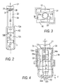
La figure 1 est une vue schématique en coupe partielle de la borne à vis selon l'invention.Figure 1 is a schematic partial sectional view of the screw terminal according to the invention.
La figure 2 est une vue de côté de la borne de la figure 1.Figure 2 is a side view of the terminal of Figure 1.
La figure 3 est une vue de dessus de la borne de la figure 1, avec coupe partielle selon III-III.FIG. 3 is a view from above of the terminal of FIG. 1, with partial section according to III-III.
La figure 4 illustre le fonctionnement de la borne à vis. Figure 4 illustrates the operation of the screw terminal.
La borne à vis A représentée est destinée à être logée dans un appareil électrique.
Les seuls éléments de l'appareil représentés sur la figure 1 sont le logement isolant
10 prévu pour la borne et une branche fixe de contact de la pièce électrique conductrice
rigide 11 contre laquelle on souhaite serrer un ou plusieurs conducteurs ;
ainsi, deux conducteurs C1,C2 susceptibles d'être introduits respectivement audessus
et au-dessous de la branche sont représentés figure 1. Le logement 10 est
situé dans l'appareil, cela signifiant qu'il est prévu dans une partie du boítier de l'appareil
ou dans un bornier rapporté au boítier de l'appareil.The screw terminal A shown is intended to be housed in an electrical device.
The only elements of the apparatus shown in FIG. 1 are the
La borne A comprend une cage 12 de type bien connu, formée par une portion de
bande métallique découpée et pliée pour se boucler en anneau rigide et sensiblement
rectangulaire. La cage rigide 12 comporte sur un petit côté 12a un orifice taraudé
12b et la branche de contact de la pièce conductrice 11 est engagée transversalement
dans l'ouverture allongée 12c, par exemple sensiblement rectangulaire,
de la cage 12.Terminal A comprises a
La vis 20 comprend une tête de manoeuvre 21, une tige filetée 22 et un col 23 reliant
la tige filetée à la tête. La tige filetée, ou un prolongement non fileté de cette
tige, se termine à son extrémité libre par une portée 24.The
Une pièce de pression 30 est couplée à la vis 20 de manière à se déplacer avec
elle. La pièce 30 est une pièce unitaire élastique, sensiblement fermée sur elle-même
en forme d'anneau et symétrique par rapport à un plan axial P de la vis . Elle
comprend une plage de tête 31 située sous la tête 21 et enserrant le col 23 de la
vis, une plage de pression 32 applicable sur le conducteur C1 ou la branche de
contact de la pièce conductrice 11 et, de chaque côté de l'axe de la vis, une aile
concave 33,34 qui se raccorde aux plages 31,32 par une zone de raccordement
déterminant un angle saillant 35. La concavité des ailes (voir cette concavité en vue
latérale sur les figures 1 et 4) est telle qu'elles se rapprochent en leur milieu de l'axe
de la vis. La plage de tête 31 comprend deux demi-secteurs circulaires 31a,31b qui
s'engagent dans le col 23 de la vis et assurent ainsi un maintien équilibré de la
pièce 30. Les demi-secteurs composant la plage de tête 31 sont orientés de façon à
remonter vers la tête de la vis, en donnant une forme générale pentue ou convexe à
la plage de tête, et la plage 31 se termine au-delà des demi-secteurs par des rabattements
axiaux jointifs 31 c qui se rejoignent selon le plan axial P de la vis.A
La plage de pression 32 est incurvée pour donner une forme générale convexe à la
partie inférieure de la pièce 30 et présente des reliefs 32a coopérant avec une partie
en retrait 11 a de la pièce conductrice 11.The
Comme on le voit sur les figures 1 et 4, la pièce 30 est agencée pour que la concavité
de ses ailes 33,34, en combinaison avec la forme pentue ou convexe de ses
plages 31,32, lui permette de se déformer par compression, avec une courbure qui
diminue quand la pression augmente. On notera que la diminution de concavité
s'accompagne du maintien de la pièce 30 dans le gabarit a défini par les angles
saillants 35, ce gabarit étant lui-même ― par nécessité de guidage ― inférieur à la
largeur b du logement 10.As seen in Figures 1 and 4, the
Au repos, une faible distance c est prévue entre la portée d'appui 24 de la vis et la
face interne en regard 32a de la plage de pression 32, cette distance c étant déterminée
pour que son rattrapage produise le niveau souhaité de contrainte de la
pièce de pression. La distance minimale d (observée au repos) entre les faces internes
33a,34a des ailes 33,34 est légèrement supérieure à la largeur e de la cage
12, de manière que la cage puisse glisser librement entre les ailes ou vice versa. La
tête 21 de la vis s'applique sur la plage de tête 31 de la pièce de pression dans une
région située à une faible distance f de l'axe de la vis, de manière à créer via la
plage 31 un bras de levier qui accentue le couple exercé sur la pièce 30.At rest, a small distance c is provided between the
Le logement isolant 10 présente sur ses parois internes au moins une saillie de
maintien 10a qui coopère avec l'avancée formée à l'angle supérieur de la pièce de
pression pour retenir la borne en position ouverte. D'autre part, une bavette isolante
36 qui réduit les risques de contact intempestif est fixée sur l'aile 34, de façon à se
déplacer avec la pièce de pression et à masquer en partie une ouverture d'introduction
de conducteur. Des zones poinçonnées de décompression 36 peuvent être
prévues dans la région fortement sollicitée des angles 35. The insulating
Le fonctionnement de la borne va maintenant être décrit. On notera que, suivant l'appareil auquel la borne est associée, celle-ci serre un conducteur supérieur C1 ou un conducteur inférieur C2 ou deux conducteurs C1 et C2 ; les mouvements de translation de la vis et de la cage sont variables selon les cas d'utilisation.The operation of the terminal will now be described. It will be noted that, following the device to which the terminal is associated, this clamps an upper conductor C1 or a lower conductor C2 or two conductors C1 and C2; movements of translation of the screw and the cage are variable depending on the use case.
Au serrage d'un conducteur C1 par exemple, la rotation de la vis entraíne, par coopération
de son filetage avec l'orifice taraudé 12b, la montée de la cage 12 jusqu'à
sa butée contre la face inférieure de la branche conductrice fixe 11, ainsi que la
descente de la vis relativement à la cage 12, et au logement 10. Cette descente
s'effectue jusqu'à butée de l'aire inférieure de la plage de pression 32 contre la face
en regard de la branche 11. La poursuite de la rotation de la vis entraíne alors la
mise en contrainte par compression de la pièce de pression 30, qui se traduit par la
diminution de la concavité des ailes 33,34 et l'application de la portée 24 de la vis
contre la face interne 32a de la plage de pression 32 (situation indiquée en tirets sur
la partie gauche de la figure 4). Il convient de noter que la tête de vis sollicite la
plage de tête en compression, ce qui est favorable pour respecter la limite élastique
de la pièce 30. L'effort élastique emmagasiné dans les ailes 33,34 de la pièce 30
contribue à empêcher un desserrage de la vis par rotation intempestive (action
exercée par la plage de tête 31 sur la tête 21) et à rattraper un jeu dû au fluage du
conducteur C1, par déplacement de la plage de pression 32 relativement à la portée
24 de la vis, avec une amplitude pouvant atteindre c . When tightening a conductor C1, for example, the rotation of the screw causes, by cooperation of its thread with the threaded
Claims (8)
caractérisée par le fait que
characterized by the fact that
Applications Claiming Priority (2)
| Application Number | Priority Date | Filing Date | Title |
|---|---|---|---|
| FR0107624A FR2825838B1 (en) | 2001-06-06 | 2001-06-06 | SCREW TERMINAL |
| FR0107624 | 2001-06-06 |
Publications (2)
| Publication Number | Publication Date |
|---|---|
| EP1271697A1 true EP1271697A1 (en) | 2003-01-02 |
| EP1271697B1 EP1271697B1 (en) | 2015-08-12 |
Family
ID=8864187
Family Applications (1)
| Application Number | Title | Priority Date | Filing Date |
|---|---|---|---|
| EP02077305.7A Expired - Lifetime EP1271697B1 (en) | 2001-06-06 | 2002-06-04 | Screw terminal |
Country Status (6)
| Country | Link |
|---|---|
| US (1) | US6719593B2 (en) |
| EP (1) | EP1271697B1 (en) |
| JP (1) | JP4060128B2 (en) |
| CN (1) | CN1271747C (en) |
| ES (1) | ES2548058T3 (en) |
| FR (1) | FR2825838B1 (en) |
Cited By (1)
| Publication number | Priority date | Publication date | Assignee | Title |
|---|---|---|---|---|
| EP2383841A2 (en) | 2010-04-30 | 2011-11-02 | Schneider Electric Industries SAS | Connecting system enabling the tightening torque of a screw terminal to be indicated |
Families Citing this family (10)
| Publication number | Priority date | Publication date | Assignee | Title |
|---|---|---|---|---|
| TWI263384B (en) * | 2002-12-19 | 2006-10-01 | Fuji Electric Co Ltd | Terminal device for electrical equipment |
| CN101246999B (en) * | 2007-02-14 | 2011-03-30 | 吴智远 | Wire-clamping seat of conductor terminal seat and its tooth section production method |
| DE112007003529A5 (en) * | 2007-04-03 | 2010-03-04 | Siemens Aktiengesellschaft | Terminal connection device for an electrical conductor, in particular an electrical conductor with a cable lug |
| US7404745B1 (en) * | 2007-04-03 | 2008-07-29 | Chih-Yuan Wu | Terminal contact and clamp assembly for a cable terminal block and method for processing the same |
| FR2986664B1 (en) * | 2012-02-03 | 2014-02-14 | Abb France | ELECTRICAL CONNECTION TERMINAL |
| FR3012685B1 (en) * | 2013-10-29 | 2017-10-20 | Schneider Electric Ind Sas | CLAMPING TERMINAL OF AN ELECTRICAL CONNECTION |
| US9812829B1 (en) | 2016-11-10 | 2017-11-07 | Schneider Electric USA, Inc. | Wiring connector for two wire to two point connection |
| WO2020157563A2 (en) * | 2019-01-29 | 2020-08-06 | Appleton Grp, Llc | A heat-absorbing-and-dissipating jacket for a terminal of an electrical device |
| DE102021112258A1 (en) | 2021-05-11 | 2022-11-17 | Weidmüller Interface GmbH & Co. KG | connection device |
| DE202022103614U1 (en) * | 2022-06-29 | 2022-11-23 | Raycap Ip Development Ltd. | Modular surge protective device assemblies and electrical systems incorporating the same |
Citations (9)
| Publication number | Priority date | Publication date | Assignee | Title |
|---|---|---|---|---|
| NL63870C (en) * | 1900-01-01 | |||
| DE712382C (en) * | 1940-05-07 | 1941-10-17 | Walter Luedicke | Connection or connecting terminal for electrical conductors |
| DE733024C (en) * | 1939-11-05 | 1943-03-17 | Versuchsanstalt Fuer Luftfahrt | Spring clamp, especially for light metal cables |
| CH325260A (en) * | 1953-07-08 | 1957-10-31 | Siemens Ag | Clamp with a spring-loaded frame, especially for light metal cables |
| DE1935560U (en) | 1964-02-21 | 1966-03-31 | Georg Schlegel Elektrotechnisc | CONNECTION TERMINAL FOR ONE OR MORE ELECTRICAL CONDUCTORS. |
| DE2147046A1 (en) * | 1971-09-21 | 1973-04-05 | Phoenix Elekt | ELECTRICAL CONNECTING TERMINAL, IN PARTICULAR HIGH CURRENT LINE TERMINAL |
| DE4013225A1 (en) | 1990-04-26 | 1991-10-31 | Abb Patent Gmbh | SCREW CONNECTION TERMINAL, ESPECIALLY FOR A SWITCHGEAR ACCESSIBLE TO SIMILAR OR SIMILAR DEVICES |
| DE4102581A1 (en) | 1991-01-29 | 1992-08-06 | Siemens Ag | Series connection terminal for conductors of different dia. - incorporates clamp comprising fixed central body, freely movable clamping element and screw working into sub-divided space |
| EP0865128A1 (en) * | 1997-03-10 | 1998-09-16 | Siemens Aktiengesellschaft | Distribution system |
Family Cites Families (14)
| Publication number | Priority date | Publication date | Assignee | Title |
|---|---|---|---|---|
| US2602104A (en) * | 1946-08-13 | 1952-07-01 | Hubbell Inc Harvey | Wire connector for electrical receptacles |
| US2809363A (en) * | 1954-08-21 | 1957-10-08 | Siemens Ag | Electrical connectors |
| US3659253A (en) * | 1970-02-28 | 1972-04-25 | Siemens Ag | Frame clamp for electrically connecting electrical leads |
| US3836914A (en) * | 1972-12-20 | 1974-09-17 | Mead Corp | Catcher for a jet drop recorder |
| US3836941A (en) * | 1973-07-05 | 1974-09-17 | Thomas & Betts Corp | Electrical connector with resilient pressure pad |
| US3864005A (en) * | 1973-10-11 | 1975-02-04 | Gen Electric | Resilient electrical terminal connector |
| US4103986A (en) * | 1977-09-12 | 1978-08-01 | Thomas & Betts Corporation | Electrical terminal |
| US4213669A (en) * | 1978-09-11 | 1980-07-22 | Gte Sylvania Wiring Devices Incorporated | Terminal collar |
| DE3412317A1 (en) * | 1984-04-03 | 1985-10-03 | C.A. Weidmüller GmbH & Co, 4930 Detmold | LADDER CONNECTION FOR LAMINATED PCB |
| DE69423658T2 (en) * | 1994-12-09 | 2000-07-13 | Jonan Denki Seiki Ltd | CONNECTION BLOCK |
| US5747741A (en) * | 1995-06-16 | 1998-05-05 | Hubert Laurenz Naimer | Screw terminal for an electrical connection of cables or wires |
| US6040525A (en) * | 1996-04-18 | 2000-03-21 | Erico International Corporation | Electrical clip and method |
| US6004197A (en) * | 1997-01-23 | 1999-12-21 | Hao Chien Chao | Ergonomically friendly random orbital sander construction |
| DE19716762C2 (en) * | 1997-04-12 | 2002-02-28 | Wago Verwaltungs Gmbh | Shield terminal |
-
2001
- 2001-06-06 FR FR0107624A patent/FR2825838B1/en not_active Expired - Fee Related
-
2002
- 2002-06-04 EP EP02077305.7A patent/EP1271697B1/en not_active Expired - Lifetime
- 2002-06-04 ES ES02077305.7T patent/ES2548058T3/en not_active Expired - Lifetime
- 2002-06-06 US US10/162,567 patent/US6719593B2/en not_active Expired - Lifetime
- 2002-06-06 JP JP2002165506A patent/JP4060128B2/en not_active Expired - Lifetime
- 2002-06-06 CN CNB021410143A patent/CN1271747C/en not_active Expired - Fee Related
Patent Citations (9)
| Publication number | Priority date | Publication date | Assignee | Title |
|---|---|---|---|---|
| NL63870C (en) * | 1900-01-01 | |||
| DE733024C (en) * | 1939-11-05 | 1943-03-17 | Versuchsanstalt Fuer Luftfahrt | Spring clamp, especially for light metal cables |
| DE712382C (en) * | 1940-05-07 | 1941-10-17 | Walter Luedicke | Connection or connecting terminal for electrical conductors |
| CH325260A (en) * | 1953-07-08 | 1957-10-31 | Siemens Ag | Clamp with a spring-loaded frame, especially for light metal cables |
| DE1935560U (en) | 1964-02-21 | 1966-03-31 | Georg Schlegel Elektrotechnisc | CONNECTION TERMINAL FOR ONE OR MORE ELECTRICAL CONDUCTORS. |
| DE2147046A1 (en) * | 1971-09-21 | 1973-04-05 | Phoenix Elekt | ELECTRICAL CONNECTING TERMINAL, IN PARTICULAR HIGH CURRENT LINE TERMINAL |
| DE4013225A1 (en) | 1990-04-26 | 1991-10-31 | Abb Patent Gmbh | SCREW CONNECTION TERMINAL, ESPECIALLY FOR A SWITCHGEAR ACCESSIBLE TO SIMILAR OR SIMILAR DEVICES |
| DE4102581A1 (en) | 1991-01-29 | 1992-08-06 | Siemens Ag | Series connection terminal for conductors of different dia. - incorporates clamp comprising fixed central body, freely movable clamping element and screw working into sub-divided space |
| EP0865128A1 (en) * | 1997-03-10 | 1998-09-16 | Siemens Aktiengesellschaft | Distribution system |
Cited By (4)
| Publication number | Priority date | Publication date | Assignee | Title |
|---|---|---|---|---|
| EP2383841A2 (en) | 2010-04-30 | 2011-11-02 | Schneider Electric Industries SAS | Connecting system enabling the tightening torque of a screw terminal to be indicated |
| FR2959613A1 (en) * | 2010-04-30 | 2011-11-04 | Schneider Electric Ind Sas | CONNECTING SYSTEM FOR SIGNALING THE TIGHTENING TORQUE OF A SCREW TERMINAL. |
| EP2383841A3 (en) * | 2010-04-30 | 2012-03-28 | Schneider Electric Industries SAS | Connecting system enabling the tightening torque of a screw terminal to be indicated |
| US8393922B2 (en) | 2010-04-30 | 2013-03-12 | Schneider Electric Industries Sas | Connection system enabling the tightening torque of a screw terminal to be indicated |
Also Published As
| Publication number | Publication date |
|---|---|
| EP1271697B1 (en) | 2015-08-12 |
| CN1271747C (en) | 2006-08-23 |
| JP2003223942A (en) | 2003-08-08 |
| US6719593B2 (en) | 2004-04-13 |
| ES2548058T3 (en) | 2015-10-13 |
| JP4060128B2 (en) | 2008-03-12 |
| CN1389957A (en) | 2003-01-08 |
| FR2825838A1 (en) | 2002-12-13 |
| US20020187685A1 (en) | 2002-12-12 |
| FR2825838B1 (en) | 2006-12-29 |
Similar Documents
| Publication | Publication Date | Title |
|---|---|---|
| EP1271697B1 (en) | Screw terminal | |
| EP2725660B1 (en) | Flexible tunnel for a connection terminal | |
| EP2007991B1 (en) | Clamping device | |
| EP2430321B1 (en) | Device for attaching a first part to a second part which is attached to a third part and the assembly of three parts, in particular, of a motor vehicle | |
| FR2528137A1 (en) | BRAKE JAW ARRANGEMENT AND JAW SPRING INCLUDED IN THIS ARRANGEMENT | |
| EP0688063B1 (en) | Electrical apparatus with clamping screw | |
| EP0559585A1 (en) | Connector terminal with caliper of variable thickness and mounted nut | |
| FR2862443A1 (en) | ELECTRICAL CONNECTION TERMINAL AND ELECTRICAL PROTECTION APPARATUS COMPRISING SUCH A TERMINAL | |
| EP1231422B1 (en) | Process for making a screw unloseable, fixation collars for pipes and use of the process to manufacture the collars | |
| FR2722546A1 (en) | SCREW WITH CAGE HEAD FOR BLIND MOUNTING IN THE OPENING OF A PANEL BY EXAMPLE | |
| FR2862441A1 (en) | ENLARGED TIGHTENING ROPE CABLE CLAMP AND JUNCTION BLOCK PROVIDED WITH SUCH A CABLE CLAMP | |
| FR2908239A1 (en) | Electrical supply cable locking and maintaining device for electric household appliance e.g. electric heating equipment, has cap assuring maintenance function after assembly due to cooperation of external edges in openings of support | |
| EP2034559B1 (en) | Electrical connection device, application and method of use | |
| EP1607644A2 (en) | Ball joint and its use for a clutch control | |
| FR2619252A1 (en) | JOINT BONDING SYSTEM FOR ELEMENTS WORKING IN HIGH FREQUENCY | |
| FR2894721A1 (en) | Conductive pad and stripped electric wire`s conductors connecting clamping saddle, has clamping screw with flange and screwed in wall of casing opposite to surface, where screw clamps one conductor on another conductor placed on surface | |
| EP2904623B1 (en) | Electrical contact device of the contact finger type with a strong nominal current | |
| EP2115817B1 (en) | Connection block with means for retaining a conductive rod | |
| FR2613877A1 (en) | Terminal lug for electrical connection | |
| FR2966648A1 (en) | Electric cable for coupling e.g. equipments of car, has protuberance defining shoulder oriented toward terminal connection part and avoiding translation of thermo-retracted sealing sheath on part of protection sheath and mounting body | |
| FR2851309A1 (en) | Standard tenonned nut, is confined in plastic case whose exterior surface is centered by interior surface of rigid support, where case comprises of interior pattern complementary to exterior pattern of nut | |
| FR2776842A3 (en) | Spring arm contact element for plug-in connector | |
| BE442070A (en) | ||
| FR2903815A1 (en) | Electrical cable connecting terminal for electrical equipment of house, has beam engaged in unit when beam is disengaged from plate, and plate made of copper and copper alloy, where plate has length smaller than that of beam`s axial length | |
| FR2675639A1 (en) | Screw-clamp assembly for electrical appliance terminal |
Legal Events
| Date | Code | Title | Description |
|---|---|---|---|
| PUAI | Public reference made under article 153(3) epc to a published international application that has entered the european phase |
Free format text: ORIGINAL CODE: 0009012 |
|
| AK | Designated contracting states |
Kind code of ref document: A1 Designated state(s): AT BE CH CY DE DK ES FI FR GB GR IE IT LI LU MC NL PT SE TR |
|
| AX | Request for extension of the european patent |
Free format text: AL;LT;LV;MK;RO;SI |
|
| 17P | Request for examination filed |
Effective date: 20030127 |
|
| AKX | Designation fees paid |
Designated state(s): CH DE ES FR IT LI |
|
| RAP1 | Party data changed (applicant data changed or rights of an application transferred) |
Owner name: SCHNEIDER ELECTRIC INDUSTRIES SAS |
|
| 17Q | First examination report despatched |
Effective date: 20100722 |
|
| GRAP | Despatch of communication of intention to grant a patent |
Free format text: ORIGINAL CODE: EPIDOSNIGR1 |
|
| INTG | Intention to grant announced |
Effective date: 20150513 |
|
| GRAS | Grant fee paid |
Free format text: ORIGINAL CODE: EPIDOSNIGR3 |
|
| GRAA | (expected) grant |
Free format text: ORIGINAL CODE: 0009210 |
|
| AK | Designated contracting states |
Kind code of ref document: B1 Designated state(s): CH DE ES FR IT LI |
|
| REG | Reference to a national code |
Ref country code: CH Ref legal event code: EP |
|
| REG | Reference to a national code |
Ref country code: DE Ref legal event code: R096 Ref document number: 60247378 Country of ref document: DE |
|
| REG | Reference to a national code |
Ref country code: ES Ref legal event code: FG2A Ref document number: 2548058 Country of ref document: ES Kind code of ref document: T3 Effective date: 20151013 |
|
| REG | Reference to a national code |
Ref country code: FR Ref legal event code: PLFP Year of fee payment: 15 |
|
| REG | Reference to a national code |
Ref country code: DE Ref legal event code: R097 Ref document number: 60247378 Country of ref document: DE |
|
| PLBE | No opposition filed within time limit |
Free format text: ORIGINAL CODE: 0009261 |
|
| STAA | Information on the status of an ep patent application or granted ep patent |
Free format text: STATUS: NO OPPOSITION FILED WITHIN TIME LIMIT |
|
| 26N | No opposition filed |
Effective date: 20160513 |
|
| REG | Reference to a national code |
Ref country code: FR Ref legal event code: PLFP Year of fee payment: 16 |
|
| REG | Reference to a national code |
Ref country code: DE Ref legal event code: R084 Ref document number: 60247378 Country of ref document: DE |
|
| REG | Reference to a national code |
Ref country code: FR Ref legal event code: PLFP Year of fee payment: 17 |
|
| PGFP | Annual fee paid to national office [announced via postgrant information from national office to epo] |
Ref country code: IT Payment date: 20190621 Year of fee payment: 18 |
|
| PGFP | Annual fee paid to national office [announced via postgrant information from national office to epo] |
Ref country code: FR Payment date: 20190515 Year of fee payment: 18 |
|
| PGFP | Annual fee paid to national office [announced via postgrant information from national office to epo] |
Ref country code: CH Payment date: 20190620 Year of fee payment: 18 |
|
| PGFP | Annual fee paid to national office [announced via postgrant information from national office to epo] |
Ref country code: ES Payment date: 20190701 Year of fee payment: 18 |
|
| PGFP | Annual fee paid to national office [announced via postgrant information from national office to epo] |
Ref country code: DE Payment date: 20200603 Year of fee payment: 19 |
|
| REG | Reference to a national code |
Ref country code: CH Ref legal event code: PL |
|
| PG25 | Lapsed in a contracting state [announced via postgrant information from national office to epo] |
Ref country code: FR Free format text: LAPSE BECAUSE OF NON-PAYMENT OF DUE FEES Effective date: 20200630 Ref country code: CH Free format text: LAPSE BECAUSE OF NON-PAYMENT OF DUE FEES Effective date: 20200630 Ref country code: LI Free format text: LAPSE BECAUSE OF NON-PAYMENT OF DUE FEES Effective date: 20200630 |
|
| REG | Reference to a national code |
Ref country code: ES Ref legal event code: FD2A Effective date: 20211026 |
|
| PG25 | Lapsed in a contracting state [announced via postgrant information from national office to epo] |
Ref country code: IT Free format text: LAPSE BECAUSE OF NON-PAYMENT OF DUE FEES Effective date: 20200604 |
|
| REG | Reference to a national code |
Ref country code: DE Ref legal event code: R119 Ref document number: 60247378 Country of ref document: DE |
|
| PG25 | Lapsed in a contracting state [announced via postgrant information from national office to epo] |
Ref country code: ES Free format text: LAPSE BECAUSE OF NON-PAYMENT OF DUE FEES Effective date: 20200605 |
|
| PG25 | Lapsed in a contracting state [announced via postgrant information from national office to epo] |
Ref country code: DE Free format text: LAPSE BECAUSE OF NON-PAYMENT OF DUE FEES Effective date: 20220101 |