EP2007991B1 - Clamping device - Google Patents
Clamping device Download PDFInfo
- Publication number
- EP2007991B1 EP2007991B1 EP07723096.9A EP07723096A EP2007991B1 EP 2007991 B1 EP2007991 B1 EP 2007991B1 EP 07723096 A EP07723096 A EP 07723096A EP 2007991 B1 EP2007991 B1 EP 2007991B1
- Authority
- EP
- European Patent Office
- Prior art keywords
- base
- locking clip
- free ends
- rod
- flexible tongues
- Prior art date
- Legal status (The legal status is an assumption and is not a legal conclusion. Google has not performed a legal analysis and makes no representation as to the accuracy of the status listed.)
- Active
Links
- 210000002105 tongue Anatomy 0.000 claims description 30
- 238000003780 insertion Methods 0.000 claims description 8
- 230000037431 insertion Effects 0.000 claims description 8
- 239000003351 stiffener Substances 0.000 claims description 6
- 230000006835 compression Effects 0.000 description 5
- 238000007906 compression Methods 0.000 description 5
- 239000002184 metal Substances 0.000 description 3
- 230000014759 maintenance of location Effects 0.000 description 2
- 239000000463 material Substances 0.000 description 2
- 238000005452 bending Methods 0.000 description 1
- 230000000903 blocking effect Effects 0.000 description 1
- 230000000295 complement effect Effects 0.000 description 1
- 230000000694 effects Effects 0.000 description 1
- 239000002991 molded plastic Substances 0.000 description 1
Images
Classifications
-
- F—MECHANICAL ENGINEERING; LIGHTING; HEATING; WEAPONS; BLASTING
- F16—ENGINEERING ELEMENTS AND UNITS; GENERAL MEASURES FOR PRODUCING AND MAINTAINING EFFECTIVE FUNCTIONING OF MACHINES OR INSTALLATIONS; THERMAL INSULATION IN GENERAL
- F16B—DEVICES FOR FASTENING OR SECURING CONSTRUCTIONAL ELEMENTS OR MACHINE PARTS TOGETHER, e.g. NAILS, BOLTS, CIRCLIPS, CLAMPS, CLIPS OR WEDGES; JOINTS OR JOINTING
- F16B37/00—Nuts or like thread-engaging members
- F16B37/08—Quickly-detachable or mountable nuts, e.g. consisting of two or more parts; Nuts movable along the bolt after tilting the nut
- F16B37/0807—Nuts engaged from the end of the bolt, e.g. axially slidable nuts
- F16B37/0842—Nuts engaged from the end of the bolt, e.g. axially slidable nuts fastened to the threaded bolt with snap-on-action, e.g. push-on nuts for stud bolts
-
- F—MECHANICAL ENGINEERING; LIGHTING; HEATING; WEAPONS; BLASTING
- F16—ENGINEERING ELEMENTS AND UNITS; GENERAL MEASURES FOR PRODUCING AND MAINTAINING EFFECTIVE FUNCTIONING OF MACHINES OR INSTALLATIONS; THERMAL INSULATION IN GENERAL
- F16B—DEVICES FOR FASTENING OR SECURING CONSTRUCTIONAL ELEMENTS OR MACHINE PARTS TOGETHER, e.g. NAILS, BOLTS, CIRCLIPS, CLAMPS, CLIPS OR WEDGES; JOINTS OR JOINTING
- F16B37/00—Nuts or like thread-engaging members
- F16B37/005—Nuts or like thread-engaging members into which threads are cut during screwing
-
- F—MECHANICAL ENGINEERING; LIGHTING; HEATING; WEAPONS; BLASTING
- F16—ENGINEERING ELEMENTS AND UNITS; GENERAL MEASURES FOR PRODUCING AND MAINTAINING EFFECTIVE FUNCTIONING OF MACHINES OR INSTALLATIONS; THERMAL INSULATION IN GENERAL
- F16B—DEVICES FOR FASTENING OR SECURING CONSTRUCTIONAL ELEMENTS OR MACHINE PARTS TOGETHER, e.g. NAILS, BOLTS, CIRCLIPS, CLAMPS, CLIPS OR WEDGES; JOINTS OR JOINTING
- F16B37/00—Nuts or like thread-engaging members
- F16B37/02—Nuts or like thread-engaging members made of thin sheet material
-
- Y—GENERAL TAGGING OF NEW TECHNOLOGICAL DEVELOPMENTS; GENERAL TAGGING OF CROSS-SECTIONAL TECHNOLOGIES SPANNING OVER SEVERAL SECTIONS OF THE IPC; TECHNICAL SUBJECTS COVERED BY FORMER USPC CROSS-REFERENCE ART COLLECTIONS [XRACs] AND DIGESTS
- Y10—TECHNICAL SUBJECTS COVERED BY FORMER USPC
- Y10T—TECHNICAL SUBJECTS COVERED BY FORMER US CLASSIFICATION
- Y10T24/00—Buckles, buttons, clasps, etc.
- Y10T24/44—Clasp, clip, support-clamp, or required component thereof
Definitions
- Such a device can be used for assembling several parts by axial compression, in particular by tightening the screw-nut type.
- the pieces are, for example, flat elements of the plate, sheet metal, or similar type.
- Claw-shaped nuts have been known for a long time, that is to say having the general shape of a U, and essentially comprising a first branch carrying a screw-in connection connected to a second branch with an orifice for the passage of 'a screw.
- An example of this type of clamping device is described in the document FR2754575 , with a collet nut further comprising a ring-shaped portion cut in a tab folded from the second leg to extend between the two arms of the nut and to center it on one of the elements plans to assemble.
- the tear resistance of the screwing member is relatively low because it is directly related to the mechanical strength of the screwdrivers.
- the latter are constituted, for example, by rigid tongues, punched and stamped from the base, whose free ends are rigidly engaged in the threads of the threaded section.
- the tongues When a very high pulling force is applied to the screw member, it is common for the tongues to deform (axially and / or radially) irreversibly and unexpectedly release the
- the object of the invention is to propose a clamping device which is of simple and inexpensive design, and which makes it possible to facilitate the assembly operation and to make the assembly obtained more reliable.
- the retaining means are constituted by a plurality of flexible and resilient tongues, arranged in a convergent manner so that their free ends determine between them a free space smaller than the nominal diameter of the section. threaded to engage automatically in the threads of the threaded portion during the axial insertion of the rod into the passage hole, and in that a soyer is arranged at the periphery of the passage hole in the direction of the flexible tongues to form a stop at the free ends during the axial withdrawal of the rod.
- the axial insertion movement of the screw member in the locking clip causes the radial spacing of the free ends of the flexible tongues.
- the elasticity of the flexible tongues automatically causes the engagement of their free ends in the threads of the threaded section to ensure the retention and the axial locking of the screwing member with respect to the staple, locking .
- the assembtage is first by a simple axial thrust of the screw member relative to the locking clip, then optionally by a light screwing of the screw member. This feature facilitates assembly through simple and quick manipulation of the screw member.
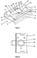
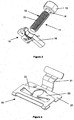
- the Figures 1 to 3 illustrate a first example of clamping device according to the invention, which consists of a locking clip 10 and a screwing member 11.
- the screwing member 11, of metal for example, visible only on the figure 3 comprises a partially threaded rod 12 and a bearing head 13, at the so-called proximal end.
- the rod 12 comprises a smooth upper section 14 located near the support head 13 and a lower threaded section 15 extending to the opposite end, called the distal end.
- the locking clip 10 is shaped as a jumper having a generally U-shaped, with first and second legs 16, 17 substantially parallel.
- the locking clip 10 is obtained by cutting, then folding, a metal plate.
- clamping device will be described in a particular example of application in no way limiting, namely for the assembly of flat elements of the plate, panel, sheet or similar type. Nevertheless, it goes without saying that the clamping device can be used, more generally, in all applications requiring a screw-nut type system.
- one of the planar elements to be assembled is intended to be housed between the branches 16, 17 of the locking clip 10.
- the other flat elements of the assembly are not shown.
- the branches 16, 17 may have a slight convergence to allow pre-assembly and fixing of the locking clip 10 on the planar element 18, before the final assembly made in cooperation with the screwing member 11.
- the first branch 16 comprises a hole for the passage of the rod 12 of the screwing member 11, as well as the second branch 17, respectively referenced 19, 20.
- the first branch 16 ends with a folded portion 24 towards the outside intended to facilitate the establishment of the locking clip 10 on the plane element 18.
- the second branch 17 constitutes a notched base 21 supporting two flexible tongues 22, 23 and elastics, arranged relative to the base 21 on the side opposite to the first branch 16.
- the flexible tongues 22, 23 are arranged to be convergent so that their free ends, respectively referenced 221, 231, are located vertically to the through hole 20 and define between them a free space noted d, less than the nominal diameter of the threaded portion 15.
- Each free end 221, 231 has a circular recess a diameter corresponding to the internal diameter of the thread constituting the threaded portion 15.
- the ends 222, 232 of the flexible tongues 22, 23, opposite the free ends 221, 231, are respectively integral with a connecting arm 25, 26 connected to the base 21 by a folded portion 27 at 180 °, constituting an elastically deformable zone.
- the link arms 25, 26 are perpendicular to their respective flexible tongues 22, 23.
- the flexible tongues 22, 23 and the connecting arms 25, 26 are coplanar, and parallel to the base 21.
- the link arms 25, 26 are interconnected by a stiffener 28, rectilinear in The example.
- the locking clip 10 is first pre-assembled and fixed on the plane element 18. Then, the other element or elements planes intended to be assembled with the element 18, are superposed and positioned against the first branch 16 or close to the outside of the locking clip 10.
- Each planar element is provided with an orifice intended to be traversed axially by the rod 12.
- the planar elements may each be integral with a respective part of any shape, said parts (not shown) being intended to be assembled together in an area where the planar elements are superimposed and can be assembled by Tightening.
- the rod 12 of the screwing member 11 is inserted into the orifices of the flat elements to be assembled with the element 18, from the distal end towards the proximal end, then into the through hole 19. , then through the plane element 18, then into the through hole 20, until it comes into contact with the free ends 221, 231 of the flexible tongues 22, 23.
- the axial insertion of the rod 12 into the locking clip 10 then causes flexing of the flexible tongues 22, 23 such that their free ends 221, 231 move axially away from the through hole 20 of the base 21.
- this bending movement of the flexible tongues 22, 23 is accompanied by the spacing of the free ends 221, 231 in the radial direction, thereby increasing the free space d.
- These axial and radial movements of the free ends 221, 231 are facilitated and amplified by the presence of the deformable zones formed by the folded portions 27.
- the stiffener 28 eliminates, or at least limits, the possibility of rotation of the link arms 25 and 26 along the axis perpendicular to the plane of the base 21.
- the support head 13 abuts against the corresponding planar element, and the elasticity of the flexible tongues 22, 23 automatically causes the engagement of their free ends 221, 231 in the threads of the threaded portion 15.
- the recesses are supported linearly against the bottom of the threads to ensure the retention and axial locking of the screw member 11 relative to the locking clip 10.
- the section of the flexible tongues 22, 23 at the opposite ends 222, 232 is determined to allow a rotation of the free ends 221, 231 by torsion of the flexible tongues 22, 23, so as to be oriented according to the angle of inclination of threads of the threaded portion 15. This aspect strengthens the torque resistance of the locking clip 10.
- the axial blocking ensures the clamping, and therefore the assembly, of the planar element 18 with the other flat elements.
- the assembly of the planar elements 18 and others is first by a simple axial thrust of the screwing member 11 relative to the locking clip 10, then optionally by a light screwing of the screwing member 11. This feature facilitates assembly by simple and quick manipulation of the screw member 11.
- the locking clip 10 and the screwing member 11 may be made of other suitable materials, varying according to the applications, such as molded plastic.
- the number of flexible tongues 22, 23 may vary according to the applications, depending, for example, on the material constituting the locking clip 10 and / or the desired rigidity during the axial insertion of the locking tab. the screwing member 11 and / or the tear resistance sought.
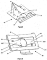
- the figures 4 and 5 represent respectively the locking clips 30 and 40 of two other embodiments of clamping device according to the invention, used in different applications.
- the locking clip 30 ( figure 4 ) differs from the locking clip 10 in that the first branch 16 is removed.
- the operation of the base 21 and the flexible tongues 22, 23 remains identical. From one of the edges of the base 21 extends a fixing lug 31 adapted to fit into a complementary housing provided in a first part to be clamped against a second part held by the support head 13.
- the first and second pieces are constituted, for example, by the two articulated half-bores of a pipe clamp.
- the locking clip 40 ( figure 5 ) differs from the locking clip 30 by the fact that the fixing lug 31 is removed and that the base 21 has greater dimensions at least in one of the directions, so as to be able to arrange a plurality of holes 41.
- the fixing holes 41 allow, for example, overmoulding of one of the parts to be clamped on the locking clip 40, or the fixing of the clip on one of the parts to be clamped by the intermediate screw.
- the figure 6 illustrates the locking clip 50 of a fourth embodiment of a clamping device according to the invention.
- the locking clip 50 differs from the locking clip 30 in that the connecting arms 25, 26 extend beyond their junction with the opposite ends 222, 232 of the flexible tabs 22, 23.
- free ends 251, 261 of the connecting arms, opposed to the ends connected to the base 21, are interconnected by a stiffener 51.
- the linkage arms 25, 26 and the stiffeners 28, 51 constitute a stiffening frame for removing any possibility of radial movement of the free ends 221, 231 other than that caused by the flexion of the flexible tongues 22, 23 during the insertion of the screwing member 11. This feature increases the resistance to tearing of the screwing 11 as well as the torque resistance of the locking clip 50.
Description
L'invention concerne un dispositif de serrage comprenant :
- un organe de vissage avec une tête d'appui et une tige munie d'un tronçon fileté,
- une agrafe de verrouillage comportant une embase équipée d'un trou de passage de la tige de l'organe de vissage, et des moyens de retenue supportés par l'embase pour être agencés à la verticale du trou de passage, et aptes à coopérer avec le tronçon fileté pour créer un blocage axial entre l'organe de vissage et l'agrafe de verrouillage.
- a screwing member with a support head and a rod provided with a threaded section,
- a locking clip comprising a base equipped with a hole for passage of the rod of the screwing member, and retaining means supported by the base to be arranged vertically of the through hole, and able to cooperate with the threaded section to create an axial locking between the screw member and the locking clip.
Un tel dispositif peut être utilisé pour des assemblages de plusieurs pièces par une compression axiale, notamment par serrage du type vis-écrou. Les pièces sont, par exemple, des éléments plans du type plaques, panneaux tôles, ou analogues. On connaît depuis longtemps des écrous en forme de pince, c'est-à-dire présentant la forme générale d'un U, et comprenant essentiellement une première branche portant une empreinte de vissage reliée à une deuxième branche avec un orifice pour le passage d'une vis. Un exemple de ce type de dispositif de serrage est décrit dans le document
Mais les dispositifs de serrage connus ne sont pas complètement satisfaisants car les moyens de retenue destinés à coopérer avec le tronçon fileté de la tige sont réalisés par des empreintes de vissage dans lesquelles peuvent venir en prise les filets de ce tronçon. Pour assurer le serrage lors de l'assemblage, il est donc nécessaire de visser l'organe de vissage pour que ce dernier se translate selon un mouvement hélicoïdal par rapport à l'agrafe de verrouillage jusqu'à provoquer le serrage désiré. Le temps de montage et de manipulation pour réaliser un tel assemblage est long, notamment lorsque les dimensions des pièces à assembler nécessitent plusieurs dispositifs de serrage. Ce temps est directement lié à la longueur du tronçon fileté et à l'agencement relatif entre les pièces. Cet inconvénient présente d'autant plus d'importance que les dispositifs de serrage sont utilisés dans les chaînes finales d'assemblage, lesquelles sont généralement les plus coûteuses.But known clamping devices are not completely satisfactory because the retaining means for cooperating with the threaded portion of the rod are made by screwing recesses in which can engage the threads of this section. To ensure tightness during assembly, it is therefore necessary to screw the screw member so that the latter is translated in a helical movement relative to the locking clip to cause the desired tightening. The assembly and handling time for making such an assembly is long, especially when the dimensions of the parts to be assembled require several clamping devices. This time is directly related to the length of the threaded section and the relative arrangement between the parts. This disadvantage is all the more important as the clamping devices are used in the final assembly lines, which are generally the most expensive.
Par ailleurs, la résistance à l'arrachement de l'organe de vissage est relativement faible car elle est directement liée à la tenue mécanique des empreintes de vissage. Or, ces dernières sont constituées, par exemple, par des languettes rigides, poinçonnées et embouties à partir de l'embase, dont les extrémités libres sont engagées rigidement dans les filets du tronçon fileté. Lorsqu'un effort d'arrachement très élevé est appliqué à l'organe de vissage, il est fréquent que les languettes se déforment (axialement et/ou radialement) de manière irréversible et libèrent inopinément l'organe deFurthermore, the tear resistance of the screwing member is relatively low because it is directly related to the mechanical strength of the screwdrivers. However, the latter are constituted, for example, by rigid tongues, punched and stamped from the base, whose free ends are rigidly engaged in the threads of the threaded section. When a very high pulling force is applied to the screw member, it is common for the tongues to deform (axially and / or radially) irreversibly and unexpectedly release the
Le document
L'invention a pour but de proposer un dispositif de serrage qui soit de conception simple et peu onéreuse, et qui permette de faciliter l'opération d'assemblage et de fiabiliser l'assemblage obtenu.The object of the invention is to propose a clamping device which is of simple and inexpensive design, and which makes it possible to facilitate the assembly operation and to make the assembly obtained more reliable.
Selon l'invention, ce but est atteint par le fait que les moyens de retenue sont constitués par une pluralité de languettes flexibles et élastiques, agencées de manière convergente de sorte que leurs extrémités libres déterminent entre elles un espace libre inférieur au diamètre nominal du tronçon fileté pour venir s'engager automatiquement dans les filets du tronçon fileté lors de l'insertion axiale de la tige dans le trou de passage, et par le fait qu'un soyer est agencé à la périphérie du trou de passage en direction des languettes flexibles pour constituer une butée aux extrémités libres lors du retrait axial de la tige.According to the invention, this object is achieved by the fact that the retaining means are constituted by a plurality of flexible and resilient tongues, arranged in a convergent manner so that their free ends determine between them a free space smaller than the nominal diameter of the section. threaded to engage automatically in the threads of the threaded portion during the axial insertion of the rod into the passage hole, and in that a soyer is arranged at the periphery of the passage hole in the direction of the flexible tongues to form a stop at the free ends during the axial withdrawal of the rod.
Le mouvement d'insertion axiale de l'organe de vissage dans l'agrafe de verrouillage provoque l'écartement radial des extrémités libres des languettes flexibles. En fin d'insertion, l'élasticité des languettes flexibles provoque automatiquement l'engagement de leurs extrémités libres dans les filets du tronçon fileté pour assurer la retenue et le blocage axial de l'organe de vissage par rapport à l'agrafe, de verrouillage. Pour augmenter l'effort de serrage par compression axiale, il suffit ensuite à l'opérateur de visser légèrement l'organe de vissage jusqu'à une valeur désirée de couple de serrage. En d'autres termes, l'assembtage, se fait d'abord par une simple poussée axiale de l'organe de vissage par rapport à l'agrafe de verrouillage, puis de manière facultative par un léger vissage de l'organe de vissage. Cette caractéristique facilite l'assemblage grâce à une manipulation simple et rapide de l'organe de vissage.The axial insertion movement of the screw member in the locking clip causes the radial spacing of the free ends of the flexible tongues. At the end of insertion, the elasticity of the flexible tongues automatically causes the engagement of their free ends in the threads of the threaded section to ensure the retention and the axial locking of the screwing member with respect to the staple, locking . To increase the compression force by axial compression, it is then sufficient for the operator to slightly screw the screw member to a desired value of tightening torque. In other words, the assembtage, is first by a simple axial thrust of the screw member relative to the locking clip, then optionally by a light screwing of the screw member. This feature facilitates assembly through simple and quick manipulation of the screw member.
Lorsqu'un effort d'arrachement est appliqué à l'organe de vissage, les extrémités libres des languettes viennent prendre appui sur l'extrémité du soyer. La mobilité radiale et axiale des extrémités libres des languettes flexibles est alors supprimée. La résistance à l'arrachement de l'organe de vissage, assurant la tenue mécanique du dispositif de serrage, est par conséquent très élevée, ce qui contribue à fiabiliser l'assemblage.When a pulling force is applied to the screw member, the free ends of the tongues come to bear on the end of the soyer. The radial and axial mobility of the free ends of the flexible tongues is then removed. The resistance to tearing of the screw member, ensuring the mechanical strength of the clamping device, is therefore very high, which contributes to reliability of the assembly.
D'autres avantages et caractéristiques ressortiront plus clairement de la description qui va suivre de modes particuliers de réalisation de l'invention donnés à titre d'exemples non limitatifs et représentés aux dessins annexés, dans lesquels :
- la
figure 1 est une vue en perspective de l'agrafe de verrouillage d'un premier exemple de réalisation de dispositif de serrage selon l'invention, - la
figure 2 est une vue en coupe longitudinale de l'agrafe de verrouillage de lafigure 1 , - la
figure 3 est une vue en perspective du premier exemple de dispositif de serrage, représentant un élément plan à assembler et l'agrafe de verrouillage en coupe transversal, - la
figure 4 est une vue en perspective de l'agrafe de verrouillage d'un deuxième exemple de réalisation de dispositif de serrage selon l'invention, - la
figure 5 est une vue en perspective de l'agrafe de verrouillage d'un troisième exemple de réalisation de dispositif de serrage selon l'invention, - la
figure 6 est une vue en perspective de l'agrafe de verrouillage d'un quatrième exemple de réalisation de dispositif de serrage selon l'invention.
- the
figure 1 is a perspective view of the locking clip of a first embodiment of a clamping device according to the invention, - the
figure 2 is a longitudinal sectional view of the locking clip of thefigure 1 , - the
figure 3 is a perspective view of the first example of a clamping device, showing a planar element to be assembled and the locking clip in cross section, - the
figure 4 is a perspective view of the locking clip of a second embodiment of a clamping device according to the invention, - the
figure 5 is a perspective view of the locking clip of a third embodiment of a clamping device according to the invention, - the
figure 6 is a perspective view of the locking clip of a fourth embodiment of clamping device according to the invention.
Les
Dans le premier mode de réalisation, l'agrafe de verrouillage 10 est conformée en cavalier présentant une forme générale de U, avec des première et deuxième branches 16, 17 sensiblement parallèles. L'agrafe de verrouillage 10 est obtenue par découpage, puis pliage, d'une plaque de métal.In the first embodiment, the
Par la suite, le dispositif de serrage sera décrit dans un exemple particulier d'application en aucun cas limitatif, à savoir pour l'assemblage d'éléments plans du type plaques, panneaux, tôles ou analogues. Néanmoins, il va de soi, que le dispositif de serrage pourra être utilisé, plus généralement, dans toutes les applications nécessitant un système du type vis-écrou.Subsequently, the clamping device will be described in a particular example of application in no way limiting, namely for the assembly of flat elements of the plate, panel, sheet or similar type. Nevertheless, it goes without saying that the clamping device can be used, more generally, in all applications requiring a screw-nut type system.
Dans cet exemple d'application, l'un des éléments plans à assembler, représenté partiellement sur la
La première branche 16 comporte un trou de passage de la tige 12 de l'organe de vissage 11, de même que la deuxième branche 17, respectivement référencés 19, 20. La première branche 16 se termine par une portion pliée 24 vers l'extérieur destinée à faciliter la mise en place de l'agrafe de verrouillage 10 sur l'élément plan 18.The
Conformément à l'invention, la deuxième branche 17 constitue une embase notée 21 supportant deux languettes flexibles 22, 23 et élastiques, disposées par rapport à l'embase 21 du côté opposé à la première branche 16. Les languettes flexibles 22, 23 sont agencées pour être convergentes de sorte que leurs extrémités libres, respectivement référencées 221, 231, sont situées à la verticale du trou de passage 20 et déterminent entre elles un espace libre noté d, inférieur au diamètre nominal du tronçon fileté 15. Chaque extrémité libre 221, 231 présente une creusure circulaire d'un diamètre correspondant au diamètre intérieur du filetage constituant le tronçon fileté 15. Les extrémités 222, 232 des languettes flexibles 22, 23, opposées aux extrémités libres 221, 231, sont respectivement solidaires d'un bras de liaison 25, 26 relié à l'embase 21 par une portion repliée 27 à 180°, constituant une zone déformable élastiquement. Les bras de liaison 25, 26 sont perpendiculaires à leurs languettes flexibles 22, 23 respectives. Dans l'exemple décrit, les languettes flexibles 22, 23 et les bras de liaison 25, 26 sont donc coplanaires, et parallèles à l'embase 21. Les bras de liaison 25, 26 sont reliés entre eux par un rigidificateur 28, rectiligne dans l'exemple.According to the invention, the
Lorsque l'opérateur réalise l'assemblage des éléments plans grâce au dispositif de serrage décrit ci-dessus, l'agrafe de verrouillage 10 est d'abord pré-montée et fixée sur l'élément plan 18. Ensuite, le ou les autres éléments plans destinés à être assemblés avec l'élément 18, sont superposés et positionnés contre la première branche 16 ou à proximité, à l'extérieur de l'agrafe de verrouillage 10. Chaque élément plan est muni d'un orifice destiné à être traversé axialement par la tige 12. Les éléments plans peuvent être solidaires, chacun, d'une pièce respective de forme quelconque, lesdites pièces (non représentées) étant destinées à être assemblées entre elles dans une zone où les éléments plans se superposent et peuvent être assemblés par serrage.When the operator performs the assembly of the planar elements by means of the clamping device described above, the locking
Ensuite, la tige 12 de l'organe de vissage 11 est insérée dans les orifices des éléments plans à assembler avec l'élément 18, à partir de l'extrémité distale en direction de l'extrémité proximale, puis dans le trou de passage 19, puis au travers de l'élément plan 18, puis dans le trou de passage 20, jusqu'à venir en contact avec les extrémités libres 221, 231 des languettes flexibles 22, 23. L'insertion axiale de la tige 12 dans l'agrafe de verrouillage 10 provoque ensuite la flexion des languettes flexibles 22, 23 de telle manière que leurs extrémités libres 221, 231 s'éloignent axialement du trou de passage 20 de l'embase 21. Compte tenu du mode de support des languettes flexibles 22, 23 sur l'embase 21, ce mouvement de flexion des languettes flexibles 22, 23 s'accompagne de l'écartement des extrémités libres 221, 231 dans la direction radiale, augmentant d'autant l'espace libre d. Ces mouvements axial et radial des extrémités libres 221, 231 sont facilités et amplifiés par la présence des zones déformables constituées par les portions repliées 27. Le rigidificateur 28 supprime, ou pour le moins limite, la possibilité de rotation des bras de liaison 25 et 26 suivant l'axe perpendiculaire au plan de l'embase 21.Then, the
En fin d'insertion de l'organe de vissage 11, la tête d'appui 13 vient en butée contre l'élément plan correspondant, et l'élasticité des languettes flexibles 22, 23 provoque automatiquement l'engagement de leurs extrémités libres 221, 231 dans les filets du tronçon fileté 15. Plus précisément, les creusures prennent appui de manière linéaire contre le fond des filets pour assurer la retenue et le blocage axial de l'organe de vissage 11 par rapport à l'agrafe de verrouillage 10. La section des languettes flexibles 22, 23 au niveau des extrémités opposées 222, 232 est déterminée pour autoriser une rotation des extrémités libres 221, 231 par torsion des languettes flexibles 22, 23, de manière à s'orienter suivant l'angle d'inclinaison des filets du tronçon fileté 15. Cet aspect renforce la tenue au couple de l'agrafe de verrouillage 10.At the end of insertion of the screwing
Le blocage axial assure le serrage, et donc l'assemblage, de l'élément plan 18 avec le ou les autres éléments plans. Pour augmenter l'effort de serrage par compression axiale, il suffit ensuite à l'opérateur de visser légèrement l'organe de vissage 11 jusqu'à une valeur désirée de couple de serrage. En d'autres termes, l'assemblage des éléments plans 18 et autres, se fait d'abord par une simple poussée axiale de l'organe de vissage 11 par rapport à l'agrafe de verrouillage 10, puis de manière facultative par un léger vissage de l'organe de vissage 11. Cette caractéristique facilite l'assemblage grâce à une manipulation simple et rapide de l'organe de vissage 11.The axial blocking ensures the clamping, and therefore the assembly, of the
Lorsqu'un effort d'arrachement est appliqué à l'organe de vissage 11, les extrémités libres 221, 231 des languettes flexibles 22, 23 viennent prendre appui sur l'extrémité supérieure d'un soyer 29 agencé à la périphérie du trou de passage 20 en direction des languettes flexibles 22, 23. Le soyer 29 constitue alors une butée aux extrémités libres 221, 231 de telle manière que leur mobilité radiale et axiale est supprimée. Cet effet est amplifié par la présence du rigidificateur 28. La résistance à l'arrachement de l'organe de vissage 11, assurant la tenue mécanique du dispositif de serrage, est par conséquent très élevée, ce qui contribue à fiabiliser l'assemblage obtenu.When a pulling force is applied to the
L'agrafe de verrouillage 10 et l'organe de vissage 11 peuvent être réalisés dans d'autres matériaux adaptés, variant suivant les applications, comme par exemple en plastique moulé. D'autre part, le nombre de languettes flexibles 22, 23 peut varier suivant les applications, en fonction, par exemple, de la matière constitutive de l'agrafe de verrouillage 10 et/ou de la rigidité désirée lors de l'insertion axiale de l'organe de vissage 11 et/ou de la résistance à l'arrachement recherchée.The locking
Les
L'agrafe de verrouillage 40 (
La
Claims (7)
- A clamping device including:- a screw member (11) with a bearing head (13) and a rod (12) having a threaded section (15),- a locking clip (10) having a base (21) provided with a through-hole (20) for the rod (12) of the screw member (11) and retaining means supported by the base (21) so as to be arranged vertically in line with the through-hole (20) and capable of cooperating with the threaded section (15) to produce axial locking between the screw member (11) and the locking clip (10),- a burr (29) arranged at the periphery of the through-hole (20), wherein the retaining means consist of a plurality of flexible and elastic tongues (22, 23) arranged in a converging manner so that their free ends (221, 231) define between them a gap (d) smaller than the nominal diameter of the threaded section (15) so as to engage automatically in the threads of the threaded section (15) on axial insertion of the rod (12) into the through-hole (20) and wherein the burr (29) is arranged in the direction of the flexible tongues (22, 23) to form a stop at the free ends (221, 231) during axial removal of the rod (12), and characterised in that the ends (222, 232) opposite the free ends (221, 231) of the flexible tongues (22, 23) are fastened to respective connecting arms (25, 26) connected to the base (21) by an elastically deformable area (27).
- A device according to claim 1, characterized in that the connecting arms (25, 26) are connected by at least one stiffener (28, 51) parallel to the base (21).
- A device according to any one of claims 1 to 2, characterized in that the free ends (221, 231) of the flexible tongues (22, 23) include recesses.
- A device according to any one of claims 1 to 3, characterized in that the base (21) includes means (16) for fixing it to one of the parts to be clamped.
- A device according to claim 4, characterized in that the locking clip (10) is generally U-shaped with a first branch (16) substantially parallel to the base (21), which constitutes a second branch (17), the first branch (16) being disposed relative to the base (21) on the side opposite the flexible tongues (22, 23).
- A device according to claim 5, characterized in that the base (21) includes a plurality of fixing holes (41).
- A device according to claim 5, characterized in that a fixing lug (31) extends from one edge of the base (21).
Applications Claiming Priority (2)
| Application Number | Priority Date | Filing Date | Title |
|---|---|---|---|
| FR0603152A FR2899658B1 (en) | 2006-04-10 | 2006-04-10 | CLAMPING DEVICE |
| PCT/EP2007/002001 WO2007115622A1 (en) | 2006-04-10 | 2007-03-08 | Clamping device |
Publications (2)
| Publication Number | Publication Date |
|---|---|
| EP2007991A1 EP2007991A1 (en) | 2008-12-31 |
| EP2007991B1 true EP2007991B1 (en) | 2016-05-11 |
Family
ID=37434001
Family Applications (1)
| Application Number | Title | Priority Date | Filing Date |
|---|---|---|---|
| EP07723096.9A Active EP2007991B1 (en) | 2006-04-10 | 2007-03-08 | Clamping device |
Country Status (10)
| Country | Link |
|---|---|
| US (1) | US20100011546A1 (en) |
| EP (1) | EP2007991B1 (en) |
| CN (1) | CN101405511A (en) |
| BR (1) | BRPI0710594B8 (en) |
| CA (1) | CA2646690C (en) |
| CY (1) | CY1117787T1 (en) |
| ES (1) | ES2582487T3 (en) |
| FR (1) | FR2899658B1 (en) |
| PL (1) | PL2007991T3 (en) |
| WO (1) | WO2007115622A1 (en) |
Families Citing this family (10)
| Publication number | Priority date | Publication date | Assignee | Title |
|---|---|---|---|---|
| CN103321999A (en) * | 2012-03-23 | 2013-09-25 | 冠捷投资有限公司 | Combined device of locking structure and object as well as locking structure |
| US8979456B2 (en) * | 2013-01-18 | 2015-03-17 | GM Global Technology Operations LLC | Retention clip assembly |
| CN103398075A (en) * | 2013-08-05 | 2013-11-20 | 无锡市张泾宇钢机械厂 | Pre-tightening elastic piece of screw |
| JP6506300B2 (en) * | 2014-03-12 | 2019-04-24 | リッタル ゲーエムベーハー ウント コー.カーゲーRittal GmbH & Co.KG | Fixing system for assembling equipment, especially electrical equipment |
| CN105570253A (en) * | 2014-10-16 | 2016-05-11 | 重庆玛格装饰建材有限公司 | Fastening device |
| US9746018B2 (en) * | 2015-02-02 | 2017-08-29 | Denso International America, Inc. | Speed nut |
| CN104930037B (en) * | 2015-06-18 | 2017-01-18 | 嘉兴汉工汽车紧固件有限公司 | Self-tapping nail nut seat, detachable assembly applying same and machining process |
| CN105480172B (en) * | 2016-01-07 | 2017-09-05 | 安徽江淮汽车集团股份有限公司 | Wire clamp |
| MX2021001309A (en) | 2018-08-07 | 2021-06-23 | Ideal Clamp Products Inc | Retainer for clamp assembly. |
| DE102019121911A1 (en) * | 2019-08-14 | 2021-02-18 | Illinois Tool Works Inc. | Bolt fastening |
Family Cites Families (13)
| Publication number | Priority date | Publication date | Assignee | Title |
|---|---|---|---|---|
| US3123880A (en) * | 1964-03-10 | Clip-on receptacle or socket member for one-quarter turn stud | ||
| USRE22049E (en) * | 1936-10-01 | 1942-03-10 | Spring fastener | |
| US2407608A (en) * | 1942-11-28 | 1946-09-10 | Tinnerman Products Inc | Fastening device |
| US2373312A (en) * | 1943-06-11 | 1945-04-10 | Orlin F Goudy | Fastener |
| US2427392A (en) * | 1944-11-25 | 1947-09-16 | Oliver C Eckel | Clip |
| US2560518A (en) * | 1947-03-05 | 1951-07-10 | United Carr Fastener Corp | Friction nut |
| GB657161A (en) * | 1948-01-28 | 1951-09-12 | Tinnerman Products Inc | Improvements relating to sheet metal fasteners |
| US3491820A (en) * | 1968-05-29 | 1970-01-27 | Modular Syst | Flexible joint structure and clips therefor |
| US3841196A (en) * | 1972-10-31 | 1974-10-15 | G Tinnerman | Quick-acting clamp |
| US4508477A (en) * | 1982-09-30 | 1985-04-02 | Eaton Corporation | Fastening device |
| US4826375A (en) * | 1987-08-17 | 1989-05-02 | Eaton Corporation | Variable diameter screw fastener |
| FR2754575B1 (en) * | 1996-10-10 | 1998-11-27 | Rapid Sa | CLAMP-FORMING NUT FOR ASSEMBLING PANELS, SHEETS OR THE LIKE |
| JP2006308020A (en) * | 2005-04-28 | 2006-11-09 | Piolax Inc | Push nut |
-
2006
- 2006-04-10 FR FR0603152A patent/FR2899658B1/en not_active Expired - Fee Related
-
2007
- 2007-03-08 ES ES07723096.9T patent/ES2582487T3/en active Active
- 2007-03-08 CN CNA2007800103326A patent/CN101405511A/en active Pending
- 2007-03-08 EP EP07723096.9A patent/EP2007991B1/en active Active
- 2007-03-08 BR BRPI0710594A patent/BRPI0710594B8/en active IP Right Grant
- 2007-03-08 WO PCT/EP2007/002001 patent/WO2007115622A1/en active Application Filing
- 2007-03-08 PL PL07723096.9T patent/PL2007991T3/en unknown
- 2007-03-08 US US12/279,921 patent/US20100011546A1/en not_active Abandoned
- 2007-03-08 CA CA2646690A patent/CA2646690C/en active Active
-
2016
- 2016-07-15 CY CY20161100687T patent/CY1117787T1/en unknown
Also Published As
| Publication number | Publication date |
|---|---|
| FR2899658A1 (en) | 2007-10-12 |
| ES2582487T3 (en) | 2016-09-13 |
| WO2007115622A1 (en) | 2007-10-18 |
| US20100011546A1 (en) | 2010-01-21 |
| FR2899658B1 (en) | 2010-08-27 |
| CN101405511A (en) | 2009-04-08 |
| EP2007991A1 (en) | 2008-12-31 |
| PL2007991T3 (en) | 2016-11-30 |
| CA2646690C (en) | 2012-05-22 |
| BRPI0710594B1 (en) | 2018-04-24 |
| CY1117787T1 (en) | 2017-05-17 |
| BRPI0710594A2 (en) | 2011-08-16 |
| CA2646690A1 (en) | 2007-10-18 |
| BRPI0710594B8 (en) | 2019-01-22 |
Similar Documents
| Publication | Publication Date | Title |
|---|---|---|
| EP2007991B1 (en) | Clamping device | |
| EP2483585B1 (en) | Device for attaching elongate element onto turbine engine housing | |
| EP1963688B1 (en) | Arrangement for assembling two parts by screw-fastening using a screw-nut system | |
| FR2852639A1 (en) | JOINT MEMBER OF WASHER PANELS AND PIN | |
| WO2000045081A1 (en) | Device for quick connection of a tube to a rigid element | |
| WO2013178332A1 (en) | Break-off-resistant control device | |
| EP1813826B1 (en) | Removable linking device comprising a mounting clip | |
| EP1588897B1 (en) | Fixing device and vehicle having same | |
| FR3080666A1 (en) | FASTENING LEG SYSTEM FOR CONNECTING TUBES | |
| EP3910223B1 (en) | Clamping system comprising a collar and a pre-assembly clip | |
| EP0754868A1 (en) | Connection for adjustably assembling two separated elements | |
| EP1231422B1 (en) | Process for making a screw unloseable, fixation collars for pipes and use of the process to manufacture the collars | |
| EP2730487B1 (en) | Part for holding two elements of a motor vehicle body against one another | |
| EP0626533B1 (en) | Fixing clamp on a support for a pipe or the like | |
| EP0549383A1 (en) | Ball-joint cage | |
| FR2773595A1 (en) | Connecting pivot for two components, e.g. articulated | |
| EP1270962B1 (en) | Secured mechanical connection device | |
| EP1721794B1 (en) | Interlocking fastening device of two mechanical pieces | |
| EP2094978A1 (en) | Nut with a deformable collar | |
| FR2991246A1 (en) | Control device for controlling operation of component of car by user, has anchoring ring including elastic blade that is directed contrary to body and is angled towards axis, where blade has free end that rests against control rod | |
| WO2022223930A1 (en) | Snap-fitting connecting device with improved tensile strength | |
| FR2823264A1 (en) | Device for fixing part on support comprises insert, forced into support opening, and locking rod passing through insert head which separates insert branches | |
| FR2594909A1 (en) | CONNECTING DEVICE BY EMBOITEMENT OF MECHANICAL PARTS | |
| FR2901331A1 (en) | Fuel supplying conduit and injector`s threaded connection rotation immobilizing device for e.g. airplane jet engine, has ring with serration cooperating with nut`s serration to immobilize ring and nut, and deformable unit placed on ring | |
| FR2789455A1 (en) | Ratchet clip for attaching sheet steel of car has thicker insertion part along slices longitudinal to web |
Legal Events
| Date | Code | Title | Description |
|---|---|---|---|
| PUAI | Public reference made under article 153(3) epc to a published international application that has entered the european phase |
Free format text: ORIGINAL CODE: 0009012 |
|
| 17P | Request for examination filed |
Effective date: 20081110 |
|
| AK | Designated contracting states |
Kind code of ref document: A1 Designated state(s): AT BE BG CH CY CZ DE DK EE ES FI FR GB GR HU IE IS IT LI LT LU LV MC MT NL PL PT RO SE SI SK TR |
|
| AX | Request for extension of the european patent |
Extension state: AL BA HR MK RS |
|
| 17Q | First examination report despatched |
Effective date: 20090220 |
|
| DAX | Request for extension of the european patent (deleted) | ||
| RAP1 | Party data changed (applicant data changed or rights of an application transferred) |
Owner name: A. RAYMOND ET CIE |
|
| REG | Reference to a national code |
Ref country code: DE Ref legal event code: R079 Ref document number: 602007046251 Country of ref document: DE Free format text: PREVIOUS MAIN CLASS: F16B0037040000 Ipc: F16B0037080000 |
|
| GRAP | Despatch of communication of intention to grant a patent |
Free format text: ORIGINAL CODE: EPIDOSNIGR1 |
|
| RIC1 | Information provided on ipc code assigned before grant |
Ipc: F16B 37/00 20060101ALI20150310BHEP Ipc: F16B 37/02 20060101ALI20150310BHEP Ipc: F16B 37/08 20060101AFI20150310BHEP Ipc: F16B 37/04 20060101ALI20150310BHEP |
|
| INTG | Intention to grant announced |
Effective date: 20150331 |
|
| GRAP | Despatch of communication of intention to grant a patent |
Free format text: ORIGINAL CODE: EPIDOSNIGR1 |
|
| INTG | Intention to grant announced |
Effective date: 20151002 |
|
| GRAS | Grant fee paid |
Free format text: ORIGINAL CODE: EPIDOSNIGR3 |
|
| GRAA | (expected) grant |
Free format text: ORIGINAL CODE: 0009210 |
|
| AK | Designated contracting states |
Kind code of ref document: B1 Designated state(s): AT BE BG CH CY CZ DE DK EE ES FI FR GB GR HU IE IS IT LI LT LU LV MC MT NL PL PT RO SE SI SK TR |
|
| REG | Reference to a national code |
Ref country code: GB Ref legal event code: FG4D Free format text: NOT ENGLISH |
|
| REG | Reference to a national code |
Ref country code: CH Ref legal event code: EP |
|
| REG | Reference to a national code |
Ref country code: AT Ref legal event code: REF Ref document number: 798910 Country of ref document: AT Kind code of ref document: T Effective date: 20160515 |
|
| REG | Reference to a national code |
Ref country code: IE Ref legal event code: FG4D Free format text: LANGUAGE OF EP DOCUMENT: FRENCH |
|
| REG | Reference to a national code |
Ref country code: DE Ref legal event code: R096 Ref document number: 602007046251 Country of ref document: DE |
|
| REG | Reference to a national code |
Ref country code: LT Ref legal event code: MG4D |
|
| REG | Reference to a national code |
Ref country code: ES Ref legal event code: FG2A Ref document number: 2582487 Country of ref document: ES Kind code of ref document: T3 Effective date: 20160913 |
|
| REG | Reference to a national code |
Ref country code: NL Ref legal event code: MP Effective date: 20160511 |
|
| PG25 | Lapsed in a contracting state [announced via postgrant information from national office to epo] |
Ref country code: NL Free format text: LAPSE BECAUSE OF FAILURE TO SUBMIT A TRANSLATION OF THE DESCRIPTION OR TO PAY THE FEE WITHIN THE PRESCRIBED TIME-LIMIT Effective date: 20160511 Ref country code: LT Free format text: LAPSE BECAUSE OF FAILURE TO SUBMIT A TRANSLATION OF THE DESCRIPTION OR TO PAY THE FEE WITHIN THE PRESCRIBED TIME-LIMIT Effective date: 20160511 Ref country code: FI Free format text: LAPSE BECAUSE OF FAILURE TO SUBMIT A TRANSLATION OF THE DESCRIPTION OR TO PAY THE FEE WITHIN THE PRESCRIBED TIME-LIMIT Effective date: 20160511 |
|
| REG | Reference to a national code |
Ref country code: AT Ref legal event code: MK05 Ref document number: 798910 Country of ref document: AT Kind code of ref document: T Effective date: 20160511 |
|
| PG25 | Lapsed in a contracting state [announced via postgrant information from national office to epo] |
Ref country code: GR Free format text: LAPSE BECAUSE OF FAILURE TO SUBMIT A TRANSLATION OF THE DESCRIPTION OR TO PAY THE FEE WITHIN THE PRESCRIBED TIME-LIMIT Effective date: 20160812 Ref country code: PT Free format text: LAPSE BECAUSE OF FAILURE TO SUBMIT A TRANSLATION OF THE DESCRIPTION OR TO PAY THE FEE WITHIN THE PRESCRIBED TIME-LIMIT Effective date: 20160912 Ref country code: SE Free format text: LAPSE BECAUSE OF FAILURE TO SUBMIT A TRANSLATION OF THE DESCRIPTION OR TO PAY THE FEE WITHIN THE PRESCRIBED TIME-LIMIT Effective date: 20160511 Ref country code: LV Free format text: LAPSE BECAUSE OF FAILURE TO SUBMIT A TRANSLATION OF THE DESCRIPTION OR TO PAY THE FEE WITHIN THE PRESCRIBED TIME-LIMIT Effective date: 20160511 |
|
| PG25 | Lapsed in a contracting state [announced via postgrant information from national office to epo] |
Ref country code: DK Free format text: LAPSE BECAUSE OF FAILURE TO SUBMIT A TRANSLATION OF THE DESCRIPTION OR TO PAY THE FEE WITHIN THE PRESCRIBED TIME-LIMIT Effective date: 20160511 Ref country code: SK Free format text: LAPSE BECAUSE OF FAILURE TO SUBMIT A TRANSLATION OF THE DESCRIPTION OR TO PAY THE FEE WITHIN THE PRESCRIBED TIME-LIMIT Effective date: 20160511 Ref country code: RO Free format text: LAPSE BECAUSE OF FAILURE TO SUBMIT A TRANSLATION OF THE DESCRIPTION OR TO PAY THE FEE WITHIN THE PRESCRIBED TIME-LIMIT Effective date: 20160511 Ref country code: EE Free format text: LAPSE BECAUSE OF FAILURE TO SUBMIT A TRANSLATION OF THE DESCRIPTION OR TO PAY THE FEE WITHIN THE PRESCRIBED TIME-LIMIT Effective date: 20160511 |
|
| REG | Reference to a national code |
Ref country code: DE Ref legal event code: R097 Ref document number: 602007046251 Country of ref document: DE |
|
| PG25 | Lapsed in a contracting state [announced via postgrant information from national office to epo] |
Ref country code: AT Free format text: LAPSE BECAUSE OF FAILURE TO SUBMIT A TRANSLATION OF THE DESCRIPTION OR TO PAY THE FEE WITHIN THE PRESCRIBED TIME-LIMIT Effective date: 20160511 |
|
| PLBE | No opposition filed within time limit |
Free format text: ORIGINAL CODE: 0009261 |
|
| STAA | Information on the status of an ep patent application or granted ep patent |
Free format text: STATUS: NO OPPOSITION FILED WITHIN TIME LIMIT |
|
| REG | Reference to a national code |
Ref country code: FR Ref legal event code: PLFP Year of fee payment: 11 |
|
| 26N | No opposition filed |
Effective date: 20170214 |
|
| PG25 | Lapsed in a contracting state [announced via postgrant information from national office to epo] |
Ref country code: SI Free format text: LAPSE BECAUSE OF FAILURE TO SUBMIT A TRANSLATION OF THE DESCRIPTION OR TO PAY THE FEE WITHIN THE PRESCRIBED TIME-LIMIT Effective date: 20160511 |
|
| PG25 | Lapsed in a contracting state [announced via postgrant information from national office to epo] |
Ref country code: MC Free format text: LAPSE BECAUSE OF FAILURE TO SUBMIT A TRANSLATION OF THE DESCRIPTION OR TO PAY THE FEE WITHIN THE PRESCRIBED TIME-LIMIT Effective date: 20160511 |
|
| REG | Reference to a national code |
Ref country code: IE Ref legal event code: MM4A |
|
| PG25 | Lapsed in a contracting state [announced via postgrant information from national office to epo] |
Ref country code: LU Free format text: LAPSE BECAUSE OF NON-PAYMENT OF DUE FEES Effective date: 20170308 |
|
| PG25 | Lapsed in a contracting state [announced via postgrant information from national office to epo] |
Ref country code: IE Free format text: LAPSE BECAUSE OF NON-PAYMENT OF DUE FEES Effective date: 20170308 |
|
| REG | Reference to a national code |
Ref country code: BE Ref legal event code: MM Effective date: 20170331 |
|
| REG | Reference to a national code |
Ref country code: FR Ref legal event code: PLFP Year of fee payment: 12 |
|
| PG25 | Lapsed in a contracting state [announced via postgrant information from national office to epo] |
Ref country code: BE Free format text: LAPSE BECAUSE OF NON-PAYMENT OF DUE FEES Effective date: 20170331 |
|
| PG25 | Lapsed in a contracting state [announced via postgrant information from national office to epo] |
Ref country code: MT Free format text: LAPSE BECAUSE OF FAILURE TO SUBMIT A TRANSLATION OF THE DESCRIPTION OR TO PAY THE FEE WITHIN THE PRESCRIBED TIME-LIMIT Effective date: 20160511 |
|
| PG25 | Lapsed in a contracting state [announced via postgrant information from national office to epo] |
Ref country code: HU Free format text: LAPSE BECAUSE OF FAILURE TO SUBMIT A TRANSLATION OF THE DESCRIPTION OR TO PAY THE FEE WITHIN THE PRESCRIBED TIME-LIMIT; INVALID AB INITIO Effective date: 20070308 |
|
| PG25 | Lapsed in a contracting state [announced via postgrant information from national office to epo] |
Ref country code: BG Free format text: LAPSE BECAUSE OF FAILURE TO SUBMIT A TRANSLATION OF THE DESCRIPTION OR TO PAY THE FEE WITHIN THE PRESCRIBED TIME-LIMIT Effective date: 20160511 |
|
| PG25 | Lapsed in a contracting state [announced via postgrant information from national office to epo] |
Ref country code: IS Free format text: LAPSE BECAUSE OF FAILURE TO SUBMIT A TRANSLATION OF THE DESCRIPTION OR TO PAY THE FEE WITHIN THE PRESCRIBED TIME-LIMIT Effective date: 20160911 |
|
| PGFP | Annual fee paid to national office [announced via postgrant information from national office to epo] |
Ref country code: FR Payment date: 20230322 Year of fee payment: 17 Ref country code: CZ Payment date: 20230228 Year of fee payment: 17 |
|
| PGFP | Annual fee paid to national office [announced via postgrant information from national office to epo] |
Ref country code: TR Payment date: 20230306 Year of fee payment: 17 Ref country code: PL Payment date: 20230224 Year of fee payment: 17 Ref country code: GB Payment date: 20230321 Year of fee payment: 17 Ref country code: DE Payment date: 20230321 Year of fee payment: 17 |
|
| P01 | Opt-out of the competence of the unified patent court (upc) registered |
Effective date: 20230524 |
|
| PGFP | Annual fee paid to national office [announced via postgrant information from national office to epo] |
Ref country code: IT Payment date: 20230328 Year of fee payment: 17 Ref country code: ES Payment date: 20230527 Year of fee payment: 17 Ref country code: CY Payment date: 20230307 Year of fee payment: 17 Ref country code: CH Payment date: 20230401 Year of fee payment: 17 |