EP1271678A2 - Systeme, Vorrichtungen und Verfahren zum Verbinden und/oder Abdichten elektrochemischer Zellenelementen und Zellenanlagen - Google Patents
Systeme, Vorrichtungen und Verfahren zum Verbinden und/oder Abdichten elektrochemischer Zellenelementen und Zellenanlagen Download PDFInfo
- Publication number
- EP1271678A2 EP1271678A2 EP02013593A EP02013593A EP1271678A2 EP 1271678 A2 EP1271678 A2 EP 1271678A2 EP 02013593 A EP02013593 A EP 02013593A EP 02013593 A EP02013593 A EP 02013593A EP 1271678 A2 EP1271678 A2 EP 1271678A2
- Authority
- EP
- European Patent Office
- Prior art keywords
- electrochemical cell
- sealing
- sealing groove
- adhesive
- groove
- Prior art date
- Legal status (The legal status is an assumption and is not a legal conclusion. Google has not performed a legal analysis and makes no representation as to the accuracy of the status listed.)
- Granted
Links
- 238000007789 sealing Methods 0.000 title claims abstract description 84
- 238000000034 method Methods 0.000 title claims abstract description 20
- 230000000712 assembly Effects 0.000 title 1
- 238000000429 assembly Methods 0.000 title 1
- 239000000853 adhesive Substances 0.000 claims abstract description 63
- 230000001070 adhesive effect Effects 0.000 claims abstract description 63
- 239000011324 bead Substances 0.000 claims abstract description 27
- 230000000994 depressogenic effect Effects 0.000 claims abstract description 22
- 239000012528 membrane Substances 0.000 claims description 22
- 239000000446 fuel Substances 0.000 claims description 11
- 239000002826 coolant Substances 0.000 claims description 10
- 239000012530 fluid Substances 0.000 claims description 8
- 239000007800 oxidant agent Substances 0.000 claims description 6
- 230000001590 oxidative effect Effects 0.000 claims description 6
- 238000007650 screen-printing Methods 0.000 claims description 5
- 238000000151 deposition Methods 0.000 claims description 4
- 239000003014 ion exchange membrane Substances 0.000 claims description 4
- 230000013011 mating Effects 0.000 description 9
- 238000001816 cooling Methods 0.000 description 4
- 239000000376 reactant Substances 0.000 description 3
- 239000010411 electrocatalyst Substances 0.000 description 2
- 229910052751 metal Inorganic materials 0.000 description 2
- 239000002184 metal Substances 0.000 description 2
- 150000002739 metals Chemical class 0.000 description 2
- 238000012986 modification Methods 0.000 description 2
- 230000004048 modification Effects 0.000 description 2
- 239000005518 polymer electrolyte Substances 0.000 description 2
- OKTJSMMVPCPJKN-UHFFFAOYSA-N Carbon Chemical compound [C] OKTJSMMVPCPJKN-UHFFFAOYSA-N 0.000 description 1
- 239000004593 Epoxy Substances 0.000 description 1
- UFHFLCQGNIYNRP-UHFFFAOYSA-N Hydrogen Chemical compound [H][H] UFHFLCQGNIYNRP-UHFFFAOYSA-N 0.000 description 1
- 229910000831 Steel Inorganic materials 0.000 description 1
- 239000003570 air Substances 0.000 description 1
- QVGXLLKOCUKJST-UHFFFAOYSA-N atomic oxygen Chemical compound [O] QVGXLLKOCUKJST-UHFFFAOYSA-N 0.000 description 1
- 230000005465 channeling Effects 0.000 description 1
- 239000002131 composite material Substances 0.000 description 1
- 230000006835 compression Effects 0.000 description 1
- 238000007906 compression Methods 0.000 description 1
- 239000012809 cooling fluid Substances 0.000 description 1
- 238000003487 electrochemical reaction Methods 0.000 description 1
- 229910002804 graphite Inorganic materials 0.000 description 1
- 239000010439 graphite Substances 0.000 description 1
- 229910052739 hydrogen Inorganic materials 0.000 description 1
- 239000001257 hydrogen Substances 0.000 description 1
- 239000000463 material Substances 0.000 description 1
- 229910052755 nonmetal Inorganic materials 0.000 description 1
- 150000002843 nonmetals Chemical class 0.000 description 1
- 229910052760 oxygen Inorganic materials 0.000 description 1
- 239000001301 oxygen Substances 0.000 description 1
- 229920000642 polymer Polymers 0.000 description 1
- 230000001737 promoting effect Effects 0.000 description 1
- 238000000926 separation method Methods 0.000 description 1
- 239000007787 solid Substances 0.000 description 1
- 229910001220 stainless steel Inorganic materials 0.000 description 1
- 239000010935 stainless steel Substances 0.000 description 1
- 239000010959 steel Substances 0.000 description 1
- 230000003746 surface roughness Effects 0.000 description 1
- XLYOFNOQVPJJNP-UHFFFAOYSA-N water Substances O XLYOFNOQVPJJNP-UHFFFAOYSA-N 0.000 description 1
Images


Classifications
-
- H—ELECTRICITY
- H01—ELECTRIC ELEMENTS
- H01M—PROCESSES OR MEANS, e.g. BATTERIES, FOR THE DIRECT CONVERSION OF CHEMICAL ENERGY INTO ELECTRICAL ENERGY
- H01M8/00—Fuel cells; Manufacture thereof
- H01M8/02—Details
- H01M8/0202—Collectors; Separators, e.g. bipolar separators; Interconnectors
- H01M8/0247—Collectors; Separators, e.g. bipolar separators; Interconnectors characterised by the form
-
- H—ELECTRICITY
- H01—ELECTRIC ELEMENTS
- H01M—PROCESSES OR MEANS, e.g. BATTERIES, FOR THE DIRECT CONVERSION OF CHEMICAL ENERGY INTO ELECTRICAL ENERGY
- H01M8/00—Fuel cells; Manufacture thereof
- H01M8/02—Details
- H01M8/0271—Sealing or supporting means around electrodes, matrices or membranes
- H01M8/0276—Sealing means characterised by their form
-
- H—ELECTRICITY
- H01—ELECTRIC ELEMENTS
- H01M—PROCESSES OR MEANS, e.g. BATTERIES, FOR THE DIRECT CONVERSION OF CHEMICAL ENERGY INTO ELECTRICAL ENERGY
- H01M8/00—Fuel cells; Manufacture thereof
- H01M8/02—Details
- H01M8/0202—Collectors; Separators, e.g. bipolar separators; Interconnectors
- H01M8/0258—Collectors; Separators, e.g. bipolar separators; Interconnectors characterised by the configuration of channels, e.g. by the flow field of the reactant or coolant
- H01M8/026—Collectors; Separators, e.g. bipolar separators; Interconnectors characterised by the configuration of channels, e.g. by the flow field of the reactant or coolant characterised by grooves, e.g. their pitch or depth
-
- H—ELECTRICITY
- H01—ELECTRIC ELEMENTS
- H01M—PROCESSES OR MEANS, e.g. BATTERIES, FOR THE DIRECT CONVERSION OF CHEMICAL ENERGY INTO ELECTRICAL ENERGY
- H01M8/00—Fuel cells; Manufacture thereof
- H01M8/02—Details
- H01M8/0202—Collectors; Separators, e.g. bipolar separators; Interconnectors
- H01M8/0267—Collectors; Separators, e.g. bipolar separators; Interconnectors having heating or cooling means, e.g. heaters or coolant flow channels
-
- H—ELECTRICITY
- H01—ELECTRIC ELEMENTS
- H01M—PROCESSES OR MEANS, e.g. BATTERIES, FOR THE DIRECT CONVERSION OF CHEMICAL ENERGY INTO ELECTRICAL ENERGY
- H01M8/00—Fuel cells; Manufacture thereof
- H01M8/02—Details
- H01M8/0271—Sealing or supporting means around electrodes, matrices or membranes
-
- H—ELECTRICITY
- H01—ELECTRIC ELEMENTS
- H01M—PROCESSES OR MEANS, e.g. BATTERIES, FOR THE DIRECT CONVERSION OF CHEMICAL ENERGY INTO ELECTRICAL ENERGY
- H01M2300/00—Electrolytes
- H01M2300/0017—Non-aqueous electrolytes
- H01M2300/0065—Solid electrolytes
- H01M2300/0082—Organic polymers
-
- H—ELECTRICITY
- H01—ELECTRIC ELEMENTS
- H01M—PROCESSES OR MEANS, e.g. BATTERIES, FOR THE DIRECT CONVERSION OF CHEMICAL ENERGY INTO ELECTRICAL ENERGY
- H01M8/00—Fuel cells; Manufacture thereof
- H01M8/02—Details
- H01M8/0202—Collectors; Separators, e.g. bipolar separators; Interconnectors
- H01M8/0204—Non-porous and characterised by the material
- H01M8/0223—Composites
- H01M8/0228—Composites in the form of layered or coated products
-
- Y—GENERAL TAGGING OF NEW TECHNOLOGICAL DEVELOPMENTS; GENERAL TAGGING OF CROSS-SECTIONAL TECHNOLOGIES SPANNING OVER SEVERAL SECTIONS OF THE IPC; TECHNICAL SUBJECTS COVERED BY FORMER USPC CROSS-REFERENCE ART COLLECTIONS [XRACs] AND DIGESTS
- Y10—TECHNICAL SUBJECTS COVERED BY FORMER USPC
- Y10T—TECHNICAL SUBJECTS COVERED BY FORMER US CLASSIFICATION
- Y10T29/00—Metal working
- Y10T29/49—Method of mechanical manufacture
- Y10T29/49002—Electrical device making
- Y10T29/49108—Electric battery cell making
- Y10T29/4911—Electric battery cell making including sealing
-
- Y—GENERAL TAGGING OF NEW TECHNOLOGICAL DEVELOPMENTS; GENERAL TAGGING OF CROSS-SECTIONAL TECHNOLOGIES SPANNING OVER SEVERAL SECTIONS OF THE IPC; TECHNICAL SUBJECTS COVERED BY FORMER USPC CROSS-REFERENCE ART COLLECTIONS [XRACs] AND DIGESTS
- Y10—TECHNICAL SUBJECTS COVERED BY FORMER USPC
- Y10T—TECHNICAL SUBJECTS COVERED BY FORMER US CLASSIFICATION
- Y10T29/00—Metal working
- Y10T29/49—Method of mechanical manufacture
- Y10T29/49002—Electrical device making
- Y10T29/49108—Electric battery cell making
- Y10T29/49114—Electric battery cell making including adhesively bonding
Definitions
- the present invention relates to electrochemical energy converters with polymer electrolyte membranes, such as fuel cells or electrolyzer cells or stacks of such cells, wherein the cells or stacks comprise adhesively bonded and/or sealed layers.
- Electrochemical cells comprising solid polymer electrolyte membranes may be operated as fuel cells wherein a fuel and an oxidant are electrochemically converted at the cell electrodes to produce electrical power, or as electrolyzers wherein an external electrical current is passed between the cell electrodes, typically through water, resulting in generation of hydrogen and oxygen at the respective electrodes.
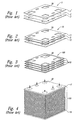
- Figures 1-4 collectively illustrate typical designs of a conventional MEA 5, electrochemical cell 10 comprising a PEM layer 2, and a stack 100 of such cells.
- Each cell 10 comprises a membrane electrode assembly ("MEA") 5 such as that illustrated in an exploded view in Figure 1.
- MEA 5 comprises an ion exchange membrane layer 2 interposed between first and second electrode layers 1 and 3, respectively, which are typically porous and electrically conductive, and each of which comprises an electrocatalyst at its interface with the ion exchange membrane layer 2 for promoting the desired electrochemical reaction.
- the electrocatalyst generally defines the electrochemically active area of the cell.
- the MEA 5 is typically consolidated as a bonded laminated assembly.
- an MEA 5 is interposed between first and second cell separator plates 11 and 12, respectively, which are typically fluid impermeable and electrically conductive.
- the cell separator plates 11, 12 are typically manufactured from non-metals, such as graphite; from metals, such as certain grades of steel or surface treated metals; or from electrically conductive plastic composite materials.
- Fluid flow spaces such as passages or chambers, are provided between the cell separator plates 11, 12 and the adjacent electrode layers 1, 3 to facilitate access of reactants to the electrode layers and removal of products.
- Such spaces may, for example, be provided by and the porous structure of the corresponding electrode layers 1, 3.
- More commonly channels are formed in the adjoining faces of the cell separator plates 11, 12, the electrode layers 1, 3, or both.
- Cell separator plates 11, 12 comprising such channels are commonly referred to as fluid flow field plates.
- Resilient gaskets or seals are typically provided around the perimeter of the flow fields between the faces of the MEA 5 and each of the cell separator plates 11, 12 to prevent leakage of fluid reactant and product streams.
- Electrochemical cells 10 with ion exchange membrane layers 2 are advantageously stacked to form a stack 100 (see Figure 4) comprising a plurality of cells disposed between first and second end plates 17, 18.
- a compression mechanism is typically employed to hold the cells 10 tightly together, to maintain good electrical contact between components, and to compress the seals.
- each cell 10 comprises a pair of cell separator plates 11, 12, and an MEA 5 interposed therebetween.
- An alternative configuration has a single separator plate or "bipolar plate" interposed between pairs of MEAs 5, contacting the cathode of one cell and the anode of the adjacent cell (except for the end cells).
- the stack 100 may comprise cooling layers interposed between every few cells 10 of the stack, or between each adjacent pair of cells.
- the cooling layers may be formed within the cell separator plates, for example, or they may comprise channels in bipolar plates used in the stack. Cooling layers of the latter type are disclosed in commonly assigned U.S. Pat. No. 5,230,966.
- the illustrated cell elements have openings 30 formed therein which, in the stacked assembly, align to form fluid manifolds for supply and exhaust of reactants and products and, if cooling spaces are provided, for a cooling medium.
- resilient gaskets or seals are typically provided between the faces of the MEA 5 and each of the cell separator plates 11, 12 around the perimeter of these fluid manifold openings 30 to prevent leakage and intermixing of fluid streams in the operating stack 100.
- the present invention relates to apparatus, systems and methods for use in bonding one element of an electrochemical cell stack to another element in the stack and/or for sealing portions of the stack, such as the perimeter of a manifold opening in a cell separator plate.
- the inventive method comprises providing a sealing surface on a first element of the stack with a complex groove having a raised portion and a depressed portion. Both the raised portion and the depressed portion lie below the plane of the sealing surface, but the depressed portion is further from the plane than the raised portion.
- the method then comprises depositing a bead of adhesive on the raised portion, such as by screen printing. When deposited, the bead projects above the plane of the sealing surface.
- the method then comprises abutting a second element of the stack against the first element. When the first and second elements of the stack are abutted, the adhesive is displaced in part from the raised portion of complex groove, and a portion of the bead of adhesive is received within the depressed portion of the groove.
- the method comprises providing a complex groove having a single raised portion positioned between two depressed portions.
- the raised portion is again configured to receive the bead of adhesive.
- a portion of the bead of adhesive is displaced into each of the two depressed portions.
- the present invention is also directed toward an electrochemical cell comprising a membrane electrode assembly positioned between first and second bodies, such as cell separator plates.
- the second body has a sealing groove with a complex cross-sectional shape.
- the sealing groove has a shallow portion that is wide enough to receive the volume of adhesive, and a deep portion configured to receive a portion of the adhesive that is displaced during assembly.
- the shallow portion of the sealing groove is curved to increase the strength of the bond between the first body and the second body.
- the curved shallow portion of the sealing groove is still wide enough to receive the bead of adhesive. Upon assembly, however, the bead is displaced along the entire width of the curved shallow portion. As a result, the bond between the first and second bodies is strengthened to better resist tension and shear.
- the present invention is generally directed toward methods, systems and apparatus for use in electrochemical cells, such as fuel cells.
- Embodiments of the present invention may allow portions of the fuel cell to be sealed while providing a stronger bond between the respective portions of the cell.
- Many specific details of certain embodiments of the invention are set forth in the following description and in Figures 5-15 to provide a thorough understanding of such embodiments.
- One skilled in the art, however, will understand that the present invention may have additional embodiments, or may be practiced without several of the details described in the following description.
- FIGS 5-7 illustrate a cell separator plate 110 and a screen mask 112 being used to apply an adhesive 114 to the cell separator plate prior to assembly of an electrochemical cell or cell stack.
- the cell separator plate 110 comprises a number of flow channels 116 for ultimately channeling coolant, fuel or oxidant to a membrane electrode assembly (not shown) or an adjacent cell separator plate.
- the cell separator plate 110 also has a sealing groove 118 used to bond the cell separator plate to an adjacent element in the cell or cell stack, and/or to seal a portion of the cell from other portions of the cell, from other portions of the stack, or from the external environment.
- the sealing groove 118 incorporates a raised central portion 120 and a pair of opposing depressed portions 122.
- the raised central portion is sufficiently wide to receive and retain a bead of adhesive, as discussed below.
- the screen mask 112 of the illustrated embodiment can be fabricated from screen 124 and mask layers 125.
- Screen 124 may comprise a stainless steel or polymer mesh with a 71% open area, although it is appreciated that other materials or porosities would be interchangable, as understood in the art. Similarly, more or fewer mask layers can be used without departing from the spirit of the invention.
- Screen mask 112 has one or more masked portions 126 and an open portion 128. The open portions 128 are aligned with the raised central portion 120 of the sealing groove 118. Applicant understands that a single screen can also be used, as generally understood in the art.
- a mass of adhesive 114 is positioned against the screen mask 112, and a squeegee 130 is positioned against the adhesive and moving the adhesive along the screen mask.
- the illustrated adhesive is an epoxy. Applicant appreciates that many other adhesives may also work, as generally understood in the art.
- the squeegee 130 has moved the adhesive 114 past the open portion 128 of the screen mask 112, and a portion of the adhesive 114 has filled the open portion of the screen mask.
- a two-squeegee process may be employed, wherein the first squeegee places the adhesive onto the screen mask and the second squeegee pushes the adhesive into the open portions thereof.
- the adhesive 114 within the open portion 128 of the screen mask 112 may contact the raised central portion 120 of the sealing groove 118.
- the adhesive 114 remains on the raised central portion 120.
- the bead of adhesive 114 ranges from 1.3-1.5 mm (0.050-0.060 inches) wide, although this width, as well as the corresponding width of the raised central portion 120, can vary.
- the above-described screen printing process can be used to apply a bead of adhesive to a cell separator plate or other elements of an electrochemical cell or cell stack.
- the cell separator plate 110 carrying the adhesive 114 can subsequently be bonded to another separate cell separator plate, a membrane electrode assembly, an end plate or any other element in the electrochemical cell or cell stack assembly.
- cell separator plates may be bonded together to form coolant channels at their interface.
- the bead of adhesive could be applied to the mating surface of the element to be bonded, such that the raised central portion 120 of the sealing groove 118 receives the bead of adhesive as the elements are brought into contact.
- the bead of adhesive can be applied through any other means known in the art, such as via an automated nozzle or other system.
- the sealing groove 118 can circumscribe a manifold hole, such as a hole through which air, fuel or cooling fluid flows, or can circumscribe a flow field or a membrane electrode assembly.
- a manifold hole such as a hole through which air, fuel or cooling fluid flows
- a flow field or a membrane electrode assembly can circumscribe a flow field or a membrane electrode assembly.
- Figure 8 illustrates a cell separator plate 210 and an electrode 211 from a membrane electrode assembly, according to another embodiment of the present invention.
- the raised central portion 220 of the sealing groove 218 has a convex cross-sectional shape.
- the raised central portion 220 is sufficiently wide to support the entire bead of adhesive 214.
- the adhesive 214 is distributed along the entire raised central portion 220, and extends into the opposing depressed portions 222.
- the size of the bead of adhesive 214 is preselected such that the depressed portions 222 are partially filled with adhesive upon assembly.
- the bond between the adhesive and the raised central portion resists separation of the plates 210, 211 in both the axial direction A and the lateral direction L.
- the bond between the cell separator plates 210, 211 is strengthened not only in an axial direction A but also in a lateral direction L, as well as along all positive and negative vector combinations thereof.
- Embodiments of the present invention have numerous advantages over the prior art.
- the raised central portion of the sealing groove places the adhesive closer to the mating object, increasing the likelihood of a successful bond.
- the raised central portion also allows for the use of a smaller bead of adhesive. Using less adhesive reduces the risk of unwanted overflow, wherein adhesive between the mating surfaces prevents perfect mating.
- two depressed portions are positioned adjacent the raised central portion, one on each side thereof, it is highly unlikely that adhesive will leak from the sealing groove and interfere with the mating surfaces.
- a known quantity of adhesive is used that fills only a portion of each depressed groove. As a result, even with a margin of error, there is an available volume remaining in which adhesive can be displaced before it contacts the mating surface.
- the contours on the raised central portion can increase the strength of the bond between the mating surfaces.
- FIGs 10-15 illustrate some of the many variations that can be made to the sealing groove as understood by the inventors. Many of these embodiments illustrate small changes. The inventors realize, however, that these small changes can be combined in many different ways to form even more variations. The inventors also realize that other modifications can be made without deviating from the spirit of the invention.
- Figure 10 illustrates a sealing groove 318 according to another embodiment of the present invention.
- the raised central portion 320 has an upper surface 321 that has been treated to increase the surface's roughness.
- the upper surface 321 has an anchor pattern that further increases the bond between the adhesive and the raised central portion 320 of the sealing groove 318.
- the sealing groove 318 may have an outer width W that ranges from 1.0-2.0 mm (0.040-0.080 inches), with the illustrated embodiment measuring 1.5 mm (0.060 inches).
- the raised central portion may have an inner width w that measures between 0.25-1.3 mm (0.010-0.050 inches), with the illustrated embodiment measuring 1.0 mm (0.040 inches).
- the raised central portion may have a depth d below a mating surface 323 of the cell separator plate 310 measuring approximately 25-130 ⁇ m (0.001-0.005 inches), with the illustrated embodiment measuring 50 ⁇ m (0.002 inches).
- the depressed portions 322 may have a depth D below the mating surface 323 measuring approximately 130-630 ⁇ m (0.005-0.025 inches), with the illustrated embodiment measuring 200 ⁇ m (0.008 inches).
- FIGS 11-14 illustrate four variations of sealing grooves 418, 518, 618, and 718, respectively, according to alternate embodiments of the present invention. They collectively illustrate that the sealing groove can have rounded edges, beveled edges, concave surfaces and triangular grooves, in addition to the other features previously illustrated.
- Figure 15 illustrates a sealing groove 818 according to yet another embodiment of the present invention.
- the sealing groove abuts an edge surface 819 of the electrochemical cell. Consequently, the depressed portion 822 closest to the edge surface 819 does not have an outer wall, but instead opens to the exterior environment. Adhesive positioned on the central raised finger 820 nonetheless is displaced into both of the depressed portions 822, as with the prior embodiments.
Applications Claiming Priority (2)
| Application Number | Priority Date | Filing Date | Title |
|---|---|---|---|
| US09/888,074 US6777127B2 (en) | 2001-06-22 | 2001-06-22 | Systems, apparatus and methods for bonding and/or sealing electrochemical cell elements and assemblies |
| US888074 | 2001-06-22 |
Publications (3)
| Publication Number | Publication Date |
|---|---|
| EP1271678A2 true EP1271678A2 (de) | 2003-01-02 |
| EP1271678A3 EP1271678A3 (de) | 2007-03-07 |
| EP1271678B1 EP1271678B1 (de) | 2012-12-05 |
Family
ID=25392470
Family Applications (1)
| Application Number | Title | Priority Date | Filing Date |
|---|---|---|---|
| EP02013593A Expired - Lifetime EP1271678B1 (de) | 2001-06-22 | 2002-06-20 | Systeme, Vorrichtungen und Verfahren zum Verbinden und/oder Abdichten elektrochemischer Zellenelementen und Zellenanlagen |
Country Status (3)
| Country | Link |
|---|---|
| US (1) | US6777127B2 (de) |
| EP (1) | EP1271678B1 (de) |
| CA (1) | CA2390949C (de) |
Cited By (3)
| Publication number | Priority date | Publication date | Assignee | Title |
|---|---|---|---|---|
| FR2932612A1 (fr) * | 2008-06-11 | 2009-12-18 | Helion | Plaque separatrice a double gorge pour pile a combustible |
| US7732082B2 (en) | 2004-04-26 | 2010-06-08 | Toyota Jidosha Kabushiki Kaisha | Fuel cell module |
| CN101335336B (zh) * | 2007-06-26 | 2013-08-07 | 现代自动车株式会社 | 燃料电池隔板的密封结构 |
Families Citing this family (24)
| Publication number | Priority date | Publication date | Assignee | Title |
|---|---|---|---|---|
| EP1416554B1 (de) * | 2001-07-06 | 2010-06-23 | Honda Giken Kogyo Kabushiki Kaisha | Verfahren zum beschichten eines dichtmaterials auf einen brennstoffzellenseparator |
| CA2451111C (en) * | 2001-07-11 | 2010-09-07 | Akiyoshi Machida | Method of coating fuel cell separator with seal material |
| US6761991B2 (en) * | 2001-10-16 | 2004-07-13 | Dow Corning Corporation | Seals for fuel cells and fuel cell stacks |
| US20030082430A1 (en) * | 2001-10-25 | 2003-05-01 | Daisuke Suzuki | Fuel cell gasket assembly and method of making |
| DE10216306B4 (de) * | 2002-04-14 | 2008-06-12 | Sgl Carbon Ag | Verfahren zur Herstellung einer Kontaktplatte für eine elektrochemische Zelle sowie deren Verwendungen |
| JP3951841B2 (ja) * | 2002-07-19 | 2007-08-01 | トヨタ自動車株式会社 | 燃料電池のシール構造とその製造方法 |
| US8007949B2 (en) * | 2002-10-08 | 2011-08-30 | Bhaskar Sompalli | Edge-protected catalyst-coated diffusion media and membrane electrode assemblies |
| US7556660B2 (en) | 2003-06-11 | 2009-07-07 | James Kevin Shurtleff | Apparatus and system for promoting a substantially complete reaction of an anhydrous hydride reactant |
| JP5038586B2 (ja) * | 2004-04-30 | 2012-10-03 | トヨタ自動車株式会社 | 燃料電池のセパレータ、セパレータの接合方法、燃料電池 |
| DE112006002142B4 (de) * | 2005-08-12 | 2021-02-11 | GM Global Technology Operations LLC (n. d. Ges. d. Staates Delaware) | Verfahren zum Herstellen einer Brennstoffzellenkomponente unter Verwendung einer leicht zu entfernenden Maskierung |
| US7648786B2 (en) | 2006-07-27 | 2010-01-19 | Trulite, Inc | System for generating electricity from a chemical hydride |
| US7651542B2 (en) | 2006-07-27 | 2010-01-26 | Thulite, Inc | System for generating hydrogen from a chemical hydride |
| US8221930B2 (en) * | 2006-08-23 | 2012-07-17 | Daimler Ag | Bipolar separators with improved fluid distribution |
| US20080050639A1 (en) * | 2006-08-23 | 2008-02-28 | Michael Medina | Bipolar flow field plate assembly and method of making the same |
| KR100820508B1 (ko) | 2007-03-23 | 2008-04-11 | 지에스칼텍스 주식회사 | 연료전지 스택 실링구조 |
| US8357214B2 (en) | 2007-04-26 | 2013-01-22 | Trulite, Inc. | Apparatus, system, and method for generating a gas from solid reactant pouches |
| US8364287B2 (en) | 2007-07-25 | 2013-01-29 | Trulite, Inc. | Apparatus, system, and method to manage the generation and use of hybrid electric power |
| WO2009048991A1 (en) * | 2007-10-08 | 2009-04-16 | Ames Rubber Corporation | Composite multilayer seal for pem fuel cell applications and method for constructing the same |
| JP5615875B2 (ja) * | 2012-01-16 | 2014-10-29 | 本田技研工業株式会社 | 燃料電池用樹脂枠付き電解質膜・電極構造体 |
| JP6118225B2 (ja) * | 2013-10-09 | 2017-04-19 | 本田技研工業株式会社 | 燃料電池用樹脂枠付き電解質膜・電極構造体 |
| JP6403541B2 (ja) * | 2014-10-31 | 2018-10-10 | パナソニック株式会社 | セパレータ−シール部材接合体及びその製造方法 |
| JP6263214B2 (ja) * | 2016-03-09 | 2018-01-17 | 本田技研工業株式会社 | 燃料電池用樹脂枠付き段差mea |
| DE102021204821A1 (de) | 2021-05-12 | 2022-11-17 | Cellcentric Gmbh & Co. Kg | Separatorplatte |
| DE102021119029A1 (de) | 2021-07-22 | 2023-01-26 | Vitesco Technologies GmbH | Metallische Bipolarplatte für eine Brennstoffzelle sowie Verfahren zur Herstellung einer derartigen Bipolarplatte |
Family Cites Families (33)
| Publication number | Priority date | Publication date | Assignee | Title |
|---|---|---|---|---|
| DE1964811A1 (de) | 1969-12-24 | 1971-07-01 | Siemens Ag | Brennstoffzellenbatterie |
| US4397917A (en) | 1982-01-11 | 1983-08-09 | Energy Research Corporation | Fuel cell pack with internal connection of fuel cells |
| US4505992A (en) | 1983-04-11 | 1985-03-19 | Engelhard Corporation | Integral gas seal for fuel cell gas distribution assemblies and method of fabrication |
| US4732637A (en) | 1983-04-11 | 1988-03-22 | Engelhard Corporation | Method of fabricating an integral gas seal for fuel cell gas distribution assemblies |
| JPS60200468A (ja) | 1984-03-23 | 1985-10-09 | Hitachi Ltd | 燃料電池 |
| US4755429A (en) | 1986-11-03 | 1988-07-05 | International Fuel Cells Corporation | Composite graphite separator plate for fuel cell stack |
| US4756981A (en) | 1986-12-29 | 1988-07-12 | International Fuel Cells | Seal structure for an electrochemical cell |
| EP0330124A3 (de) | 1988-02-24 | 1991-06-12 | Toray Industries, Inc. | Elektroleitendes integriertes Substrat und Verfahren zu seiner Herstellung |
| US4786568A (en) | 1988-03-01 | 1988-11-22 | International Fuel Cells Corporation | Electrode substrate with integral edge seal and method of forming the same |
| US5176966A (en) | 1990-11-19 | 1993-01-05 | Ballard Power Systems Inc. | Fuel cell membrane electrode and seal assembly |
| JPH04319261A (ja) * | 1991-04-18 | 1992-11-10 | Tokai Carbon Co Ltd | 燃料電池用炭素質複合基板の接合方法 |
| US5230966A (en) | 1991-09-26 | 1993-07-27 | Ballard Power Systems Inc. | Coolant flow field plate for electrochemical fuel cells |
| US5284718A (en) | 1991-09-27 | 1994-02-08 | Ballard Power Systems Inc. | Fuel cell membrane electrode and seal assembly |
| US5264299A (en) | 1991-12-26 | 1993-11-23 | International Fuel Cells Corporation | Proton exchange membrane fuel cell support plate and an assembly including the same |
| WO1993013566A1 (en) | 1991-12-26 | 1993-07-08 | International Fuel Cells, Inc. | Plate-shaped fuel cell component and a method of making the same |
| US5187025A (en) | 1992-02-03 | 1993-02-16 | Analytic Power Corp. | Unitized fuel cell structure |
| US5350643A (en) | 1992-06-02 | 1994-09-27 | Hitachi, Ltd. | Solid polymer electrolyte type fuel cell |
| EP0604683B1 (de) | 1992-12-31 | 1999-05-12 | Ballard Power Systems Inc. | Membranelektrodenzusammenbau und Abdichtung für Brennstoffzellen |
| DE4309976A1 (de) | 1993-03-26 | 1994-09-29 | Daimler Benz Ag | Elektrochemische Mehrzellenbatterie |
| DE4314745C1 (de) | 1993-05-04 | 1994-12-08 | Fraunhofer Ges Forschung | Brennstoffzelle |
| JPH0724917A (ja) | 1993-07-08 | 1995-01-27 | Fujipura Seiko:Kk | 高周波誘導加熱融着接合用熱可塑性合成樹脂管 |
| US5336274A (en) | 1993-07-08 | 1994-08-09 | Regents Of The University Of California | Method for forming a cell separator for use in bipolar-stack energy storage devices |
| JPH07235314A (ja) | 1994-02-21 | 1995-09-05 | Toyota Motor Corp | 固体高分子型燃料電池の単電池およびその製造方法 |
| DE4442285C1 (de) | 1994-11-28 | 1996-02-08 | Siemens Ag | Brennstoffzellen und daraus bestehende Brennstoffzellenbatterien |
| JPH08323980A (ja) | 1995-05-30 | 1996-12-10 | Oki Data:Kk | インクジェットプリンタにおける印字ヘッドの製造方法 |
| US5807606A (en) | 1995-08-24 | 1998-09-15 | Mpm Corporation | Applying adhesive to substrates |
| DE19542475C2 (de) | 1995-11-15 | 1999-10-28 | Ballard Power Systems | Polymerelektrolytmembran-Brennstoffzelle sowie Verfahren zur Herstellung einer Verteilerplatte für eine solche Zelle |
| US5858569A (en) | 1997-03-21 | 1999-01-12 | Plug Power L.L.C. | Low cost fuel cell stack design |
| DE19713250C2 (de) * | 1997-03-29 | 2002-04-18 | Ballard Power Systems | Elektrochemischer Energiewandler mit Polymerelektrolytmembran |
| AU8329398A (en) | 1997-07-16 | 1999-02-10 | Ballard Power Systems Inc. | Resilient seal for membrane electrode assembly (mea) in an electrochemical fuel cell and method of making same |
| JP2000168040A (ja) | 1998-12-04 | 2000-06-20 | Minami Kk | スクリーン印刷機 |
| JP3951484B2 (ja) * | 1998-12-16 | 2007-08-01 | トヨタ自動車株式会社 | 燃料電池 |
| WO2000054352A1 (en) * | 1999-03-10 | 2000-09-14 | Flexfab Horizons International, Inc. | Fuel cell gasket assembly and method of assembling fuel cells |
-
2001
- 2001-06-22 US US09/888,074 patent/US6777127B2/en not_active Expired - Lifetime
-
2002
- 2002-06-19 CA CA2390949A patent/CA2390949C/en not_active Expired - Lifetime
- 2002-06-20 EP EP02013593A patent/EP1271678B1/de not_active Expired - Lifetime
Non-Patent Citations (1)
| Title |
|---|
| None |
Cited By (4)
| Publication number | Priority date | Publication date | Assignee | Title |
|---|---|---|---|---|
| US7732082B2 (en) | 2004-04-26 | 2010-06-08 | Toyota Jidosha Kabushiki Kaisha | Fuel cell module |
| DE112005000938B4 (de) | 2004-04-26 | 2022-03-24 | Toyota Jidosha Kabushiki Kaisha | Brennstoffzellenmodul mit verklebten Separatorkomponenten |
| CN101335336B (zh) * | 2007-06-26 | 2013-08-07 | 现代自动车株式会社 | 燃料电池隔板的密封结构 |
| FR2932612A1 (fr) * | 2008-06-11 | 2009-12-18 | Helion | Plaque separatrice a double gorge pour pile a combustible |
Also Published As
| Publication number | Publication date |
|---|---|
| US20020197519A1 (en) | 2002-12-26 |
| EP1271678B1 (de) | 2012-12-05 |
| CA2390949C (en) | 2011-06-07 |
| EP1271678A3 (de) | 2007-03-07 |
| CA2390949A1 (en) | 2002-12-22 |
| US6777127B2 (en) | 2004-08-17 |
Similar Documents
| Publication | Publication Date | Title |
|---|---|---|
| US6777127B2 (en) | Systems, apparatus and methods for bonding and/or sealing electrochemical cell elements and assemblies | |
| US6261711B1 (en) | Sealing system for fuel cells | |
| CA2243355C (en) | Electrochemical fuel cell stack with improved reactant manifolding and sealing | |
| CA2866234C (en) | Fuel cell with resin frame having buffer and connection channel | |
| US20010019792A1 (en) | Electrochemical fuel cell stack with improved reactant manifolding and sealing | |
| US7951481B2 (en) | Separator and cell using the same for use in solid polymer electrolyte fuel cell | |
| US7081316B2 (en) | Bipolar plate assembly having transverse legs | |
| JPH08222237A (ja) | 燃料電池用セパレータ | |
| EP1630892A2 (de) | Separator sowie damit versehene Festpolymerelektrolyt-Brennstoffzelle | |
| EP1622217B1 (de) | Festpolymerelektrolyt-Brennstoffzelle | |
| US20070020504A1 (en) | Fuel cell | |
| CA2594530C (en) | Fuel cell separator | |
| US7186476B2 (en) | One piece bipolar plate with spring seals | |
| US11171341B2 (en) | Fuel cell and method of manufacturing fuel cell | |
| EP1416556B1 (de) | Separatorplatte für Polymerelektrolytbrennstoffzelle und diese verwendende Polymerelektrolytbrennstoffzelle | |
| EP2054965B1 (de) | Bipolare separatoren mit verbesserter flüssigkeitsverteilung | |
| US7824817B2 (en) | Fuel cell | |
| JP2005108506A (ja) | 燃料電池 | |
| US20040159543A1 (en) | Electrochemical cell plate with integral seals | |
| JP2004335179A (ja) | 燃料電池 | |
| US20110262831A1 (en) | Formed plate assembly for pem fuel cell | |
| US20060127736A1 (en) | Fuel cell seal with integral bridge | |
| KR100546016B1 (ko) | 연료전지용 전류집전체와 그 제조방법, 그리고 이를구비한 연료전지 | |
| JP2004039385A (ja) | 燃料電池 | |
| US7597984B2 (en) | Fuel cell bipolar plates with multiple active areas separated by non-conductive frame header |
Legal Events
| Date | Code | Title | Description |
|---|---|---|---|
| PUAI | Public reference made under article 153(3) epc to a published international application that has entered the european phase |
Free format text: ORIGINAL CODE: 0009012 |
|
| AK | Designated contracting states |
Kind code of ref document: A2 Designated state(s): AT BE CH CY DE DK ES FI FR GB GR IE IT LI LU MC NL PT SE TR |
|
| AX | Request for extension of the european patent |
Free format text: AL;LT;LV;MK;RO;SI |
|
| RAP1 | Party data changed (applicant data changed or rights of an application transferred) |
Owner name: BALLARD POWER SYSTEMS INC. |
|
| PUAL | Search report despatched |
Free format text: ORIGINAL CODE: 0009013 |
|
| AK | Designated contracting states |
Kind code of ref document: A3 Designated state(s): AT BE CH CY DE DK ES FI FR GB GR IE IT LI LU MC NL PT SE TR |
|
| AX | Request for extension of the european patent |
Extension state: AL LT LV MK RO SI |
|
| 17P | Request for examination filed |
Effective date: 20070419 |
|
| AKX | Designation fees paid |
Designated state(s): AT BE CH CY DE DK ES FI FR GB GR IE IT LI LU MC NL PT SE TR |
|
| 17Q | First examination report despatched |
Effective date: 20071107 |
|
| RAP1 | Party data changed (applicant data changed or rights of an application transferred) |
Owner name: BDF IP HOLDINGS LTD. |
|
| RIC1 | Information provided on ipc code assigned before grant |
Ipc: C25B 9/10 20060101AFI20120329BHEP Ipc: C25B 9/18 20060101ALI20120329BHEP |
|
| RIC1 | Information provided on ipc code assigned before grant |
Ipc: H01M 8/02 20060101AFI20120330BHEP |
|
| GRAP | Despatch of communication of intention to grant a patent |
Free format text: ORIGINAL CODE: EPIDOSNIGR1 |
|
| GRAS | Grant fee paid |
Free format text: ORIGINAL CODE: EPIDOSNIGR3 |
|
| RAP1 | Party data changed (applicant data changed or rights of an application transferred) |
Owner name: DAIMLER AG Owner name: FORD MOTOR COMPANY |
|
| GRAA | (expected) grant |
Free format text: ORIGINAL CODE: 0009210 |
|
| AK | Designated contracting states |
Kind code of ref document: B1 Designated state(s): AT BE CH CY DE DK ES FI FR GB GR IE IT LI LU MC NL PT SE TR |
|
| REG | Reference to a national code |
Ref country code: GB Ref legal event code: FG4D |
|
| REG | Reference to a national code |
Ref country code: CH Ref legal event code: EP |
|
| REG | Reference to a national code |
Ref country code: AT Ref legal event code: REF Ref document number: 587690 Country of ref document: AT Kind code of ref document: T Effective date: 20121215 |
|
| REG | Reference to a national code |
Ref country code: IE Ref legal event code: FG4D |
|
| REG | Reference to a national code |
Ref country code: DE Ref legal event code: R096 Ref document number: 60244147 Country of ref document: DE Effective date: 20130131 |
|
| REG | Reference to a national code |
Ref country code: AT Ref legal event code: MK05 Ref document number: 587690 Country of ref document: AT Kind code of ref document: T Effective date: 20121205 |
|
| PG25 | Lapsed in a contracting state [announced via postgrant information from national office to epo] |
Ref country code: SE Free format text: LAPSE BECAUSE OF FAILURE TO SUBMIT A TRANSLATION OF THE DESCRIPTION OR TO PAY THE FEE WITHIN THE PRESCRIBED TIME-LIMIT Effective date: 20121205 Ref country code: ES Free format text: LAPSE BECAUSE OF FAILURE TO SUBMIT A TRANSLATION OF THE DESCRIPTION OR TO PAY THE FEE WITHIN THE PRESCRIBED TIME-LIMIT Effective date: 20130316 Ref country code: FI Free format text: LAPSE BECAUSE OF FAILURE TO SUBMIT A TRANSLATION OF THE DESCRIPTION OR TO PAY THE FEE WITHIN THE PRESCRIBED TIME-LIMIT Effective date: 20121205 |
|
| REG | Reference to a national code |
Ref country code: NL Ref legal event code: VDEP Effective date: 20121205 |
|
| PG25 | Lapsed in a contracting state [announced via postgrant information from national office to epo] |
Ref country code: GR Free format text: LAPSE BECAUSE OF FAILURE TO SUBMIT A TRANSLATION OF THE DESCRIPTION OR TO PAY THE FEE WITHIN THE PRESCRIBED TIME-LIMIT Effective date: 20130306 Ref country code: CY Free format text: LAPSE BECAUSE OF FAILURE TO SUBMIT A TRANSLATION OF THE DESCRIPTION OR TO PAY THE FEE WITHIN THE PRESCRIBED TIME-LIMIT Effective date: 20121205 |
|
| PG25 | Lapsed in a contracting state [announced via postgrant information from national office to epo] |
Ref country code: AT Free format text: LAPSE BECAUSE OF FAILURE TO SUBMIT A TRANSLATION OF THE DESCRIPTION OR TO PAY THE FEE WITHIN THE PRESCRIBED TIME-LIMIT Effective date: 20121205 |
|
| PG25 | Lapsed in a contracting state [announced via postgrant information from national office to epo] |
Ref country code: BE Free format text: LAPSE BECAUSE OF FAILURE TO SUBMIT A TRANSLATION OF THE DESCRIPTION OR TO PAY THE FEE WITHIN THE PRESCRIBED TIME-LIMIT Effective date: 20121205 |
|
| PG25 | Lapsed in a contracting state [announced via postgrant information from national office to epo] |
Ref country code: NL Free format text: LAPSE BECAUSE OF FAILURE TO SUBMIT A TRANSLATION OF THE DESCRIPTION OR TO PAY THE FEE WITHIN THE PRESCRIBED TIME-LIMIT Effective date: 20121205 Ref country code: PT Free format text: LAPSE BECAUSE OF FAILURE TO SUBMIT A TRANSLATION OF THE DESCRIPTION OR TO PAY THE FEE WITHIN THE PRESCRIBED TIME-LIMIT Effective date: 20130405 |
|
| PLBE | No opposition filed within time limit |
Free format text: ORIGINAL CODE: 0009261 |
|
| STAA | Information on the status of an ep patent application or granted ep patent |
Free format text: STATUS: NO OPPOSITION FILED WITHIN TIME LIMIT |
|
| PG25 | Lapsed in a contracting state [announced via postgrant information from national office to epo] |
Ref country code: DK Free format text: LAPSE BECAUSE OF FAILURE TO SUBMIT A TRANSLATION OF THE DESCRIPTION OR TO PAY THE FEE WITHIN THE PRESCRIBED TIME-LIMIT Effective date: 20121205 |
|
| 26N | No opposition filed |
Effective date: 20130906 |
|
| PG25 | Lapsed in a contracting state [announced via postgrant information from national office to epo] |
Ref country code: IT Free format text: LAPSE BECAUSE OF FAILURE TO SUBMIT A TRANSLATION OF THE DESCRIPTION OR TO PAY THE FEE WITHIN THE PRESCRIBED TIME-LIMIT Effective date: 20121205 |
|
| REG | Reference to a national code |
Ref country code: DE Ref legal event code: R097 Ref document number: 60244147 Country of ref document: DE Effective date: 20130906 |
|
| PG25 | Lapsed in a contracting state [announced via postgrant information from national office to epo] |
Ref country code: MC Free format text: LAPSE BECAUSE OF FAILURE TO SUBMIT A TRANSLATION OF THE DESCRIPTION OR TO PAY THE FEE WITHIN THE PRESCRIBED TIME-LIMIT Effective date: 20121205 |
|
| REG | Reference to a national code |
Ref country code: CH Ref legal event code: PL |
|
| REG | Reference to a national code |
Ref country code: IE Ref legal event code: MM4A |
|
| PG25 | Lapsed in a contracting state [announced via postgrant information from national office to epo] |
Ref country code: LI Free format text: LAPSE BECAUSE OF NON-PAYMENT OF DUE FEES Effective date: 20130630 Ref country code: CH Free format text: LAPSE BECAUSE OF NON-PAYMENT OF DUE FEES Effective date: 20130630 Ref country code: IE Free format text: LAPSE BECAUSE OF NON-PAYMENT OF DUE FEES Effective date: 20130620 |
|
| PG25 | Lapsed in a contracting state [announced via postgrant information from national office to epo] |
Ref country code: TR Free format text: LAPSE BECAUSE OF FAILURE TO SUBMIT A TRANSLATION OF THE DESCRIPTION OR TO PAY THE FEE WITHIN THE PRESCRIBED TIME-LIMIT Effective date: 20121205 |
|
| PG25 | Lapsed in a contracting state [announced via postgrant information from national office to epo] |
Ref country code: LU Free format text: LAPSE BECAUSE OF NON-PAYMENT OF DUE FEES Effective date: 20130620 |
|
| REG | Reference to a national code |
Ref country code: FR Ref legal event code: PLFP Year of fee payment: 15 |
|
| REG | Reference to a national code |
Ref country code: FR Ref legal event code: PLFP Year of fee payment: 16 |
|
| REG | Reference to a national code |
Ref country code: FR Ref legal event code: PLFP Year of fee payment: 17 |
|
| REG | Reference to a national code |
Ref country code: DE Ref legal event code: R081 Ref document number: 60244147 Country of ref document: DE Owner name: FORD MOTOR COMPANY, 48126 DEARBORN, US Free format text: FORMER OWNERS: DAIMLER AG, 70327 STUTTGART, DE; FORD MOTOR COMPANY, DEARBORN, MICH., US Ref country code: DE Ref legal event code: R081 Ref document number: 60244147 Country of ref document: DE Owner name: CELLCENTRIC GMBH & CO. KG, DE Free format text: FORMER OWNERS: DAIMLER AG, 70327 STUTTGART, DE; FORD MOTOR COMPANY, DEARBORN, MICH., US Ref country code: DE Ref legal event code: R081 Ref document number: 60244147 Country of ref document: DE Owner name: FORD MOTOR COMPANY, DEARBORN, US Free format text: FORMER OWNERS: DAIMLER AG, 70327 STUTTGART, DE; FORD MOTOR COMPANY, DEARBORN, MICH., US Ref country code: DE Ref legal event code: R081 Ref document number: 60244147 Country of ref document: DE Owner name: DAIMLER AG, DE Free format text: FORMER OWNERS: DAIMLER AG, 70327 STUTTGART, DE; FORD MOTOR COMPANY, DEARBORN, MICH., US Ref country code: DE Ref legal event code: R082 Ref document number: 60244147 Country of ref document: DE Representative=s name: JENSEN & SON, GB Ref country code: DE Ref legal event code: R082 Ref document number: 60244147 Country of ref document: DE Representative=s name: JENSENS IP LIMITED, IE |
|
| REG | Reference to a national code |
Ref country code: DE Ref legal event code: R082 Ref document number: 60244147 Country of ref document: DE Representative=s name: WALLINGER RICKER SCHLOTTER TOSTMANN PATENT- UN, DE Ref country code: DE Ref legal event code: R082 Ref document number: 60244147 Country of ref document: DE Representative=s name: JENSENS IP LIMITED, IE |
|
| PGFP | Annual fee paid to national office [announced via postgrant information from national office to epo] |
Ref country code: FR Payment date: 20210625 Year of fee payment: 20 |
|
| PGFP | Annual fee paid to national office [announced via postgrant information from national office to epo] |
Ref country code: GB Payment date: 20210625 Year of fee payment: 20 |
|
| REG | Reference to a national code |
Ref country code: DE Ref legal event code: R081 Ref document number: 60244147 Country of ref document: DE Owner name: FORD MOTOR COMPANY, 48126 DEARBORN, US Free format text: FORMER OWNERS: DAIMLER AG, STUTTGART, DE; FORD MOTOR COMPANY, DEARBORN, MICH., US Ref country code: DE Ref legal event code: R081 Ref document number: 60244147 Country of ref document: DE Owner name: CELLCENTRIC GMBH & CO. KG, DE Free format text: FORMER OWNERS: DAIMLER AG, STUTTGART, DE; FORD MOTOR COMPANY, DEARBORN, MICH., US Ref country code: DE Ref legal event code: R082 Ref document number: 60244147 Country of ref document: DE Representative=s name: WALLINGER RICKER SCHLOTTER TOSTMANN PATENT- UN, DE |
|
| PGFP | Annual fee paid to national office [announced via postgrant information from national office to epo] |
Ref country code: DE Payment date: 20210827 Year of fee payment: 20 |
|
| REG | Reference to a national code |
Ref country code: GB Ref legal event code: 732E Free format text: REGISTERED BETWEEN 20220120 AND 20220126 |
|
| REG | Reference to a national code |
Ref country code: DE Ref legal event code: R071 Ref document number: 60244147 Country of ref document: DE |
|
| REG | Reference to a national code |
Ref country code: GB Ref legal event code: PE20 Expiry date: 20220619 |
|
| PG25 | Lapsed in a contracting state [announced via postgrant information from national office to epo] |
Ref country code: GB Free format text: LAPSE BECAUSE OF EXPIRATION OF PROTECTION Effective date: 20220619 |