EP1271267A2 - Mechanische Uhr - Google Patents
Mechanische Uhr Download PDFInfo
- Publication number
- EP1271267A2 EP1271267A2 EP02013113A EP02013113A EP1271267A2 EP 1271267 A2 EP1271267 A2 EP 1271267A2 EP 02013113 A EP02013113 A EP 02013113A EP 02013113 A EP02013113 A EP 02013113A EP 1271267 A2 EP1271267 A2 EP 1271267A2
- Authority
- EP
- European Patent Office
- Prior art keywords
- tension spring
- pawl
- elevator
- spring
- housing
- Prior art date
- Legal status (The legal status is an assumption and is not a legal conclusion. Google has not performed a legal analysis and makes no representation as to the accuracy of the status listed.)
- Withdrawn
Links
- 238000004804 winding Methods 0.000 claims abstract description 18
- 244000027321 Lychnis chalcedonica Species 0.000 description 2
- 238000009434 installation Methods 0.000 description 2
- 238000010276 construction Methods 0.000 description 1
- 230000005021 gait Effects 0.000 description 1
- 230000003116 impacting effect Effects 0.000 description 1
Images

Classifications
-
- G—PHYSICS
- G04—HOROLOGY
- G04B—MECHANICALLY-DRIVEN CLOCKS OR WATCHES; MECHANICAL PARTS OF CLOCKS OR WATCHES IN GENERAL; TIME PIECES USING THE POSITION OF THE SUN, MOON OR STARS
- G04B33/00—Calibers
- G04B33/12—Calibers for extremely long running times
-
- G—PHYSICS
- G04—HOROLOGY
- G04B—MECHANICALLY-DRIVEN CLOCKS OR WATCHES; MECHANICAL PARTS OF CLOCKS OR WATCHES IN GENERAL; TIME PIECES USING THE POSITION OF THE SUN, MOON OR STARS
- G04B3/00—Normal winding of clockworks by hand or mechanically; Winding up several mainsprings or driving weights simultaneously
- G04B3/003—Normal winding of clockworks by hand or mechanically; Winding up several mainsprings or driving weights simultaneously by lever mechanism
-
- G—PHYSICS
- G04—HOROLOGY
- G04B—MECHANICALLY-DRIVEN CLOCKS OR WATCHES; MECHANICAL PARTS OF CLOCKS OR WATCHES IN GENERAL; TIME PIECES USING THE POSITION OF THE SUN, MOON OR STARS
- G04B3/00—Normal winding of clockworks by hand or mechanically; Winding up several mainsprings or driving weights simultaneously
- G04B3/06—Keys or the like with means preventing overwinding
Definitions
- the invention relates to a mechanical watch, in particular a wristwatch with manual winding.
- a mechanical watch is known from CH 28100, in which the movement of the watch in a lower part and an upper part is divided, the diameter the outer diameter of the plant and thus the inner diameter of the watch case, with the lower part completely is taken up by the spring housing, so that the outer diameter the mainspring essentially the inside diameter of the watch case equivalent.
- this watch has a separate barrel, which is in one housing is located above.
- the invention is therefore based on the object of a mechanical watch, in particular to propose a wristwatch with a significantly longer duration that is comparatively easy to wind up.
- a mechanical watch in particular a wristwatch, is thus provided, the housing of which comprises a lower part and an upper part, the diameter of which corresponds to the inside diameter of the watch case, the lower part forming the spring housing and being completely occupied by a tension spring, so that the outer diameter of the tension spring corresponds substantially to the inner diameter of the watch case, and wherein the upper part of the housing contains the mechanism for tensioning the tension spring (winding mechanism), wherein the elevator mechanism comprises an elevator lever which is connected at one end via an axis to the spring core of the tension spring and at the other end to an elevator ring, and comprises an upper and lower ratchet, wherein the upper ratchet consists of an upper pawl and an upper ratchet wheel, which can be brought into engagement with one another via an adjusting lever and an adjusting crown, the lower ratchet consists of a lower pawl and a lower ratchet wheel which are in engagement with each other, and the adjusting crown is adjustable, the upper pawl being in
- the elevator mechanism comprises an elevator lever (16) which is connected at one end via an axis (6) to the spring core (5) of the tension spring (4) and at its other end to an elevator ring (15), and an upper and lower one Ratchet, being the upper locking mechanism consists of an upper pawl (11) and an upper locking wheel (12), which can be brought into engagement with one another via an adjusting lever (13) and an adjusting crown (14), the lower ratchet consists of a lower pawl (17) and a lower ratchet wheel (18) which are in engagement with each other, and the adjusting crown (14) is adjustable, the upper pawl (11) being in engagement with the upper ratchet wheel (12) in a first setting position, so that the tension spring (4) can be tensioned by rotating the winding ring (15), and in a second position the upper pawl (11) with the upper ratchet (12) is disengaged so that the clock can run.
- the upper locking mechanism consists of an upper pawl (11) and an upper locking wheel (12), which can
- the axis (6) carries a drive wheel (7), which with additional wheels (9, 10) Drive of the clockwork is engaged.
- the upper part of the housing expediently contains the mechanism for tensioning the tension spring (elevator mechanism).
- the watch according to the invention uses the space available in a watch case much more effective.
- the entire lower area of the watch case will occupied by the tension spring, so that much larger springs than before can be used in the watch.
- This tension spring has one accordingly large innerspring, so that even without an additional intermediate lift Power output is achieved by the tension spring.
- the duration of the course is at least 40 days, that is almost thirty times that Duration of mechanical clocks common today. With the proposed construction however, a gait duration that exceeds 40 days can also be achieved.
- the lower subspace and the upper one Part of the housing separated by an intermediate floor.
- the axis is in the upper part of the room with gears, which are part of the elevator or drive mechanism are.
- the elevator mechanism comprises an elevator lever, which on its one end over the extended axis with the spring core of the tension spring and on its other end is connected to an elevator ring.
- an elevator lever which on its one end over the extended axis with the spring core of the tension spring and on its other end is connected to an elevator ring.
- the outer diameter of the winding ring is essentially the outer diameter of the watch case.
- the elevator mechanism further includes an upper and a lower one Lock, the upper lock consisting of an upper pawl and a upper ratchet wheel, which are connected to each other via an adjusting lever and an adjusting crown can be engaged.
- the upper ratchet should be above of the drive wheel on the axis.
- the lower ratchet exists from a lower pawl and a lower ratchet wheel, which together are engaged.
- the lower ratchet should be below the drive wheel be arranged on the axis.
- the crown is adjustable, which means that two positions can be achieved can.
- the upper pawl In the first position, the upper pawl is with the upper one Locking wheel engaged so that the tension spring is tensioned by turning the winding ring can be.
- This position is achieved by the crown of the housing edge is moved away, whereby the upper lever Pawl is brought into engagement with the upper ratchet.
- the Elevator ring (multiple) first by 90 ° clockwise and then moved 90 ° counterclockwise.
- the upper pawl is disengaged from the upper ratchet so that the watch can expire.
- the second setting position is reached by placing the setting crown in Moving towards the housing.
- the upper pawl disengaged from the upper ratchet wheel.
- the control lever is preferably designed as an angle lever. The upper and lower ratchet runs synchronously with the drive wheel when the clock is running.
- the clockwork is therefore not wound up by means of an elevator crown as before, since there is a very high number of revolutions for tensioning the tension spring the crown would be necessary. Rather, the tension spring by means of a Tensioned winding ring, which is connected to the spring core of the spring lever Tension spring is connected. Because of the size, which is essentially the outside diameter of the watch case, a large tension spring can also be used large spring core. The tension of the large tension spring can thus done in a simple manner so that the watch can be wound easily and effortlessly can be. Furthermore, due to the long running time of the watch, winding it up only required every 40 days or less.
- the spring core of the tension spring, the drive wheel and / or the are more expedient auxiliary wheels belonging to the drive mechanism of the watch have ball bearings.
- the auxiliary wheels are in contact with the via the drive wheel and the axle Spring core of the tension spring.
- the watch case has an outer diameter of 37 mm and an inner diameter of 33 mm.
- the inside diameter the housing is thus sufficiently large to be comparatively large Take up tension spring.
- the spring core of this tension spring preferably has one Diameter of 12 mm, so that the loss of power between the fully tensioned Tension spring and the barely tensioned tension spring is relatively low.
- a Maltese cross position can be built into the clock.
- the watch can also be equipped with an intermediate winding (remontoire) be, in which the tension spring at regular intervals a second, smaller Spring winds, which gives its power evenly to the clockwork. To this The accuracy of the clock is further increased in this way.
- the proposed clock allows a cycle time of up to 80 Days to.
- the lower part 2 takes the tension spring 4, in the center of which the spring core 5 of the tension spring 4 is located.
- the spring core 5 is connected to the drive wheel 7 via an extended axis 6, which is located in the upper part 3.
- the drive wheel 7 is located again in engagement with the auxiliary wheel 10, via which the clockwork is driven becomes.
- Fig. 2 the lower compartment 2 is shown, the tension spring 4 with spring core 5 records. It can be seen that the outer diameter of the tension spring 4 essentially corresponds to the inside diameter of the housing. This makes it possible to use a comparatively large tension spring, which moreover has a large spring core.
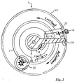
- the elevator mechanism for the tension spring 4 is located in the upper part of the room 3 (Fig. 3).
- the upper locking device comprises an upper pawl 11 which engages with an upper ratchet wheel 12 arranged on the axis 6 can.
- the pawl 11 is in contact with an actuating lever 13, which in turn is connected to the adjusting crown 14. As shown, the crown is from the Pulled out housing 1, the upper pawl 11 is engaged with the upper ratchet wheel 12. If in this position the elevator ring 15 (several times) each by a quarter turn clockwise and then is turned back, the tension spring 4 on the force acting on the winding ring 15, the elevator lever 16, which connects the elevator ring 15 to the axis 6, and the axis 6 acts on the spring core 5, drawn.
- the elevator ring 15 is turned completely to the left and snaps into a cam (not shown).
- the crown 14 is back in the case is pushed in, the upper pawl 11 passes through the adjusting lever 13 disengaged from the upper ratchet wheel 12 so that the drive wheel 7 and so the clock can run out.
- the lower locking device comprises a lower pawl 17 which is in engagement with a lower ratchet 18, which is on the axis 6 below the drive wheel 7 is arranged.
- the watch has a Maltese cross position (not shown) equipped.
Landscapes
- Physics & Mathematics (AREA)
- General Physics & Mathematics (AREA)
- Measurement Of Unknown Time Intervals (AREA)
- Electric Clocks (AREA)
Abstract
der Aufzugsmechanismus einen Aufzugshebel (16), der an seinem einen Ende über eine Achse (6) mit dem Federkern (5) der Zugfeder (4) und an seinem anderen Ende mit einem Aufzugsring (15) verbunden ist, und ein oberes und unteres Gesperr umfaßt, wobei
das obere Gesperr aus einer oberen Sperrklinke (11) und einem oberen Sperrad (12) besteht, die miteinander über einen Stellhebel (13) und eine Stellkrone (14) in Eingriff gebracht werden können,
das untere Gesperr aus einer unteren Sperrklinke (17) und einem unteren Sperrad (18) besteht, die miteinander in Eingriff stehen, und die Stellkrone (14) verstellbar ist, wobei in einer ersten Stellposition die obere Sperrklinke (11) mit dem oberen Sperrad (12) in Eingriff steht, so daß durch Drehen des Aufzugsringes (15) die Zugfeder (4) gespannt werden kann, und in einer zweiten Stellposition die obere Sperrklinke (11) mit dem oberen Sperrad (12) außer Eingriff ist, so daß die Uhr ablaufen kann, und wobei
die Achse (6) ein Antriebsrad (7) trägt, welches mit Beisatzrädern (9,10) zum Antrieb des Uhrwerkes in Eingriff steht.
Description
der Aufzugsmechanismus einen Aufzugshebel, der an seinem einen Ende über eine Achse mit dem Federkern der Zugfeder und an seinem anderen Ende mit einem Aufzugsring verbunden ist, und ein oberes und unteres Gesperr umfaßt, wobei
das obere Gesperr aus einer oberen Sperrklinke und einem oberen Sperrad besteht, die miteinander über einen Stellhebel und eine Stellkrone in Eingriff gebracht werden können,
das untere Gesperr aus einer unteren Sperrklinke und einem unteren Sperrad besteht, die miteinander in Eingriff stehen, und
die Stellkrone verstellbar ist, wobei in einer ersten Stellposition die obere Sperrklinke mit dem oberen Sperrad in Eingriff steht, so daß durch Drehen des Aufzugsringes die Zugfeder gespannt werden kann, und in einer zweiten Stellposition die obere Sperrklinke mit dem oberen Sperrad außer Eingriff ist, so daß die Uhr ablaufen kann, und wobei
die Achse ein Antriebsrad trägt, welches mit Beisatzrädern zum Antrieb des Uhrwerkes in Eingriff steht.
das obere Gesperr aus einer oberen Sperrklinke (11) und einem oberen Sperrad (12) besteht, die miteinander über einen Stellhebel (13) und eine Stellkrone (14) in Eingriff gebracht werden können,
das untere Gesperr aus einer unteren Sperrklinke (17) und einem unteren Sperrad (18) besteht, die miteinander in Eingriff stehen, und
die Stellkrone (14) verstellbar ist, wobei in einer ersten Stellposition die obere Sperrklinke (11) mit dem oberen Sperrad (12) in Eingriff steht, so daß durch Drehen des Aufzugsringes (15) die Zugfeder (4) gespannt werden kann, und in einer zweiten Stellposition die obere Sperrklinke (11) mit dem oberen Sperrad (12) außer Eingriff ist, so daß die Uhr ablaufen kann.
- 1
- Uhrgehäuse
- 2
- unterer Teilraum der Aufzugseinrichtung
- 3
- oberer Teilraum der Aufzugseinrichtung
- 4
- Zugfeder
- 5
- Federkern
- 6
- Achse
- 7
- Antriebsrad
- 8
- Zwischenboden
- 9
- Beisatzrad
- 10
- Beisatzrad
- 11
- obere Sperrklinke
- 12
- oberes Sperrad
- 13
- Stellhebel
- 14
- Stellkrone
- 15
- Aufzugsring
- 16
- Aufzugshebel
- 17
- untere Sperrklinke
- 18
- unteres Sperrad
Claims (7)
- Mechanische Uhr, insbesondere Armbanduhr, deren Gehäuse (1) einen unteren Teilraum (2) und einen oberen Teilraum (3) umfaßt, deren Durchmesser jeweils dem Innendurchmesser des Uhrgehäuses (1) entspricht, wobei der untere Teilraum (2) das Federgehäuse bildet und vollständig von einer Zugfeder (4) eingenommen ist, so daß der Außendurchmesser der Zugfeder (4) im wesentlichen dem Innendurchmesser des Uhrgehäuses (1) entspricht, und wobei der obere Teilraum (3) des Gehäuses (1) den Mechanismus zum Spannen der Zugfeder (4) (Aufzugsmechanismus) enthält, dadurch gekennzeichnet, daß
der Aufzugsmechanismus einen Aufzugshebel (16), der an seinem einen Ende über eine Achse (6) mit dem Federkern (5) der Zugfeder (4) und an seinem anderen Ende mit einem Aufzugsring (15) verbunden ist, und ein oberes und unteres Gesperr umfaßt, wobei
das obere Gesperr aus einer oberen Sperrklinke (11) und einem oberen Sperrad (12) besteht, die miteinander über einen Stellhebel (13) und eine Stellkrone (14) in Eingriff gebracht werden können,
das untere Gesperr aus einer unteren Sperrklinke (17) und einem unteren Sperrad (18) besteht, die miteinander in Eingriff stehen, und
die Stellkrone (14) verstellbar ist, wobei in einer ersten Stellposition die obere Sperrklinke (11) mit dem oberen Sperrad (12) in Eingriff steht, so daß durch Drehen des Aufzugsringes (15) die Zugfeder (4) gespannt werden kann, und in einer zweiten Stellposition die obere Sperrklinke (11) mit dem oberen Sperrad (12) außer Eingriff ist, so daß die Uhr ablaufen kann, und daß
die Achse (6) ein Antriebsrad (7) trägt, welches mit Beisatzrädern (9, 10) zum Antrieb des Uhrwerkes in Eingriff steht. - Mechanische Uhr nach Anspruch 1, dadurch gekennzeichnet, daß der untere Teilraum (2) und der obere Teilraum (3) des Gehäuses (1) durch einen Zwischenboden (8) getrennt sind.
- Mechanische Uhr nach einem der vorstehenden Ansprüche, dadurch gekennzeichnet, daß der Außendurchmesser des Aufzugsrings (15) im wesentlichen dem Außendurchmesser des Uhrgehäuses (1) entspricht.
- Mechanische Uhr nach einem der vorstehenden Ansprüche, dadurch gekennzeichnet, daß das obere Sperrad (12) oberhalb des Antriebsrades (7) auf der Achse (6) angeordnet ist.
- Mechanische Uhr nach einem der vorstehenden Ansprüche, dadurch gekennzeichnet, daß das untere Sperrad (18) unterhalb des Antriebsrades (7) auf der Achse (6) angeordnet ist.
- Mechanische Uhr nach einem der vorstehenden Ansprüche, dadurch gekennzeichnet, daß der Federkern (5) kugelgelagert ist.
- Mechanische Uhr nach einem der vorstehenden Ansprüche, dadurch gekennzeichnet, daß das Antriebsrad (7) kugelgelagert ist.
Applications Claiming Priority (2)
| Application Number | Priority Date | Filing Date | Title |
|---|---|---|---|
| DE2001129640 DE10129640C1 (de) | 2001-06-20 | 2001-06-20 | Mechanische Uhr |
| DE10129640 | 2001-06-20 |
Publications (2)
| Publication Number | Publication Date |
|---|---|
| EP1271267A2 true EP1271267A2 (de) | 2003-01-02 |
| EP1271267A3 EP1271267A3 (de) | 2006-04-12 |
Family
ID=7688762
Family Applications (1)
| Application Number | Title | Priority Date | Filing Date |
|---|---|---|---|
| EP02013113A Withdrawn EP1271267A3 (de) | 2001-06-20 | 2002-06-14 | Mechanische Uhr |
Country Status (2)
| Country | Link |
|---|---|
| EP (1) | EP1271267A3 (de) |
| DE (1) | DE10129640C1 (de) |
Families Citing this family (1)
| Publication number | Priority date | Publication date | Assignee | Title |
|---|---|---|---|---|
| CN110888314A (zh) * | 2018-09-09 | 2020-03-17 | 天津海鸥表业集团有限公司 | 一种机械手表的上弦结构 |
Family Cites Families (4)
| Publication number | Priority date | Publication date | Assignee | Title |
|---|---|---|---|---|
| US340854A (en) * | 1886-04-27 | bingham | ||
| CH28100A (fr) * | 1903-03-30 | 1904-04-30 | Irenee Aubry | Montre à longue marche perfectionnée |
| US1530959A (en) * | 1923-07-07 | 1925-03-24 | Senn Werner | Watch |
| CH124162A (fr) * | 1927-02-15 | 1928-03-16 | Sandoz Perrin Hermann | Dispositif de remontage pour mouvements à ressort-moteur à marche de longue durée. |
-
2001
- 2001-06-20 DE DE2001129640 patent/DE10129640C1/de not_active Expired - Fee Related
-
2002
- 2002-06-14 EP EP02013113A patent/EP1271267A3/de not_active Withdrawn
Also Published As
| Publication number | Publication date |
|---|---|
| EP1271267A3 (de) | 2006-04-12 |
| DE10129640C1 (de) | 2002-11-07 |
Similar Documents
| Publication | Publication Date | Title |
|---|---|---|
| EP3070543B1 (de) | Repetitionsschlagwerk mit integrierter auslösesperre | |
| DE60314156T2 (de) | Chronometerhemmung für Armbanduhren | |
| DE69309884T2 (de) | Uhrwerk mit zwei entgegengesetzten Analoganzeigen | |
| DE69000228T2 (de) | Analoganzeigeeinheit fuer ein uhrwerk. | |
| DE01811166T1 (de) | Verfahren zur Herstellung eines Kalendermechanismus für eine Uhr | |
| EP1491972A1 (de) | Uhr mit Rattrapantenfunktion und entsprechender Rattrapanten-Mechanismus | |
| EP3070535B1 (de) | Federhaus mit im wesentlichen konstantem drehmoment | |
| DE2704700C3 (de) | Uhrwerk für eine besonders flache Uhr | |
| DE69309879T2 (de) | Islamitischer Kalender | |
| DE69603555T2 (de) | Uhr mit Steuermechanismus unter Verwendung einer Welle und eines Stellhebels | |
| EP1271267A2 (de) | Mechanische Uhr | |
| DE602004004284T2 (de) | Datum-korrigierer | |
| CH338766A (de) | Schalteinrichtung für Uhrwerk | |
| DE1698624B1 (de) | Zeigerwerksanordnung fuer elektrische Uhren | |
| DE2418690A1 (de) | Automatische kalenderuhr | |
| EP3070542A1 (de) | Repetitionsschlagwerk mit dedizierten spannungs- und auslösegetrieben | |
| CH710898A2 (de) | Repetitionsschlagwerk mit integrierter Auslösesperre. | |
| EP4198640B1 (de) | Planetengetriebegleichrichter und automatikaufzug für uhren | |
| DE631335C (de) | Mechanischer Kalender | |
| DE7411656U (de) | Datums- und Wochentagsfortschaltung für eine Uhr | |
| DE2162083B2 (de) | Werk fur Kalenderuhr | |
| DE2235524A1 (de) | Schnellkorrektureinrichtung fuer uhren mit kalendarischer anzeige | |
| CH139228A (de) | Automatische Aufziehvorrichtung für federangetriebene Uhrwerke, welche Erschütterungen ausgesetzt sind. | |
| DE2615945C3 (de) | Weckvorrichtung für Uhren | |
| DE2629455A1 (de) | Stellmechanismus fuer eine uhr |
Legal Events
| Date | Code | Title | Description |
|---|---|---|---|
| PUAI | Public reference made under article 153(3) epc to a published international application that has entered the european phase |
Free format text: ORIGINAL CODE: 0009012 |
|
| AK | Designated contracting states |
Kind code of ref document: A2 Designated state(s): AT BE CH CY DE DK ES FI FR GB GR IE IT LI LU MC NL PT SE TR |
|
| AX | Request for extension of the european patent |
Free format text: AL;LT;LV;MK;RO;SI |
|
| PUAL | Search report despatched |
Free format text: ORIGINAL CODE: 0009013 |
|
| AK | Designated contracting states |
Kind code of ref document: A3 Designated state(s): AT BE CH CY DE DK ES FI FR GB GR IE IT LI LU MC NL PT SE TR |
|
| AX | Request for extension of the european patent |
Extension state: AL LT LV MK RO SI |
|
| RIC1 | Information provided on ipc code assigned before grant |
Ipc: G04B 33/12 20060101ALI20060223BHEP Ipc: G04B 3/00 20060101AFI20021016BHEP |
|
| STAA | Information on the status of an ep patent application or granted ep patent |
Free format text: STATUS: THE APPLICATION HAS BEEN WITHDRAWN |
|
| 18W | Application withdrawn |
Effective date: 20060510 |