EP1271107B1 - Positionsmesseinrichtung - Google Patents
Positionsmesseinrichtung Download PDFInfo
- Publication number
- EP1271107B1 EP1271107B1 EP02012780A EP02012780A EP1271107B1 EP 1271107 B1 EP1271107 B1 EP 1271107B1 EP 02012780 A EP02012780 A EP 02012780A EP 02012780 A EP02012780 A EP 02012780A EP 1271107 B1 EP1271107 B1 EP 1271107B1
- Authority
- EP
- European Patent Office
- Prior art keywords
- scanning
- signal
- incremental
- scale
- track
- Prior art date
- Legal status (The legal status is an assumption and is not a legal conclusion. Google has not performed a legal analysis and makes no representation as to the accuracy of the status listed.)
- Expired - Lifetime
Links
- 238000000034 method Methods 0.000 claims abstract description 13
- 230000001419 dependent effect Effects 0.000 claims abstract description 8
- 238000002310 reflectometry Methods 0.000 claims abstract description 5
- 238000001514 detection method Methods 0.000 claims description 8
- 230000000694 effects Effects 0.000 claims description 4
- 238000006073 displacement reaction Methods 0.000 claims description 3
- 238000012937 correction Methods 0.000 claims description 2
- 238000005259 measurement Methods 0.000 abstract description 12
- SBPPWJIDARICBS-PGCXOGMSSA-N (5r,5ar,8ar,9r)-5-[[(4ar,6r,7r,8r,8as)-7,8-dihydroxy-2-phenyl-4,4a,6,7,8,8a-hexahydropyrano[3,2-d][1,3]dioxin-6-yl]oxy]-9-(3,4,5-trimethoxyphenyl)-5a,6,8a,9-tetrahydro-5h-[2]benzofuro[6,5-f][1,3]benzodioxol-8-one Chemical compound COC1=C(OC)C(OC)=CC([C@@H]2C3=CC=4OCOC=4C=C3[C@H](O[C@H]3[C@@H]([C@@H](O)[C@@H]4OC(OC[C@H]4O3)C=3C=CC=CC=3)O)[C@@H]3[C@@H]2C(OC3)=O)=C1 SBPPWJIDARICBS-PGCXOGMSSA-N 0.000 description 13
- 230000003287 optical effect Effects 0.000 description 6
- 238000001914 filtration Methods 0.000 description 5
- 238000012544 monitoring process Methods 0.000 description 5
- 238000005070 sampling Methods 0.000 description 5
- 238000013461 design Methods 0.000 description 4
- 230000000737 periodic effect Effects 0.000 description 4
- 101000864782 Homo sapiens Surfactant-associated protein 2 Proteins 0.000 description 3
- 102100030059 Surfactant-associated protein 2 Human genes 0.000 description 3
- 238000011156 evaluation Methods 0.000 description 3
- 230000010363 phase shift Effects 0.000 description 3
- 230000015572 biosynthetic process Effects 0.000 description 2
- 230000005693 optoelectronics Effects 0.000 description 2
- 230000005855 radiation Effects 0.000 description 2
- 230000035945 sensitivity Effects 0.000 description 2
- 238000003491 array Methods 0.000 description 1
- 230000000712 assembly Effects 0.000 description 1
- 238000000429 assembly Methods 0.000 description 1
- 230000000295 complement effect Effects 0.000 description 1
- 230000008030 elimination Effects 0.000 description 1
- 238000003379 elimination reaction Methods 0.000 description 1
- 230000007274 generation of a signal involved in cell-cell signaling Effects 0.000 description 1
- 230000003993 interaction Effects 0.000 description 1
- 239000002184 metal Substances 0.000 description 1
- 238000012545 processing Methods 0.000 description 1
- 230000001105 regulatory effect Effects 0.000 description 1
- 239000000758 substrate Substances 0.000 description 1
- 230000001360 synchronised effect Effects 0.000 description 1
- 230000000007 visual effect Effects 0.000 description 1
Images


Classifications
-
- G—PHYSICS
- G01—MEASURING; TESTING
- G01D—MEASURING NOT SPECIALLY ADAPTED FOR A SPECIFIC VARIABLE; ARRANGEMENTS FOR MEASURING TWO OR MORE VARIABLES NOT COVERED IN A SINGLE OTHER SUBCLASS; TARIFF METERING APPARATUS; MEASURING OR TESTING NOT OTHERWISE PROVIDED FOR
- G01D5/00—Mechanical means for transferring the output of a sensing member; Means for converting the output of a sensing member to another variable where the form or nature of the sensing member does not constrain the means for converting; Transducers not specially adapted for a specific variable
- G01D5/12—Mechanical means for transferring the output of a sensing member; Means for converting the output of a sensing member to another variable where the form or nature of the sensing member does not constrain the means for converting; Transducers not specially adapted for a specific variable using electric or magnetic means
- G01D5/244—Mechanical means for transferring the output of a sensing member; Means for converting the output of a sensing member to another variable where the form or nature of the sensing member does not constrain the means for converting; Transducers not specially adapted for a specific variable using electric or magnetic means influencing characteristics of pulses or pulse trains; generating pulses or pulse trains
- G01D5/245—Mechanical means for transferring the output of a sensing member; Means for converting the output of a sensing member to another variable where the form or nature of the sensing member does not constrain the means for converting; Transducers not specially adapted for a specific variable using electric or magnetic means influencing characteristics of pulses or pulse trains; generating pulses or pulse trains using a variable number of pulses in a train
- G01D5/2454—Encoders incorporating incremental and absolute signals
- G01D5/2455—Encoders incorporating incremental and absolute signals with incremental and absolute tracks on the same encoder
- G01D5/2457—Incremental encoders having reference marks
Definitions
- the present invention relates to a position measuring device, which is particularly suitable for determining the absolute position of two mutually movable objects. Furthermore, the invention relates to a method for operating a position-measuring device.
- a category of known position measuring devices for absolute position determination comprises on the side of the scanned scale an incremental track extending in the measuring direction as well as an absolute track arranged parallel thereto, which, for example, has a serial absolute coding.
- An appropriately constructed position measuring device is approximately in the DE 195 05 176 A1 described.
- the resulting position-dependent scanning signals from the two tracks must be synchronized with each other. This is particularly critical if these signals differ significantly in the order of the respective spatial resolution. Additional problems arise when using thin metal bands on the scale side, since their parallel alignment to the measuring direction is sometimes not always optimally possible. There are measurement errors, for example, if there is a rotation of the scale about an axis that is oriented perpendicular to the scale surface.
- pitch movements of the scanning unit or of the scale about axes which are oriented in the scale plane or parallel to the scale plane and perpendicular to the measurement direction may also result in measurement operation. Even such pitch movements can lead to errors in the synchronization of the scanning signals of different spatial resolution, in particular if the scanning signals from different tracks show a different pitch behavior.
- EP 1 081 457 A2 discloses an optical position measurement, in which a specially trained projection graduation is arranged in the scanning beam, via which a minimization of the sensitivity of the scan is possible with respect to changes in the scanning distance. With regard to the problematic of possible pitch movements, no information can be found in this publication.
- Another optical position measuring device is in the DE 199 08 328 proposed. This comprises scale-side two different partial measuring graduations, which are acted upon in the course of the scan by means of a retroreflector element provided on the scanning side. Also, this document is not to be found references to the minimization of any errors due to pitching movements.
- Object of the present invention is therefore to provide a position measuring device, which always ensures a secure position determination. Furthermore, a method for operating such a position-measuring device should be specified.
- the third scanning signal in addition to the first and second generated scanning signals from the first and second tracks from one of the two scanned tracks on the scale, which has a different pitch behavior as the other scanning signal generated from this track.
- the third scanning signal has a similar pitching behavior as the scanning signal from the other track. From the monitoring of the obtained from the same track scanning signals with different pitch behavior, such as in one of the position measuring device associated comparator unit, the pitch behavior of the system can monitor, regulate etc ..
- the position measuring device comprises on the scale side a first track formed as an incremental track and an absolute track arranged parallel thereto as the second track.
- On the side of the relative to the scale movable scanning unit two incremental signal detector arrangements and an absolute position signal detector arrangement are provided. With the aid of the incremental signal detector arrangements, first and second coarse incremental signals having the identical coarse signal period are generated as scanning signals. Via the absolute position signal detector arrangement, an absolute position signal is generated from the scanning of the absolute track. The generation of the two coarse incremental signals differs in that they each have a different pitch behavior.
- the scanning signals produced by different scanning beam paths behave differently in the case of a possible pitch movement, ie, for example, a tilting of the scanning unit and scale about an axis which runs perpendicular to the measuring direction in the scale surface.
- a coarse incremental signal is not affected, while about the other coarse incremental signal undergoes an influence to the effect that no longer the correct position is specified.
- the third scanning signal in the form of a second coarse incremental signal produced according to the invention has, in the case of a scanning unit and scale tilt, e.g. around an axis extending in the scale surface perpendicular to the measuring direction, a similar behavior as the second scanning signal, i. the absolute position signal. This has the consequence that the synchronization of these two scanning signals is possible error-free in this case.
- the position measuring device is thus insensitive both to rotational movements about an axis which is oriented perpendicular to scale as well as to pitching movements. In all cases, the precise absolute position determination is ensured from the generated scanning signals.
- the comparison of the two scanning signals with different pitch behavior that is, e.g. the generated coarse incremental signals, in particular from the measurement of the phase difference, now also a measure of the tilt between the scanning unit and the scale can be derived around a pitch axis, e.g. is oriented in the scale surface perpendicular to the measuring direction.
- This information can be evaluated for a variety of other purposes, such as the exact alignment of the scanning unit during assembly.
- the absolute coding in the absolute track can also be designed in the form of one or more reference markings, etc.
- the position measuring device according to the invention can of course be formed as a linear as well as a rotary position measuring device.
- the principle on which the present invention is based can be transferred to any position-measuring device in which a plurality of tracks are scanned on a scale and the scanning signals generated from the various tracks show a different behavior in the case of a possible pitch tilt. From one of the tracks are then derived by a corresponding sampling, respectively embodiment of the scanning unit, two scanning signals with different behavior in such a pitch tilt. The respective phase offset between these two scanning signals then provides a measure of the currently present pitch tilt and can be monitored or regulated in the course of the measurement.
- FIG. 1 shows the fundamental scanning beam path of an embodiment of the position measuring device according to the invention, which is designed as a linear incident light measuring system.
- the position measuring device comprises a scale 10, which extends in the measuring direction x, as well as a scanning unit 20 movable in the measuring direction x relative to the scale 10.
- the measuring direction x is shown in FIG FIG. 1 oriented perpendicular to the plane of the drawing.
- Scale 10 and scanning unit 20 are connected, for example, with mutually movable machine parts whose position is to be determined to each other. This may be about the tool and the workpiece of a numerically controlled machine tool; the signals generated by the position measuring device according to the invention are processed in this case by a - not shown - machine tool control.
- the scale 10 of the position measuring device according to the invention in this embodiment comprises two tracks 12, 13, which are arranged on a scale carrier 11 and are scanned by the scanning unit 20 for absolute position determination.
- the two tracks 12, 13 extend in the measuring direction x and, in the incident-light variant of the position-measuring device illustrated, each consist of a sequence of partial areas with different ones Reflection properties, namely from subregions of high reflectivity and subregions of low reflectivity.
- a first track 13, hereinafter referred to as absolute track 13, in the present example has an absolute coding in the form of a pseudo random code.
- the pseudo-random code consists of an aperiodic sequence of highly reflective and low-reflection subregions 13.1, 13.2, each having the same width in the measuring direction x.
- a coarse absolute position signal ABS can be generated in a known manner as a scanning signal, but its resolution is not yet sufficient for the desired high-precision position measurement.
- alternative serial codings can be realized in the absolute track 13, such as block codes, Manchester codes, etc.
- the absolute track as absolute coding one or more reference marks, which also in a known manner and Can be used to generate a coarse absolute position signal ABS.
- the second track 12 is arranged in parallel, which is referred to below as the incremental track 12.
- the incremental track 12 also extends in the measuring direction x.
- the incremental track 12 is used to generate scanning signals in the form of higher-resolution, periodic incremental signals INC F , INC G1 , INC G2 , which are used to determine the relative position of scale 10 and scanning unit 20.
- the three different incremental signals INC F , INC G1 , INC G2 are fine incremental signals INC F , first coarse incremental signals INC G1 and second coarse incremental signals INC G2 .
- the various incremental signals INC F , INC G1 and INC G2 are combined with the absolute position signals ABS of the absolute track 13 so as to determine the absolute position of the mutually movable parts.
- the determination of the respective absolute position of the various Scanning signals already done on the part of the measuring system and only in a downstream evaluation, for example in a numerical machine tool control.
- the incremental signals INC F , INC G1 , INC G2 are generated from the scanning of the incremental track 12 as scanning signals.
- the fine increment signals INC F have the signal period SP F
- the first and second coarse increment signals INC G1 , INC G2 each have the identical signal period SP G.
- the signal periods SP F and SP G usually differ significantly from each other.
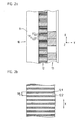
- the sampled incremental track 12 has two different pitch periods TP G , TP F and in this embodiment consists of a periodic sequence of first and second blocks B1, B2.
- the sum of the widths of two successive blocks B1, B2 defines the pitch period TP G , which represents the coarser of the two pitch periods TP G , TP F in the incremental track 12.
- the widths of the two blocks B1, B2 are selected to be identical; However, for the sampling, above all, the coarse graduation period TP G defined by the sum of the widths is important.
- the first blocks B1 are designed to be slightly reflective; the second blocks B2, however, consist of a periodic sequence of further subregions 12.1, 12.2 with low and highly reflective optical properties.
- An enlarged detail of a second block B2 is shown in FIG. 2b shown. How out FIG. 2b can be seen, the sub-areas 12.1, 12.2 are formed in the second blocks B2 as narrow rectangular areas whose longitudinal axes extend in the y-direction in the scale plane, ie are oriented perpendicular to the measuring direction x.
- the different subregions 12.1, 12.2 in the second blocks B2 each have the same dimensions. About the sum of the widths of two successive sections 12.1, 12.2 in the first blocks B1 defines the fine pitch period TP F of the incremental track 12, as also shown in FIG FIG. 2b is illustrated.
- the coarser graduation period TP G of the incremental track 12 should be selected as an integer multiple of the finer graduation period TP F. Only in this way is it ensured that successive blocks B2 represent parts of a continuous incremental graduation with the finer graduation period TP F. It must therefore be ensured that over the entire measuring length away always low-reflecting sub-areas 12.1 and highly reflective sub-areas 12.2 are arranged alternately; in particular even when the incremental graduation with the finer graduation period TP F is interrupted by the low-reflection blocks B1. For example, a highly reflective partial area 12.1 at the edge of a block B2 in the block B2 immediately adjacent in the measuring direction is followed by a highly reflective partial area 12.2, etc. The representation of the incremental track 12 in FIG FIG. 2a Otherwise, this does not show in detail.
- the bit width of the pseudo-random code of the absolute track 13 is also tuned in this exemplary embodiment. This means that the width of the subregions 13.1, 13.2 in the absolute track 13 in the measuring direction x is selected to be identical to the graduation period TP G of the incremental track 12.
- scanning unit 20 comprises a light source 21, for example an LED, a collimator optics 22, a scanning plate 23 and a detector unit 24 for detecting the various scanning signals.
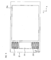
- a view of the scanning plate 23 is shown in plan view in FIG FIG. 3 shown.
- the light bundles contributing to the generation of the incremental signals INC F , INC G1 , INC G2 pass through different regions, depending on which of the various incremental signals INC F , INC G1 , INC G2 they contribute.
- the different areas on the scanning plate 23 are also assigned to defined areas defined in the detection plane, in each of which a Vernier strip system is generated.
- the light bundles ultimately used for generating the fine incremental signals INC F and the first coarse incremental signals INC G1 pass through the transparent window area of the scanning plate 23, designated by the reference numeral 23.1.
- the light bundles used to generate the second coarse incremental signals INC G2 pass through two areas in each of which a scanning 23.2, 23.3 is arranged.
- the scanning structures 23.2, 23.3 are in each case designed as permeable and impermeable partial regions formed periodically in the measuring direction x.
- the transmissive subregions of the scanning structures 23.2, 23.3 are shown of the FIG. 3 roughly diamond-shaped; Ideally, however, the transmissive sections have sinusoidal outer contours. Concerning. Further dimensioning measures on the part of the scanning structures 23.2, 23.3, reference is made to the following description.
- the respective beams for generating the incremental signals INC F , INC G1 , INC G2 hit the incremental track 12 on the scale 10 and are reflected back therefrom in the direction of the scanning plate 23.
- the back-reflected bundles of rays pass through a transparent window area 23.4 before they strike the respective incremental signal detector arrangements 24.1, 24.2, 24.3 in the detector unit 24.
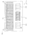
- FIG. 1 is only one of the incremental signal detector assemblies 24.1, 24.2, 24.3 recognizable, which is why in relation to the concrete structure of the detector unit 24 to the schematically illustrated plan view of the detector plane in FIG. 4 referenced. How out FIG.
- a first incremental signal detector arrangement 24.1 for generating the fine incremental signals INC F with the signal period SP F and for simultaneously generating the first coarse incremental signals INC G1 with the signal period SP G is provided on the detector unit 24 side.
- the scanning unit 20 according to the invention comprises at least one second incremental signal detector arrangement 24.2, 24.3 for generating the second coarse incremental signals INC G2 , which likewise have the signal period SP G.
- a pair of incremental signals are generated, each of which is 90 ° out of phase with each other.
- FIG. 4 A view of the detector plane of the detector unit 24 is shown in schematic form in FIG FIG. 4 shown.
- the absolute position signal detector assembly 24.4 can be seen, which consists of a plurality of individual optoelectronic detector elements which are arranged successively in the measuring direction x.
- Each two adjacent detector elements are used in the illustrated embodiment to sample a bit of the pseudo-random code in the absolute track 13, ie there are two groups of detector elements which are used to sample the bits of the pseudo-random code.
- only one of the two detector elements per bit is read out, which in FIG. 4 is to be illustrated via the schematically indicated switching elements SA - SN on the detector elements.
- two detector elements which are assigned to a bit width are in turn associated with such a switching element SA-SN.
- the selective readout of the respective detector element takes place as a function of which of the two groups of detector elements lies closer in the middle of the respective bit fields of the pseudo random code.
- the incremental signal INC G1 with the coarser signal period SP G is used in measuring operation.
- the scanning signals generated in the detector elements of the absolute position signal detector arrangement 24.4 are each supplied with trigger elements (not shown) which deliver signals with logical HIGH and LOW levels on the output side, which are processed further for absolute position determination.
- the trigger elements in integrated form are also arranged on the carrier substrate of the detector unit 24.
- a reference signal which either has a constant signal level or is varied in a known manner as a function of the signal level of the scanning signals.
- the output signals of the trigger elements are fed to a signal processing unit, also not shown, which further processes these as well as the generated incremental signals and generates an output signal ABS which indicates the desired coarse absolute position.
- the average first incremental signal detector arrangement 24.1 is used to generate the fine incremental signals INC F and the first coarse incremental signals INC G1 .
- the previously mentioned German Patent Application No. 199 62 278.7 In particular, referred to the second embodiment described therein.
- the second incremental signal detector arrangement 24.2a, 24.2b which is used to generate the second coarse incremental signal INC G2 , in the present exemplary embodiment consists of a total of two separate detector units 24.2a, 24.2b, which are identical, so-called structured detector arrangements or detector elements Arrays are formed. In principle, in the context of the present invention, the second incremental signal detector arrangement could also comprise only a single such detector unit.
- the illustrated detector units 24.2a, 24.2b consist in a known manner of a plurality of individual, rectangular optoelectronic detector elements which are all identical within a detector unit 24.2a, 24.2b and arranged adjacent to each other in the measuring direction x.
- each detector element of a detector unit 24.2a, 24.2b is each interconnected on the output side, which provide in-phase scanning signals.
- each detector element is interconnected in the two detector units 24.2a, 24.2b so that on the output side there are four partial incremental signals phase-shifted by 90 ° per detector unit 24.2a, 24.2b; these are interconnected with one another in a known manner to produce two coarse increment signals INC G2 phase-shifted by 90 °, which results in FIG. 4 not shown.
- INC G2 coarse increment signals
- the detection plane 24.2a, 24.2b respectively periodic stripe patterns are present in the region of the second incremental signal detector arrangement resulting from the interaction of the radiation beam emitted by the light source 21 with the incremental track 12 and with the respective associated scanning structures 23.2, 23.3 in the scanning plate 23 and used to generate the second coarse incremental signals INC G2 with the signal period SP G.
- the transparent regions of the scanning structures 23.2, 23.3 in the scanning plate 23 have a maximum width b AS in the measuring direction which is smaller than the width b DET of the associated detector elements in the structured detector arrangements of the second incremental signal detector arrangement 24.2a, 24.2b.
- the generation of the second coarse incremental signal INC G2 consequently corresponds to the generation of an incremental signal in the first exemplary embodiment of the mentioned German Patent Application No. 199 62 278.7 , With regard to details of this type of signal generation, reference is therefore expressly made to the disclosure of this document.
- the described embodiment of the position measuring device provides from the scanning of the incremental track 12 now a fine incremental signal INC F with the signal period SP F and the two coarse incremental signals INC G1 , INC G2 with the identical signal period SP G.
- the various scanning signals can already be appropriately billed or combined with one another on the part of the device according to the invention in order to precisely determine the respectively current absolute position; but it is also possible to transmit the different scanning signals to a downstream evaluation unit, where the determination of the absolute position of these signals takes place, etc. ..
- the measures according to the invention provide in the calculation or synchronization of the different scanning signals INC F , INC G1 , INC G2 and ABS now sure that even in the event of a possible pitch movement of the scanning result relative to the scale no errors.
- tilting of the scale and scanning unit about an axis which lies in the scale plane or parallel to the scale plane and is oriented perpendicular to the measurement direction may be defined by a pitch movement or pitch tilt.
- FIGS. 5a-5d and 6 directed.
- the case of a correct alignment of scale 10 and scanning unit 20 in conjunction with the resulting two coarse incremental signals INC G1 , INC G2 and the absolute position signal ABS shown; on the right is the case of a possible pitch tilt illustrated.
- the position measuring device ensures that in the case of such a pitch movement on the one hand, the same behavior of the fine incremental signal INC F and the first coarse incremental signal INC G1 results; On the other hand, in this case it is ensured according to the invention that the second coarse incremental signal INC G2 and the absolute position signal ABS show a largely similar behavior in the event of a pitching movement.
- a phase offset ⁇ G1-G2 which is dependent on the pitch angle ⁇ , results between the two signals INC G1 , INC G2 , into which the relatively small difference of the height of the respective detector arrangements exceeds the scale.
- the two scanning signals generated from a track in the form of the two coarse incremental signals INC G1 , INC G2 consequently have a different pitch behavior.
- the two coarse incremental signals INC G1 , INC G2 are in phase with the same signal period; this case is on the left side of the two FIGS. 5a and 5b illustrated.
- phase offset ⁇ G1-G2 or a phase difference between the two coarse incremental signals INC G1 , INC G2 results, as can be seen from the right-hand part of FIGS. 5b and 5c is apparent.
- the phase offset ⁇ G1-G2 between the two coarse incremental signals INC G1 , INC G2 is due to the different generation or the different scanning beam path of the two coarse incremental signals INC G1 , INC G2 .
- G1 moves at a present pitch tilt the stripe pattern generated in the detection plane is tilt angle-dependent and thus indicates a supposed position change, resulting in an error in the position determination.
- the strip pattern resulting in the detection plane remains almost stationary even on such a pitch tilt on the respective detector unit, ie, the correct position value also results in the case of such pitch tilting.
- FIG. 6 shows a schematic partial view of the position measuring device according to the invention.
- other scanning arrangements result of course other relationships between the phase difference and the respective pitch angle.
- the behavior of the absolute position signal ABS in the case of a possible pitch tilt is otherwise in FIG. 5d illustrated.
- the absolute position signal ABS also experiences a shift during the pitch movement due to the corresponding scanning beam path, but in this case it behaves only slightly differently than the second coarse increment signal INC G2 .
- the relative position of the absolute position signal ABS to the second coarse incremental signal INC G remains unchanged even in the case of a pitch movement within certain limits.
- a corresponding monitoring and determination of the phase difference ⁇ G1-G2 can be carried out in a comparator unit which is assigned to the position measuring device and via which the two tracking signals generated with different pitch behavior are compared with one another for detecting a possible pitch tilt.
- a comparator unit can in this case be arranged both on the side of the position-measuring device, such as on the side of an evaluation unit, which is arranged downstream of the position-measuring device.
- a correction of the spatial orientation of the scale and the scanning unit takes place when a maximum allowable pitch tilt is exceeded. If a maximum allowable pitch tilt is exceeded, an optical or audible warning signal is generated.
- the monitoring can take place here, for example during assembly in the form of an immediate visual display of the currently determined phase difference ⁇ G1-G2 on a suitable display unit. Alternatively, however, it may also be provided to carry out this comparison continuously in an automated manner and to generate a warning signal only in the event of a fault, ie, if approximately ⁇ G1-G2 > ⁇ G1-G2, max . Likewise, however, also in the actual measuring operation This phase difference can be monitored and in the event of a fault, a suitable warning signal can be generated, etc.
Landscapes
- Physics & Mathematics (AREA)
- General Physics & Mathematics (AREA)
- Optical Transform (AREA)
- Vehicle Body Suspensions (AREA)
- Body Structure For Vehicles (AREA)
- Analysing Materials By The Use Of Radiation (AREA)
Applications Claiming Priority (2)
| Application Number | Priority Date | Filing Date | Title |
|---|---|---|---|
| DE10130938 | 2001-06-27 | ||
| DE10130938A DE10130938A1 (de) | 2001-06-27 | 2001-06-27 | Positionsmesseinrichtung und Verfahren zum Betrieb einer Positionsmesseinrichtung |
Publications (2)
| Publication Number | Publication Date |
|---|---|
| EP1271107A1 EP1271107A1 (de) | 2003-01-02 |
| EP1271107B1 true EP1271107B1 (de) | 2009-08-19 |
Family
ID=7689603
Family Applications (1)
| Application Number | Title | Priority Date | Filing Date |
|---|---|---|---|
| EP02012780A Expired - Lifetime EP1271107B1 (de) | 2001-06-27 | 2002-06-10 | Positionsmesseinrichtung |
Country Status (6)
| Country | Link |
|---|---|
| US (1) | US6914235B2 (https=) |
| EP (1) | EP1271107B1 (https=) |
| JP (1) | JP4233814B2 (https=) |
| AT (1) | ATE440266T1 (https=) |
| DE (2) | DE10130938A1 (https=) |
| ES (1) | ES2329878T3 (https=) |
Families Citing this family (18)
| Publication number | Priority date | Publication date | Assignee | Title |
|---|---|---|---|---|
| GB0413827D0 (en) | 2004-06-21 | 2004-07-21 | Renishaw Plc | Scale reading apparatus |
| GB0428165D0 (en) * | 2004-12-23 | 2005-01-26 | Renishaw Plc | Position measurement |
| DE102005015743B4 (de) * | 2005-04-06 | 2018-08-23 | Dr. Johannes Heidenhain Gmbh | Abtasteinheit für eine Positionsmesseinrichtung zum optischen Abtasten einer Maßverkörperung und Positionsmesseinrichtung |
| JP4951885B2 (ja) * | 2005-06-29 | 2012-06-13 | ミツミ電機株式会社 | エンコーダ装置 |
| DE102006029650B4 (de) * | 2006-06-28 | 2020-02-20 | Dr. Johannes Heidenhain Gmbh | Schaltungsanordung und Verfahren zur Kippfehlerermittlung an einer Positionsmesseinrichtung |
| US7943897B2 (en) * | 2007-06-20 | 2011-05-17 | Sharp Kabushiki Kaisha | Optical encoder and electronic equipment |
| DE102007033009A1 (de) | 2007-07-12 | 2009-01-15 | Dr. Johannes Heidenhain Gmbh | Verfahren und Vorrichtung zur Übertragung von Signalen von einer Positionsmesseinrichtung zu einer Auswerteeinheit |
| DE102007056612A1 (de) * | 2007-11-23 | 2009-05-28 | Dr. Johannes Heidenhain Gmbh | Optische Positionsmesseinrichtung |
| GB0819767D0 (en) * | 2008-10-28 | 2008-12-03 | Renishaw Plc | Absolute encoder setup indication |
| JP4816988B1 (ja) * | 2011-02-10 | 2011-11-16 | 株式会社安川電機 | エンコーダ、光学モジュール及びサーボシステム |
| DE102011007459B4 (de) | 2011-04-15 | 2023-05-11 | Dr. Johannes Heidenhain Gmbh | Optische Längenmesseinrichtung |
| DE102012212767A1 (de) * | 2012-07-20 | 2014-01-23 | Dr. Johannes Heidenhain Gmbh | Positionsmesseinrichtung |
| EP3015828B1 (en) | 2014-10-30 | 2016-09-28 | Fagor, S. Coop. | Optoelectronic device and method thereof |
| CN106052724B (zh) * | 2016-05-19 | 2019-01-25 | 深圳市越疆科技有限公司 | 一种机器人、旋转测量装置及方法 |
| JP6953772B2 (ja) * | 2017-04-13 | 2021-10-27 | 株式会社ニコン | 誤差検出方法、誤差検出プログラム、誤差検出装置、エンコーダ装置の製造方法、エンコーダ装置、駆動装置、ステージ装置、及びロボット装置 |
| US10859363B2 (en) | 2017-09-27 | 2020-12-08 | Stanley Black & Decker, Inc. | Tape rule assembly with linear optical encoder for sensing human-readable graduations of length |
| JP7293660B2 (ja) * | 2019-01-18 | 2023-06-20 | 株式会社ジェイテクト | 回転角検出装置 |
| JP7210103B2 (ja) * | 2019-01-28 | 2023-01-23 | 株式会社ミツトヨ | エンコーダの寿命検出装置 |
Family Cites Families (12)
| Publication number | Priority date | Publication date | Assignee | Title |
|---|---|---|---|---|
| GB1174145A (en) * | 1967-08-04 | 1969-12-10 | British Aircraft Corp Ltd | Measuring Systems |
| GB2116313B (en) | 1982-02-25 | 1985-09-04 | Ferranti Plc | Sine wave generator for position encoder |
| DE3726678C1 (de) | 1987-08-11 | 1989-03-09 | Heidenhain Gmbh Dr Johannes | Inkrementale Laengen- oder Winkelmesseinrichtung |
| EP0555507B1 (de) * | 1992-02-14 | 1995-01-11 | Dr. Johannes Heidenhain GmbH | Wegmesseinrichtung |
| CH690971A5 (de) | 1994-02-25 | 2001-03-15 | Hera Rotterdam Bv | Verfahren zur Messung und Verwertung einer Verschiebung eines Abtastkopfes gegenüber einer Massverkörperung und optischer Messgeber zur Durchführung dieses Verfahrens. |
| US6229140B1 (en) * | 1995-10-27 | 2001-05-08 | Canon Kabushiki Kaisha | Displacement information detection apparatus |
| JPH1033636A (ja) | 1996-05-03 | 1998-02-10 | Yuyama Seisakusho:Kk | 薬剤分包装置、薬瓶及び薬剤検査方法 |
| DE19642200A1 (de) | 1996-10-12 | 1998-04-16 | Heidenhain Gmbh Dr Johannes | Kontrollvorrichtung und Verfahren zur Prüfung von positionsabhängigen Abtastsignalen |
| DE19859670A1 (de) | 1998-12-23 | 2000-06-29 | Heidenhain Gmbh Dr Johannes | Abtastkopf und Verfahren zu dessen Herstellung |
| DE19908328A1 (de) | 1999-02-26 | 2000-08-31 | Heidenhain Gmbh Dr Johannes | Optische Positionsmeßeinrichtung |
| DE19941318A1 (de) * | 1999-08-31 | 2001-03-15 | Heidenhain Gmbh Dr Johannes | Optische Positionsmeßeinrichtung |
| DE19962278A1 (de) * | 1999-12-23 | 2001-08-02 | Heidenhain Gmbh Dr Johannes | Positionsmeßeinrichtung |
-
2001
- 2001-06-27 DE DE10130938A patent/DE10130938A1/de not_active Withdrawn
-
2002
- 2002-06-10 DE DE50213775T patent/DE50213775D1/de not_active Expired - Lifetime
- 2002-06-10 EP EP02012780A patent/EP1271107B1/de not_active Expired - Lifetime
- 2002-06-10 AT AT02012780T patent/ATE440266T1/de not_active IP Right Cessation
- 2002-06-10 ES ES02012780T patent/ES2329878T3/es not_active Expired - Lifetime
- 2002-06-18 JP JP2002177199A patent/JP4233814B2/ja not_active Expired - Fee Related
- 2002-06-26 US US10/180,916 patent/US6914235B2/en not_active Expired - Lifetime
Also Published As
| Publication number | Publication date |
|---|---|
| ES2329878T3 (es) | 2009-12-02 |
| DE50213775D1 (de) | 2009-10-01 |
| ATE440266T1 (de) | 2009-09-15 |
| JP2003042810A (ja) | 2003-02-13 |
| EP1271107A1 (de) | 2003-01-02 |
| US6914235B2 (en) | 2005-07-05 |
| US20030016369A1 (en) | 2003-01-23 |
| JP4233814B2 (ja) | 2009-03-04 |
| DE10130938A1 (de) | 2003-01-23 |
Similar Documents
| Publication | Publication Date | Title |
|---|---|---|
| EP1271107B1 (de) | Positionsmesseinrichtung | |
| EP1111345B1 (de) | Positionsmesseinrichtung mit Inkrementalspur mit zwei unterschiedlichen Teilungsperioden | |
| EP1081457B1 (de) | Optische Positionsmesseinrichtung | |
| EP1923672B1 (de) | Positionsmesseinrichtung | |
| EP1329696B1 (de) | Positionsmesseinrichtung mit Masstab | |
| EP1407231B1 (de) | Positionsmesseinrichtung | |
| EP0509979B1 (de) | Photoelektronische Positionsmesseinrichtung | |
| EP3511680B1 (de) | Positionsmesseinrichtung | |
| EP1691172B1 (de) | Positionsmesseinrichtung | |
| EP0513427A1 (de) | Interferentielle Positionsmessvorrichtung | |
| EP2063230B1 (de) | Optische Positionsmesseinrichtung | |
| EP0669518B1 (de) | Vorrichtung zum Erzeugen von positionsabhängigen Signalen | |
| EP1524503B1 (de) | Optische Positionsmesseinrichtung | |
| DE19726935B4 (de) | Optische Positionsmeßeinrichtung | |
| DE102007024593A1 (de) | Maßstab für eine Positionsmesseinrichtung und Positionsmesseinrichtung | |
| EP3527951B1 (de) | Optische positionsmesseinrichtung | |
| EP1028309B1 (de) | Optische Positionsmesseinrichtung | |
| EP1085291B1 (de) | Vorrichtung zur Positionsbestimmung und Ermittlung von Führungsfehlern | |
| DE10020575A1 (de) | Abtasteinheit für eine optische Positionsmesseinrichtung | |
| EP0754933A2 (de) | Positionsmessvorrichtung | |
| EP1427985A1 (de) | Positionsmesseinrichtung und verfahren zum betrieb einer positionsmesseinrichtung | |
| EP2878930B1 (de) | Positionsmesseinrichtung | |
| EP1724548A2 (de) | Positionsmessgerät | |
| DE102015225272B4 (de) | Optische Positionsmesseinrichtung | |
| DE102020134604B4 (de) | Vorrichtung und Verfahren zur Positionsbestimmung |
Legal Events
| Date | Code | Title | Description |
|---|---|---|---|
| PUAI | Public reference made under article 153(3) epc to a published international application that has entered the european phase |
Free format text: ORIGINAL CODE: 0009012 |
|
| AK | Designated contracting states |
Kind code of ref document: A1 Designated state(s): AT BE CH CY DE DK ES FI FR GB GR IE IT LI LU MC NL PT SE TR |
|
| AX | Request for extension of the european patent |
Free format text: AL;LT;LV;MK;RO;SI |
|
| 17P | Request for examination filed |
Effective date: 20030702 |
|
| AKX | Designation fees paid |
Designated state(s): AT BE CH CY DE DK ES FI FR GB GR IE IT LI LU MC NL PT SE TR |
|
| 17Q | First examination report despatched |
Effective date: 20080131 |
|
| GRAP | Despatch of communication of intention to grant a patent |
Free format text: ORIGINAL CODE: EPIDOSNIGR1 |
|
| GRAS | Grant fee paid |
Free format text: ORIGINAL CODE: EPIDOSNIGR3 |
|
| GRAA | (expected) grant |
Free format text: ORIGINAL CODE: 0009210 |
|
| AK | Designated contracting states |
Kind code of ref document: B1 Designated state(s): AT BE CH CY DE DK ES FI FR GB GR IE IT LI LU MC NL PT SE TR |
|
| REG | Reference to a national code |
Ref country code: GB Ref legal event code: FG4D Free format text: NOT ENGLISH |
|
| REG | Reference to a national code |
Ref country code: CH Ref legal event code: EP |
|
| REG | Reference to a national code |
Ref country code: IE Ref legal event code: FG4D |
|
| REF | Corresponds to: |
Ref document number: 50213775 Country of ref document: DE Date of ref document: 20091001 Kind code of ref document: P |
|
| REG | Reference to a national code |
Ref country code: ES Ref legal event code: FG2A Ref document number: 2329878 Country of ref document: ES Kind code of ref document: T3 |
|
| PG25 | Lapsed in a contracting state [announced via postgrant information from national office to epo] |
Ref country code: FI Free format text: LAPSE BECAUSE OF FAILURE TO SUBMIT A TRANSLATION OF THE DESCRIPTION OR TO PAY THE FEE WITHIN THE PRESCRIBED TIME-LIMIT Effective date: 20090819 Ref country code: SE Free format text: LAPSE BECAUSE OF FAILURE TO SUBMIT A TRANSLATION OF THE DESCRIPTION OR TO PAY THE FEE WITHIN THE PRESCRIBED TIME-LIMIT Effective date: 20090819 |
|
| NLV1 | Nl: lapsed or annulled due to failure to fulfill the requirements of art. 29p and 29m of the patents act | ||
| PG25 | Lapsed in a contracting state [announced via postgrant information from national office to epo] |
Ref country code: NL Free format text: LAPSE BECAUSE OF FAILURE TO SUBMIT A TRANSLATION OF THE DESCRIPTION OR TO PAY THE FEE WITHIN THE PRESCRIBED TIME-LIMIT Effective date: 20090819 |
|
| REG | Reference to a national code |
Ref country code: IE Ref legal event code: FD4D |
|
| PG25 | Lapsed in a contracting state [announced via postgrant information from national office to epo] |
Ref country code: CY Free format text: LAPSE BECAUSE OF FAILURE TO SUBMIT A TRANSLATION OF THE DESCRIPTION OR TO PAY THE FEE WITHIN THE PRESCRIBED TIME-LIMIT Effective date: 20090819 Ref country code: PT Free format text: LAPSE BECAUSE OF FAILURE TO SUBMIT A TRANSLATION OF THE DESCRIPTION OR TO PAY THE FEE WITHIN THE PRESCRIBED TIME-LIMIT Effective date: 20091221 |
|
| PG25 | Lapsed in a contracting state [announced via postgrant information from national office to epo] |
Ref country code: DK Free format text: LAPSE BECAUSE OF FAILURE TO SUBMIT A TRANSLATION OF THE DESCRIPTION OR TO PAY THE FEE WITHIN THE PRESCRIBED TIME-LIMIT Effective date: 20090819 Ref country code: IE Free format text: LAPSE BECAUSE OF FAILURE TO SUBMIT A TRANSLATION OF THE DESCRIPTION OR TO PAY THE FEE WITHIN THE PRESCRIBED TIME-LIMIT Effective date: 20090819 |
|
| PLBE | No opposition filed within time limit |
Free format text: ORIGINAL CODE: 0009261 |
|
| STAA | Information on the status of an ep patent application or granted ep patent |
Free format text: STATUS: NO OPPOSITION FILED WITHIN TIME LIMIT |
|
| 26N | No opposition filed |
Effective date: 20100520 |
|
| PG25 | Lapsed in a contracting state [announced via postgrant information from national office to epo] |
Ref country code: GR Free format text: LAPSE BECAUSE OF FAILURE TO SUBMIT A TRANSLATION OF THE DESCRIPTION OR TO PAY THE FEE WITHIN THE PRESCRIBED TIME-LIMIT Effective date: 20091120 |
|
| BERE | Be: lapsed |
Owner name: DR. JOHANNES HEIDENHAIN G.M.B.H. Effective date: 20100630 |
|
| PG25 | Lapsed in a contracting state [announced via postgrant information from national office to epo] |
Ref country code: MC Free format text: LAPSE BECAUSE OF NON-PAYMENT OF DUE FEES Effective date: 20100630 |
|
| REG | Reference to a national code |
Ref country code: CH Ref legal event code: PL |
|
| REG | Reference to a national code |
Ref country code: FR Ref legal event code: ST Effective date: 20110228 |
|
| PG25 | Lapsed in a contracting state [announced via postgrant information from national office to epo] |
Ref country code: CH Free format text: LAPSE BECAUSE OF NON-PAYMENT OF DUE FEES Effective date: 20100630 Ref country code: LI Free format text: LAPSE BECAUSE OF NON-PAYMENT OF DUE FEES Effective date: 20100630 |
|
| PG25 | Lapsed in a contracting state [announced via postgrant information from national office to epo] |
Ref country code: FR Free format text: LAPSE BECAUSE OF NON-PAYMENT OF DUE FEES Effective date: 20100630 |
|
| PG25 | Lapsed in a contracting state [announced via postgrant information from national office to epo] |
Ref country code: BE Free format text: LAPSE BECAUSE OF NON-PAYMENT OF DUE FEES Effective date: 20100630 |
|
| PG25 | Lapsed in a contracting state [announced via postgrant information from national office to epo] |
Ref country code: AT Free format text: LAPSE BECAUSE OF NON-PAYMENT OF DUE FEES Effective date: 20100610 |
|
| PG25 | Lapsed in a contracting state [announced via postgrant information from national office to epo] |
Ref country code: LU Free format text: LAPSE BECAUSE OF NON-PAYMENT OF DUE FEES Effective date: 20100610 |
|
| PG25 | Lapsed in a contracting state [announced via postgrant information from national office to epo] |
Ref country code: TR Free format text: LAPSE BECAUSE OF FAILURE TO SUBMIT A TRANSLATION OF THE DESCRIPTION OR TO PAY THE FEE WITHIN THE PRESCRIBED TIME-LIMIT Effective date: 20090819 |
|
| PGFP | Annual fee paid to national office [announced via postgrant information from national office to epo] |
Ref country code: IT Payment date: 20140624 Year of fee payment: 13 |
|
| PG25 | Lapsed in a contracting state [announced via postgrant information from national office to epo] |
Ref country code: IT Free format text: LAPSE BECAUSE OF NON-PAYMENT OF DUE FEES Effective date: 20150610 |
|
| PGFP | Annual fee paid to national office [announced via postgrant information from national office to epo] |
Ref country code: GB Payment date: 20160621 Year of fee payment: 15 Ref country code: ES Payment date: 20160614 Year of fee payment: 15 |
|
| GBPC | Gb: european patent ceased through non-payment of renewal fee |
Effective date: 20170610 |
|
| PG25 | Lapsed in a contracting state [announced via postgrant information from national office to epo] |
Ref country code: GB Free format text: LAPSE BECAUSE OF NON-PAYMENT OF DUE FEES Effective date: 20170610 |
|
| REG | Reference to a national code |
Ref country code: ES Ref legal event code: FD2A Effective date: 20181112 |
|
| PG25 | Lapsed in a contracting state [announced via postgrant information from national office to epo] |
Ref country code: ES Free format text: LAPSE BECAUSE OF NON-PAYMENT OF DUE FEES Effective date: 20170611 |
|
| PGFP | Annual fee paid to national office [announced via postgrant information from national office to epo] |
Ref country code: DE Payment date: 20190619 Year of fee payment: 18 |
|
| REG | Reference to a national code |
Ref country code: DE Ref legal event code: R119 Ref document number: 50213775 Country of ref document: DE |
|
| PG25 | Lapsed in a contracting state [announced via postgrant information from national office to epo] |
Ref country code: DE Free format text: LAPSE BECAUSE OF NON-PAYMENT OF DUE FEES Effective date: 20210101 |