EP1270929A1 - Pompe a combustible et dispositif d'alimentation en combustible utilisant cette pompe - Google Patents
Pompe a combustible et dispositif d'alimentation en combustible utilisant cette pompe Download PDFInfo
- Publication number
- EP1270929A1 EP1270929A1 EP01902791A EP01902791A EP1270929A1 EP 1270929 A1 EP1270929 A1 EP 1270929A1 EP 01902791 A EP01902791 A EP 01902791A EP 01902791 A EP01902791 A EP 01902791A EP 1270929 A1 EP1270929 A1 EP 1270929A1
- Authority
- EP
- European Patent Office
- Prior art keywords
- fuel
- plungers
- moving process
- drive cams
- cam
- Prior art date
- Legal status (The legal status is an assumption and is not a legal conclusion. Google has not performed a legal analysis and makes no representation as to the accuracy of the status listed.)
- Withdrawn
Links
Images


Classifications
-
- F—MECHANICAL ENGINEERING; LIGHTING; HEATING; WEAPONS; BLASTING
- F02—COMBUSTION ENGINES; HOT-GAS OR COMBUSTION-PRODUCT ENGINE PLANTS
- F02M—SUPPLYING COMBUSTION ENGINES IN GENERAL WITH COMBUSTIBLE MIXTURES OR CONSTITUENTS THEREOF
- F02M59/00—Pumps specially adapted for fuel-injection and not provided for in groups F02M39/00 -F02M57/00, e.g. rotary cylinder-block type of pumps
- F02M59/02—Pumps specially adapted for fuel-injection and not provided for in groups F02M39/00 -F02M57/00, e.g. rotary cylinder-block type of pumps of reciprocating-piston or reciprocating-cylinder type
- F02M59/10—Pumps specially adapted for fuel-injection and not provided for in groups F02M39/00 -F02M57/00, e.g. rotary cylinder-block type of pumps of reciprocating-piston or reciprocating-cylinder type characterised by the piston-drive
-
- F—MECHANICAL ENGINEERING; LIGHTING; HEATING; WEAPONS; BLASTING
- F02—COMBUSTION ENGINES; HOT-GAS OR COMBUSTION-PRODUCT ENGINE PLANTS
- F02M—SUPPLYING COMBUSTION ENGINES IN GENERAL WITH COMBUSTIBLE MIXTURES OR CONSTITUENTS THEREOF
- F02M59/00—Pumps specially adapted for fuel-injection and not provided for in groups F02M39/00 -F02M57/00, e.g. rotary cylinder-block type of pumps
- F02M59/02—Pumps specially adapted for fuel-injection and not provided for in groups F02M39/00 -F02M57/00, e.g. rotary cylinder-block type of pumps of reciprocating-piston or reciprocating-cylinder type
- F02M59/08—Pumps specially adapted for fuel-injection and not provided for in groups F02M39/00 -F02M57/00, e.g. rotary cylinder-block type of pumps of reciprocating-piston or reciprocating-cylinder type characterised by two or more pumping elements with conjoint outlet or several pumping elements feeding one engine cylinder
-
- F—MECHANICAL ENGINEERING; LIGHTING; HEATING; WEAPONS; BLASTING
- F02—COMBUSTION ENGINES; HOT-GAS OR COMBUSTION-PRODUCT ENGINE PLANTS
- F02M—SUPPLYING COMBUSTION ENGINES IN GENERAL WITH COMBUSTIBLE MIXTURES OR CONSTITUENTS THEREOF
- F02M59/00—Pumps specially adapted for fuel-injection and not provided for in groups F02M39/00 -F02M57/00, e.g. rotary cylinder-block type of pumps
- F02M59/02—Pumps specially adapted for fuel-injection and not provided for in groups F02M39/00 -F02M57/00, e.g. rotary cylinder-block type of pumps of reciprocating-piston or reciprocating-cylinder type
- F02M59/10—Pumps specially adapted for fuel-injection and not provided for in groups F02M39/00 -F02M57/00, e.g. rotary cylinder-block type of pumps of reciprocating-piston or reciprocating-cylinder type characterised by the piston-drive
- F02M59/102—Mechanical drive, e.g. tappets or cams
-
- F—MECHANICAL ENGINEERING; LIGHTING; HEATING; WEAPONS; BLASTING
- F02—COMBUSTION ENGINES; HOT-GAS OR COMBUSTION-PRODUCT ENGINE PLANTS
- F02M—SUPPLYING COMBUSTION ENGINES IN GENERAL WITH COMBUSTIBLE MIXTURES OR CONSTITUENTS THEREOF
- F02M63/00—Other fuel-injection apparatus having pertinent characteristics not provided for in groups F02M39/00 - F02M57/00 or F02M67/00; Details, component parts, or accessories of fuel-injection apparatus, not provided for in, or of interest apart from, the apparatus of groups F02M39/00 - F02M61/00 or F02M67/00; Combination of fuel pump with other devices, e.g. lubricating oil pump
- F02M63/02—Fuel-injection apparatus having several injectors fed by a common pumping element, or having several pumping elements feeding a common injector; Fuel-injection apparatus having provisions for cutting-out pumps, pumping elements, or injectors; Fuel-injection apparatus having provisions for variably interconnecting pumping elements and injectors alternatively
- F02M63/0225—Fuel-injection apparatus having a common rail feeding several injectors ; Means for varying pressure in common rails; Pumps feeding common rails
Definitions
- the present invention relates to a fuel pump comprising a plurality of plungers and a camshaft having a plurality of drive cams, each provided H in correspondence to one of the plungers, which engages the plungers in reciprocal movement by rotating the camshaft, and a fuel feeding device that employs this fuel pump.
- a fuel feeding device adopting the so-called common rail system, which comprises a fuel pump, a common rail where high-pressure fuel force fed from the fuel pump is stored and fuel injection valves each provided in correspondence to one of the cylinders of an internal combustion engine to enable a fuel feed of the high-pressure fuel stored in the common rail to the cylinders
- the fuel pump normally includes two plungers and these plungers are caused to move reciprocally by drive cams provided as separate units at the camshaft to supply pressurized fuel to the common rail.
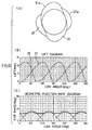
- a fuel pump such as the one described above normally assumes the shape shown in FIG. 7(A). Namely, cam lobes formed at the individual drive cams ⁇ and ⁇ are each formed to achieve a shape having portions used for a forward moving process and a backward moving process of the corresponding plunger, which are symmetrical with respect to each other and, thus, each drive cam takes on a triangular shape overall.
- the lift characteristics manifesting at each of the plungers driven by the drive cams ⁇ and ⁇ during the forward moving process in which the plunger travels from the bottom dead center to the top dead center and the lift characteristics manifesting at the same plunger during the backward moving process, in which the plunger travels from the top dead center to the bottom dead center achieve symmetry
- the lift characteristics of one of the plungers manifest as sine waves whose phase is offset by 60° from the sine waves representing the lift characteristics of the other plunder, as shown in FIG. 7(B).
- the geometric injection rate achieves characteristics whereby the value of the geometric injection rate continuously changes between 0 and the peak value every 60° of the cam rotating angle (cam angle), as shown in FIG. 7(C). Since the cam speed and the drive torque are roughly in proportion to the characteristics of the geometric injection rate, the plunger lift speed (i.e., the cam speed) and the drive torque, too, manifest characteristics whereby they fluctuate in a similar manner.
- the geometric injection rate (GIR) constantly fluctuate between 0 and the peak value over every 60°, causing a significant fluctuation in the pressure within the common rail.
- the pressure-withstanding performance of the product is normally designed by allowing an ample margin to comfortably tolerate even the upper limit of the pressure fluctuation to maximize the service life of the product
- the pressure-withstanding level of the overall system including the fuel injection valves, the common rail, the piping connecting the fuel pump with the common rail and the piping connecting the common rail with the fuel injection valves must the extremely high if the fluctuation of the pressure of the fuel let out from the fuel pump is great. For this reason, a significant fluctuation in the pressure gives rise to problems in that the weight of the product is bound to increase since the components need greater wall thicknesses and in that the structure of the product becomes more complicated in order to achieve better pressure-withstanding performance.
- the dimension of the camshaft along the radial direction increases if the diameter of the drive cams is increased, or the dimension of the camshaft along the axial direction increases F the wall thickness of the drive cams is increased. Furthermore, the dimension of the camshaft along the axial direction increases instead when the numbers of plungers and drive cams are increased.
- the drive torque constantly fluctuates between 0 and the peak value and, as a result, the load on the drive system and the noise occurring in the system are bound to be significant.
- the product must be designed by adopting a structure with ample margin for drive torque fluctuations, and thus, the drive system must be thick and heavy to tolerate such drive torque fluctuations.
- an object of the present invention is to provide a fuel pump having drive cams with which the problems discussed above can be solved and a fuel feeding device utilizing the fuel pump.
- the fuel pump according to the present invention comprising a plurality of plungers and a camshaft having a plurality of drive cams each provided in correspondence to one of the plurality of plungers with a motive force applied from the outside used to rotate the camshaft so as to engage the plurality of plungers in reciprocal movement with the corresponding drive cams and the fuel pressurized and force fed during a forward moving process of each of the plungers
- all or some of the plurality of drive cams are set by offsetting their phases from one another and each of the drive cams includes asymmetrical cam lobes each formed so as to reduce the extent of displacement of the corresponding plunger relative to a unit cam rotating angle during the forward moving process compared to the extent of displacement occurring during the backward moving process of the plunger.
- the fuel feeding device having a fuel pump, a common rail where high-pressure fuel force fed from the fuel pump is stored and fuel injection valves each provided in correspondence to one of the cylinders of an internal combustion engine which allow the high-pressure fuel stored in the common rail to be fed with the fuel pump comprising a plurality of plungers and a camshaft having a plurality of drive cams each provided in correspondence to one of the plurality of plungers, a motive force applied from the outside used to rotate the camshaft to engage the plurality of plungers in reciprocal movement with the corresponding drive cams and the fuel pressurized and force fed during a forward moving process of each of the plungers, all or some of the plurality of drive cams are set by offsetting their phases from one another and each of the drive cams includes asymmetrical cam lobes each formed so as to reduce the extent of displacement of the corresponding plunger relative to a unit cam rotating angle during the forward moving process compared to the extent of displacement occurring during the backward moving process
- the plunger can be lifted more slowly compared to the prior art during the forward moving process and also the plunger can be reset quickly during the backward moving process even if the number of cam lobes provided at each drive cam is the same as that in the related art.
- the geometric injection rate of the fuel pump and the maximum drive torque which is in proportion to the geometric injection rate, can be set smaller than those in a structure utilizing the symmetrical cams in the related art.
- the can lobes assume an asymmetrical shape whereby the extent of plunger displacement relative to the unit cam rotating angle is smaller during the forward moving process than in the backward moving process and, as a result, it is possible achieve a larger radius of curvature at the cam nose than in the prior art.
- cam lobes at the drive cams so that they assume a concave shape over the areas corresponding to the backward moving process of the plungers.
- the angle range of the drive cams required for the backward moving process can be further reduced so as to assure a larger angle range allocated for the backward moving process while ensuring that the plungers move along the backward direction quickly.
- the portion of each cam lobe corresponding to the backward moving process should be formed over an angle range in which jumping of the plunger or the tappet provided between the plunger and the cam lobe is prevented, the shape described above is particularly effective when a large number of cam lobes are formed with a small angle range allocated for each cam lobe and thus, it is necessary to lift the plungers slowly by maximizing the angle range corresponding to the forward moving process.
- asymmetrical cam lobes be formed at the plurality of drive cams so that the injection rates of the individual plungers achieve a roughly constant total over a given cam rotating angle.
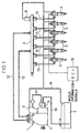
- the fuel feeding device comprises a fuel pump 1 that pressurizes and then feeds the pressurized fuel, a common rail 2 in which the fuel is accumulated and fuel injection valves 3 each provided in correspondence to one of the cylinders of an internal combustion engine.
- the fuel pump 1 which includes two plungers to be detailed later, is constituted by assembling a supply pump 4 that pressurizes the fuel induced thereto and then force feeds the pressurized fuel, a fuel metering unit (FMU) 5 that adjusts the quantity of fuel oil to be supplied to the supply pump 4 and a feed pump 6 that draws up the fuel and supplies the fuel to the FMU 5.
- a supply pump 4 that pressurizes the fuel induced thereto and then force feeds the pressurized fuel
- FMU fuel metering unit
- the fuel feeding device which includes a piping 10 connecting a fuel tank 7 with the feed pump 6, a piping 11 connecting the feed pump 6 with the FMU 5, a piping 12 connecting the supply pump 4 of the fuel pump 1 with the common rail 2 and pipings 13 connecting the common rail 2 with the individual fuel injection valves 3, the fuel oil drawn up from the fuel tank 7 by the feed pump 6 is supplied to the fuel metering unit (FMU) 5 where the quantity of the fuel to be supplied to the supply pump 4 is adjusted, the fuel alternately pressurized by the two plungers is force fed to the common rail 2 and the fuel is then fed to the individual fuel injection valves 3 from the common rail 2.
- FMU fuel metering unit
- the fuel feeding device further includes an overflow valve (not shown) provided at the fuel pump 1, a pressure limiting valve 8 that is provided at the common rail 2 and discharges the fuel oil inside the rail if the fuel oil pressure inside the rail reaches a level equal to or higher than a specific pressure level and a piping 14 that connects the individual fuel outlets communicating with the control chambers (not shown) at the fuel injection valves 3 to the fuel tank 7.
- an overflow valve (not shown) provided at the fuel pump 1
- a pressure limiting valve 8 that is provided at the common rail 2 and discharges the fuel oil inside the rail if the fuel oil pressure inside the rail reaches a level equal to or higher than a specific pressure level
- a piping 14 that connects the individual fuel outlets communicating with the control chambers (not shown) at the fuel injection valves 3 to the fuel tank 7.
- the fuel feeding device that is capable of returning the fuel with its pressure equal to or higher than a specific pressure level, which has been supplied to the supply pump 4 via the FMU 5 from the feed pump 6, to the fuel tank 7, also prevents the pressure inside the common rail from rising excessively by returning the fuel inside the common rail 2 to the fuel tank 7 if the pressure of the fuel inside the common rail 2 rises to a level equal to or higher than a specific pressure level and allows the high-pressure fuel in the control chambers (not shown) at the fuel injection valves 3 to flow out to the fuel tank 7 at an injection start to open the fuel injection valves 3.
- the fuel injection valves 3 which engages in operation in response to control signals generated through arithmetic processing executed at an electronic control unit (ECU) 15 based upon various information signals indicating, for instance, the engine rotation rate and the like detected at various sensors and switches (not shown), inject the high-pressure fuel inside the common rail with optimal injection timing at an optimal injection quantity.
- ECU electronice control unit
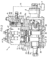
- FIGS. 2 through 4 show the fuel pump described above.
- the supply pump 4 constituting a part of the fuel pump 1 includes plungers 21, plunger barrels 22, tappets 23 and a camshaft 24, and the camshaft 24, which is supported by a pump housing 25, receives a drive torque from the engine (not shown) at one end thereof projecting out to the outside through the pump housing 25 so as to rotate in synchronization with the engine.
- the pump housing 25 is constituted of a housing member 25a having longitudinal holes 27 at which the plunger barrels 22 are mounted and housing members 25b and 25c that are secured to the housing member 25a with bolts or the like and rotatably hold the camshaft 24 near the two ends of the camshaft 24.
- two longitudinal holes 27 are formed at the housing member 25a, with the plunger barrels 22 secured to the housing member 25a inside the individual longitudinal holes and the plungers 21 inserted at the plunger barrels 22 so as to be allowed to make reciprocal movement freely.
- camshaft 24 is supported by the housing members 25b and 25c near its two ends via radial bearings 28 and 29 so as to allow play along the axial direction.
- two drive cams 31 and 32 are formed between the bearings, at phases offset from each other, each in correspondence to one of the plungers.
- the lower ends of the plungers 21 are placed in contact with the tappets 23 at which tappet rollers 23a in contact with the drive cams 31 and 32 are held, and springs 35 are provided between spring receptacles 33 at the housing member 25a and spring receptacles 34 located at the bottom of the plungers 21.
- springs 35 are provided between spring receptacles 33 at the housing member 25a and spring receptacles 34 located at the bottom of the plungers 21.
- an IO valve (inlet/outlet valve) 37 mounted between the plunger barrel and a delivery valve holder 36 is provided. Between the IO valve 37 and the plunger 21, a plunger chamber 38 is formed, with a fuel outlet 39 formed at the delivery valve holder 36 provided above the IO valve 37.
- the IO valve 37 which has a function of feeding the fuel oil supplied from the fuel metering unit (FMU) 5 to be detailed later, to the plunger chamber 38 and letting out the fuel compressed by the plunger 21 through the fuel outlet 39 so as to prevent the fuel from flowing back to the FMU 5, comprises a valve body 40 mounted at the top of plunger barrel 22, an inlet valve that opens/closes a fuel passage 41 having one end thereof communicating with the FMU 5 and another end thereof communicating with the plunger chamber 38 and formed at the valve body 40 and applies a constant force to the fuel passage 1 along the closing direction by using the force against the pressure of the fuel from the FMU 5 and an outlet valve 44 that opens/closes a fuel passage 43 having one end thereof communicating with the plunger chamber 38 and another end thereof communicating with the fuel outlet 39 and applies a constant force to the fuel passage 43 along the closing direction by utilizing the force against the pressure of the fuel from the plunger chamber 38.
- FMU fuel metering unit
- the outlet valve 44 closes to allow the fuel from the FMU 5 to push up the inlet valve 42 and thus, the fuel flows into the plunger chamber 38, whereas when the plunger 21 enters the ascending process, the pressurized fuel closes the inlet valve 42 thereby pushing up the outlet valve 44 and, as a result, the fuel is force fed through the fuel outlet 39.
- the fuel metering unit (FMU) 5 of the fuel pump has a function of delivering the fuel supplied from the feed pump 6 to the IO valves 37 after adjusting the fuel quantity so as to achieve the fuel pressure required in the engine. It includes throttle valves 47 each provided in the middle of a fuel passage 46 through which the fuel supplied from the feed pump 6 is guided to the IO valve 37 provided in conjunction with each plunger.
- the feed pump 6 of the fuel pump which draws up the fuel from the fuel tank 7 and feeds the fuel to the fuel metering unit (FMU) 5, is mounted with bolts or the like so as to close off the opening formed at the housing member 25c of the pump housing 25.
- the feed pump 6 draws up the fuel from the fuel tank 7 by utilizing a gear pump constituted of a main gear and a slave gear (not shown) as the camshaft 24 rotates, and then feeds the fuel to the fuel metering unit (FMU) 5 via a fuel filter (not shown).
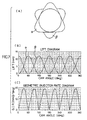
- the two drive cams 31 and 32 employed in this fuel pump have shapes identical to each other and, as shown in FIG. 5(A), they include can lobes 31a and 32a respectively, formed over 120° intervals.
- One of the drive cams is set at a phase offset from the phase of the other drive . cam by 60° so as to allow the forward moving process of a plunger effected by one of the drive cams to overlap the backward moving process of the other plunger effected by the second drive cam.
- cam lobes 31a and 32a are each formed in an asymmetrical shape so as to reduce the extent of the displacement of the lift of the plunger 21 per unit of cam rotating angle during the forward moving process of the plunger 21 than during the backward moving process of the plunger 21.
- the length of time (the cam rotating angle) corresponding to the forward moving process (the ascending process) of the plunger during which the volumetric capacity of the plunger chamber is reduced is set the length of time (the cam rotating angle) corresponding to the backward moving process (the descending process) during which the volumetric capacity of the plunger chamber is increased, in order to maximize the angle range of the cam lobes 31a and 32a utilized for the forward moving process.
- the cam lobes 31a and 32a each take on a gentle convex shape over the forward moving process and assume a concave shape over the backward moving process.
- the portion of the cam lobe formed in the convex shape to effect the backward moving process should be formed over the smallest possible angle range over which jumping of the plunger or the tappet is prevented.
- approximately 80° is allocated to be utilized for the forward moving process and the remaining 40° is allocated to be used for the backward moving process.
- the fluctuation of the injection rate in the fuel pump 1 is lessened compared to the prior art to reduce the extent of the pressure fluctuation occurring at the common rail 2.
- the fluctuation of the drive torque, too can be reduced compared to the prior art, and as the drive torque is reduced in this manner, the load on the drive system and the noise, too, can be reduced.
- cam lobes 31a and 32a at the drive cams 31 and 32 respectively shown in FIG. 5(A) are adjusted so as to achieve an almost constant total of the injection rates achieved by the individual plungers 21 relative to the cam rotating angle.
- the plunger 21 driven by one of the drive cams reaches the peak position (12mm in this example) and thus the fuel feed is completed, the plunger driven by the other drive cam starts to lift, and this starts a fuel feed.
- the composite injection rate (the composite speed) of the two plungers corresponding to a full rotation of the camshaft 24 and a 360° rotation of each drive cam i.e., the total of the injection rates relative to the cam rotating angle, can be sustained at an almost constant level as indicated by the bold line in FIG. 5(C).
- the lift start point for one of the plungers is set ahead of the time point at which the other plunger reaches the highest lift position by an approximately 20° cam rotating angle.
- the injection pump 1 having such drive cams 31 and 32 allows the plungers 21 to ascend slowly during the forward moving process and thus, the radius of curvature of the cam nose can be increased compared to that of the symmetrical cams shown in FIG. 7(A) to achieve an added advantage of reduced pressure applied to the surfaces of the drive cams.
- the contact pressure at the areas where the tappet rollers 23a and the drive cams 31 and 32 come into contact with each other can be kept down (the level of the force imparted from the tappet rollers 23a onto the cam surfaces can be kept down) and since this eliminates the necessity to allow a large diameter at the tappet rollers 23a to withstand a high surface pressure at the cam surfaces, the diameter of the tappet rollers 23a can be reduced.
- the angle range allocated for the backward moving process can be reduced, which allows the plungers to be lifted slowly by minimizing the cam speed during the forward moving process and also allows the plungers to make a quick backward movement during the backward moving process.
- a larger angle range can be allocated for the forward moving process by forming the portions of the cam lobes corresponding to the backward moving process in a concave shape to eliminate the necessity to lift the plungers fast, i.e., the cam speed and ultimately, the drive torque, too, can be reduced.
- the pressure-withstanding level for the entire system including the fuel injection valves, the common rail 2 and the piping 12 can be lowered since the extent of the pressure fluctuation itself is minimized. Since this, in turn, allows the components to have smaller wall thicknesses, a reduction in the weight of the product is achieved and the product does not need to assume a complicated structure to assure high pressure-withstanding performance either. If, on the other hand, the system is designed to have a level of pressure-withstanding performance comparable to that of the prior art, the level of the fuel injection pressure can be raised.
- the drive cams can remain small both in diameter and in thickness and it is not necessary to increase the dimension of the camshaft 24 along the axial direction to accommodate a larger number of drive cams. As a result, a more compact injection pump 1 and, ultimately, a more compact fuel feeding device are achieved.
- cam lobes 31a and 32a are formed at the individual drive cams over 180° intervals, one drive cam is set at a phase offset from the phase of the other drive cam by 90° and the forward moving process of the plunger effected by one of the drive cams is allowed to partially overlap the backward moving process of the plunger effected by the other drive cam.
- the cam lobes 31a and 32a each achieve the plunger lift characteristics shown in FIG. 6(B), and the cam lobes 31a and 32a provided at the drive cams 31 and 32 respectively are each formed in an asymmetrical shape so as to reduce the extent of the displacement of the lift of the corresponding plunger 21 per unit of cam rotating angle during the forward moving process compared to during the backward moving process of the plunger 21, as in the previous example.
- the length of time (the cam rotating angle) corresponding to the forward moving process (the ascending process) of the plunger during which the volumetric capacity of the plunger chamber is reduced is set larger than the length of time (the cam rotating angle) corresponding to the backward moving process (the descending process) during which the volumetric capacity of the plunger chamber is increased, in order to maximize the angle range of the cam lobes 31a and 32a utilized for the forward moving process.
- the cam lobes 31a and 32a each take on a gentle convex shape over the forward moving process and assume a concave shape over the backward moving process.
- the portions of the cam lobes formed in the convex shape to effect the backward moving process should be formed over the smallest possible angle range over which jumping of the plunger or the tappet is prevented.
- the forward moving process of the plunger effected by one of the drive cams starts before he plunger driven by the other drive cam reaches the peak position.
- the composite injection rate (the composite speed) of the two plungers corresponding to a full rotation of the camshaft 24 and a 360° rotation of each drive cam i.e., the total of the injection rates of the two plungers relative to the cam rotating angle, can be sustained at an almost constant level as indicated by the bold line in FIG. 6(C).
- approximately 120° of the 180° angle range allocated to each of the cam lobes 31a and 32a is used for the forward moving process and the remaining 60° is used for the backward moving process.
- the time point at which one of the plungers starts to lift is set ahead of the time point at which the other plunger reaches the highest lift point by a 30° cam rotating angle, and thus, an almost constant geometric fuel injection rate, which is even lower than that achieved by the drive cams shown in FIG. 5, is realized in the overall fuel pump to minimize the extent of pressure fluctuation occurring inside the common rail.
- the injection pump 1 having these drive cams 31 and 32 achieves advantages similar to those realized in the previous example. Namely, since each plunger 21 is allowed to ascend slowly during the forward moving process, the radius of curvature of the cam nose can be increased compared to that in the symmetrical cams shown in FIG. 7(A), and for this reason, the tappet rollers 23a are allowed to have a smaller diameter, as in the previous example.
- the portions of the cam lobes corresponding to the backward moving process are formed in a concave shape, the angle range allocated for the backward moving process can be reduced. This, in turn, allows the largest possible angle range to be set for the forward moving process to lift the plungers slowly and to move the plungers quickly during the backward moving process, which, ultimately, allows the drive torque to be reduced.
- the extent of pressure fluctuation occurring inside the common rail 2 is reduced.
- the pressure-withstanding level for the entire system including the fuel injection valves, the common rail 2 and the piping 12 can be lowered, which, in turn, allows the component to have smaller wall thicknesses to achieve a reduction in the product weight and also allows the required pressure-withstanding level to be lowered to achieve structural simplification.
- the fuel injection pressure can be raised.
- the fuel feeding device employing the fuel pump 1 described above can be used in conjunction with an engine in which ignitions occur over irregular intervals, without having to increase the number of cam lobes at the drive cams 31 and 32 and the number of plungers 21 to support an engine with a larger number of cylinders.
- the drive cams can remain small both in diameter and thickness and the dimension of the camshaft 24 along the axial direction does not need to increase to accommodate a larger number of drive cams, to achieve miniaturization of the injection pump and, ultimately, miniaturization of the fuel feeding device.
- the fuel pump according to the present invention comprising a plurality of plungers and a camshaft having a plurality of drive cams each provided in correspondence to one of the plurality of plungers with all or some of the plurality of drive cams set at phases offset from one another and cam lobes formed at the individual drive cams assuming an asymmetrical shape so as to reduce the extent of displacement of the lift of the plungers per unit of cam rotating angle during a forward moving process of the plungers compared to the extent of the lift displacement occurring during the backward moving process of the plungers, the plungers are allowed to lift more slowly than in the prior art during the forward moving process and the plungers are able to move backward quickly during the backward moving process even if the angle range allocated to each cam lobe is small.
- the drive cams each have the same number of cam lobes as that in the prior art, a smaller geometric injection rate and a smaller maximum drive torque value compared to the prior art can be achieved.
- the fluctuation of the injection rate of the fuel from the injection pump is lessened to reduce the extent of pressure fluctuation occurring in the common rail.
- the pressure-withstanding level for the entire system including the fuel injection valves, the common rail and the pipings can be lowered since the extent of the pressure fluctuation of the fuel let out from the fuel pump is minimized. Since this, in turn, allows the components to have smaller wall thicknesses, a reduction in the weight of the product is achieved and the product does not need to assume a complicated structure to assume high pressure-withstanding performance, either.
- the pressure-withstanding performance for the entire system to a level comparable to the performance level in the prior art, the reduction in the pressure fluctuation allows the injection pressure to increase.
- the width and the diameter of the drive cams must be increased if the number of cam lobes at the drive cams is increased to support an engine with a larger number of cylinders or when this option is not feasible, the numbers of plungers and the number of drive cams provided in correspondence to the individual plungers must be increased in the prior art, utilization of the fuel pump according to the present invention eliminates the need to modify the design in conformance to the number of cylinders at the engine. As a result, the drive cams can remain small both in diameter and in thickness, and it is not necessary to increase the number of plungers and the number of corresponding drive cams either.
- the dimensions of the camshaft along the radial direction and the axial direction do not need to be increased, and miniaturization of the fuel pump and, ultimately, miniaturization of the fuel feeding device can be realized. Furthermore, a common-purpose injection pump and a common-purpose fuel feeding device that can be used in conjunction with various types of engines are provided.
- the fuel pump having the drive cams described above reduces the maximum drive torque value to lower the load placed on the drive system and the noise in the drive system. Even when the system is designed by allowing for an ample margin for drive torque fluctuation, the structure of the drive system does not need to become complicated or bulky and heavy.
- the plungers can be lifted more slowly to the highest lift position over a larger angle range compared to that of the symmetrical cams in the prior art and, as a result, the radius of curvature of the cam nose can be increased to achieve an advantage of reduced surface pressure. Namely, the level of the force applied to the cam surfaces is lowered, which allows the diameter of the tappet rollers provided between the drive cams and the plungers to be reduced, thereby enabling miniaturization of the overall fuel pump and, ultimately, miniaturization of the fuel feeding device.
- the angle range required for the backward moving process can be further reduced.
- the adoption of this shape in the cam lobes is particularly effective in achieving the lowest possible lift speed during the forward moving process when a large number of cam lobes are formed and, as a result, the angle range allocated for each cam lobe is small.
Landscapes
- Engineering & Computer Science (AREA)
- Chemical & Material Sciences (AREA)
- Combustion & Propulsion (AREA)
- Mechanical Engineering (AREA)
- General Engineering & Computer Science (AREA)
- Fuel-Injection Apparatus (AREA)
Applications Claiming Priority (3)
| Application Number | Priority Date | Filing Date | Title |
|---|---|---|---|
| JP2000069946 | 2000-03-14 | ||
| JP2000069946A JP2001263198A (ja) | 2000-03-14 | 2000-03-14 | 燃料ポンプ及びこれを用いた燃料供給装置 |
| PCT/JP2001/000844 WO2001069075A1 (fr) | 2000-03-14 | 2001-02-07 | Pompe a combustible et dispositif d'alimentation en combustible utilisant cette pompe |
Publications (2)
| Publication Number | Publication Date |
|---|---|
| EP1270929A1 true EP1270929A1 (fr) | 2003-01-02 |
| EP1270929A4 EP1270929A4 (fr) | 2004-08-18 |
Family
ID=18588745
Family Applications (1)
| Application Number | Title | Priority Date | Filing Date |
|---|---|---|---|
| EP01902791A Withdrawn EP1270929A4 (fr) | 2000-03-14 | 2001-02-07 | Pompe a combustible et dispositif d'alimentation en combustible utilisant cette pompe |
Country Status (5)
| Country | Link |
|---|---|
| US (1) | US6763808B2 (fr) |
| EP (1) | EP1270929A4 (fr) |
| JP (1) | JP2001263198A (fr) |
| KR (1) | KR100689344B1 (fr) |
| WO (1) | WO2001069075A1 (fr) |
Cited By (7)
| Publication number | Priority date | Publication date | Assignee | Title |
|---|---|---|---|---|
| WO2007039384A1 (fr) * | 2005-10-01 | 2007-04-12 | Schaeffler Kg | Poussoir a galet |
| WO2008055745A1 (fr) * | 2006-11-07 | 2008-05-15 | Robert Bosch Gmbh | Transmission par arbre à cames avec stabilisation géométrique du galet de roulement |
| WO2009013224A1 (fr) * | 2007-07-20 | 2009-01-29 | Continental Automotive Gmbh | Pompe à carburant pour un système d'injection d'un moteur à combustion interne |
| WO2010052054A1 (fr) * | 2008-11-04 | 2010-05-14 | Robert Bosch Gmbh | Pompe à piston avec un arbre d'entraînement portant une triple came optimisée |
| WO2011012024A1 (fr) * | 2009-07-29 | 2011-02-03 | Bosch Automotive Diesel Systems Co., Ltd. | Pompe à palettes et dispositif de pompe d'injection comprenant une pompe à palettes |
| WO2012116854A1 (fr) * | 2011-03-01 | 2012-09-07 | Robert Bosch Gmbh | Procédé de commande d'un moteur à combustion interne |
| CN111636988A (zh) * | 2019-03-01 | 2020-09-08 | 株式会社电装 | 燃料喷射泵 |
Families Citing this family (29)
| Publication number | Priority date | Publication date | Assignee | Title |
|---|---|---|---|---|
| JP2004308512A (ja) * | 2003-04-04 | 2004-11-04 | Komatsu Ltd | エンジン用燃料噴射管の配管構造 |
| EP1769573A4 (fr) * | 2004-02-27 | 2010-08-18 | Georgia Tech Res Inst | Dispositifs cmut a elements electrodes multiples, et procedes de fabrication |
| JP2008045487A (ja) * | 2006-08-16 | 2008-02-28 | Yanmar Co Ltd | サプライポンプ |
| JP4816438B2 (ja) * | 2006-12-20 | 2011-11-16 | 株式会社デンソー | サプライポンプ |
| WO2008094623A1 (fr) * | 2007-01-30 | 2008-08-07 | Cummins Inc. | Synchronisation de pompe à carburant pour réduire le bruit |
| US20080178845A1 (en) * | 2007-01-31 | 2008-07-31 | Denso Corporation | Fuel injection pump |
| DE102007034036A1 (de) * | 2007-07-20 | 2009-01-22 | Robert Bosch Gmbh | Kraftstoffhochdruckpumpe mit Rollenstößel |
| US7610902B2 (en) * | 2007-09-07 | 2009-11-03 | Gm Global Technology Operations, Inc. | Low noise fuel injection pump |
| US7552720B2 (en) * | 2007-11-20 | 2009-06-30 | Hitachi, Ltd | Fuel pump control for a direct injection internal combustion engine |
| US7690353B2 (en) * | 2007-11-30 | 2010-04-06 | Caterpillar Inc. | Synchronizing common rail pumping events with engine operation |
| US20090272365A1 (en) * | 2008-04-30 | 2009-11-05 | Kunz Timothy W | Cam lobe profile for driving a mechanical fuel pump |
| CN102027235A (zh) * | 2008-05-12 | 2011-04-20 | Ntn株式会社 | 泵用挺杆 |
| US8091530B2 (en) * | 2008-12-08 | 2012-01-10 | Ford Global Technologies, Llc | High pressure fuel pump control for idle tick reduction |
| DE102009003054A1 (de) * | 2009-05-13 | 2010-11-18 | Robert Bosch Gmbh | Hochdruckpumpe |
| JP2014009633A (ja) * | 2012-06-29 | 2014-01-20 | Mazda Motor Corp | エンジンの高圧燃料供給装置 |
| JP2014009632A (ja) * | 2012-06-29 | 2014-01-20 | Mazda Motor Corp | エンジンの高圧燃料ポンプ装置 |
| EP2703636B1 (fr) * | 2012-09-04 | 2017-11-15 | Delphi International Operations Luxembourg S.à r.l. | Agencements de pompe à carburant |
| GB201322264D0 (en) * | 2013-12-17 | 2014-01-29 | Delphi Tech Holding Sarl | High Pressure Pump |
| DE102014225982A1 (de) * | 2014-12-16 | 2016-06-16 | Robert Bosch Gmbh | Pumpe, insbesondere Kraftstoffhochdruckpumpe |
| JP5953395B1 (ja) * | 2015-04-13 | 2016-07-20 | 三井造船株式会社 | 燃料供給装置 |
| JP5934409B1 (ja) * | 2015-04-13 | 2016-06-15 | 三井造船株式会社 | 燃料供給装置 |
| GB2539044B (en) | 2015-06-05 | 2019-01-30 | Ford Global Tech Llc | Arrangement for reducing torsional loading of a camshaft |
| DE102015110723A1 (de) * | 2015-07-02 | 2017-01-05 | Gustav Magenwirth Gmbh & Co. Kg | Ausgleichsbehälter |
| US9885330B1 (en) * | 2016-10-26 | 2018-02-06 | Hangzhou Xzb Tech Co., Ltd. | High-pressure fuel pump actuator used in engine |
| DE102017102589B4 (de) | 2017-02-09 | 2021-08-19 | Volkswagen Ag | Verbrennungsmotor |
| US10557446B2 (en) * | 2017-04-24 | 2020-02-11 | Caterpillar Inc. | Liquid pump with cavitation mitigation |
| US11795896B2 (en) | 2019-10-31 | 2023-10-24 | Honda Motor Co., Ltd. | High-pressure fuel pump |
| JP7433079B2 (ja) * | 2020-02-21 | 2024-02-19 | 三菱重工エンジン&ターボチャージャ株式会社 | カム、燃料噴射ポンプ及びエンジン |
| WO2022108578A1 (fr) * | 2020-11-18 | 2022-05-27 | Cummins Inc. | Ensemble de pompage de carburant |
Citations (4)
| Publication number | Priority date | Publication date | Assignee | Title |
|---|---|---|---|---|
| EP0304741A1 (fr) * | 1987-08-25 | 1989-03-01 | WEBER S.r.l. | Pompe en ligne pour systèmes d'injection de combustible à injecteurs commandés pour moteurs à combustion interne |
| JPH04308355A (ja) * | 1991-04-04 | 1992-10-30 | Toyota Motor Corp | 内燃機関の燃料噴射装置 |
| EP0629777A1 (fr) * | 1993-06-18 | 1994-12-21 | Yamaha Hatsudoki Kabushiki Kaisha | Système d'injection de combustible |
| EP1072787A2 (fr) * | 1999-07-28 | 2001-01-31 | Toyota Jidosha Kabushiki Kaisha | Pompe à carburant à haute pression et came pour pompe à carburant à haute pression |
Family Cites Families (6)
| Publication number | Priority date | Publication date | Assignee | Title |
|---|---|---|---|---|
| US5058553A (en) * | 1988-11-24 | 1991-10-22 | Nippondenso Co., Ltd. | Variable-discharge high pressure pump |
| JP2861429B2 (ja) * | 1991-02-27 | 1999-02-24 | 株式会社デンソー | ディーゼル機関の蓄圧式燃料噴射装置 |
| WO1994027040A1 (fr) * | 1993-05-06 | 1994-11-24 | Cummins Engine Company, Inc. | Distributeur pour systeme de distribution de carburant haute pression |
| JP3666085B2 (ja) * | 1995-12-06 | 2005-06-29 | いすゞ自動車株式会社 | 燃料噴射ポンプ |
| DE19646581A1 (de) * | 1996-11-12 | 1998-05-14 | Bosch Gmbh Robert | Kraftstoffeinspritzsystem |
| JPH1162763A (ja) | 1997-08-27 | 1999-03-05 | Toyota Motor Corp | インナカム式高圧燃料供給ポンプ及び該ポンプを備えた蓄圧式燃料噴射装置 |
-
2000
- 2000-03-14 JP JP2000069946A patent/JP2001263198A/ja active Pending
-
2001
- 2001-02-07 EP EP01902791A patent/EP1270929A4/fr not_active Withdrawn
- 2001-02-07 US US10/221,022 patent/US6763808B2/en not_active Expired - Fee Related
- 2001-02-07 KR KR1020027011952A patent/KR100689344B1/ko not_active IP Right Cessation
- 2001-02-07 WO PCT/JP2001/000844 patent/WO2001069075A1/fr not_active Application Discontinuation
Patent Citations (4)
| Publication number | Priority date | Publication date | Assignee | Title |
|---|---|---|---|---|
| EP0304741A1 (fr) * | 1987-08-25 | 1989-03-01 | WEBER S.r.l. | Pompe en ligne pour systèmes d'injection de combustible à injecteurs commandés pour moteurs à combustion interne |
| JPH04308355A (ja) * | 1991-04-04 | 1992-10-30 | Toyota Motor Corp | 内燃機関の燃料噴射装置 |
| EP0629777A1 (fr) * | 1993-06-18 | 1994-12-21 | Yamaha Hatsudoki Kabushiki Kaisha | Système d'injection de combustible |
| EP1072787A2 (fr) * | 1999-07-28 | 2001-01-31 | Toyota Jidosha Kabushiki Kaisha | Pompe à carburant à haute pression et came pour pompe à carburant à haute pression |
Non-Patent Citations (2)
| Title |
|---|
| PATENT ABSTRACTS OF JAPAN vol. 0171, no. 26 (M-1381), 17 March 1993 (1993-03-17) & JP 4 308355 A (TOYOTA MOTOR CORP), 30 October 1992 (1992-10-30) * |
| See also references of WO0169075A1 * |
Cited By (8)
| Publication number | Priority date | Publication date | Assignee | Title |
|---|---|---|---|---|
| WO2007039384A1 (fr) * | 2005-10-01 | 2007-04-12 | Schaeffler Kg | Poussoir a galet |
| WO2008055745A1 (fr) * | 2006-11-07 | 2008-05-15 | Robert Bosch Gmbh | Transmission par arbre à cames avec stabilisation géométrique du galet de roulement |
| WO2009013224A1 (fr) * | 2007-07-20 | 2009-01-29 | Continental Automotive Gmbh | Pompe à carburant pour un système d'injection d'un moteur à combustion interne |
| WO2010052054A1 (fr) * | 2008-11-04 | 2010-05-14 | Robert Bosch Gmbh | Pompe à piston avec un arbre d'entraînement portant une triple came optimisée |
| WO2011012024A1 (fr) * | 2009-07-29 | 2011-02-03 | Bosch Automotive Diesel Systems Co., Ltd. | Pompe à palettes et dispositif de pompe d'injection comprenant une pompe à palettes |
| WO2012116854A1 (fr) * | 2011-03-01 | 2012-09-07 | Robert Bosch Gmbh | Procédé de commande d'un moteur à combustion interne |
| CN111636988A (zh) * | 2019-03-01 | 2020-09-08 | 株式会社电装 | 燃料喷射泵 |
| CN111636988B (zh) * | 2019-03-01 | 2023-08-15 | 株式会社电装 | 燃料喷射泵 |
Also Published As
| Publication number | Publication date |
|---|---|
| KR100689344B1 (ko) | 2007-03-02 |
| EP1270929A4 (fr) | 2004-08-18 |
| US20030029424A1 (en) | 2003-02-13 |
| JP2001263198A (ja) | 2001-09-26 |
| KR20020079997A (ko) | 2002-10-21 |
| US6763808B2 (en) | 2004-07-20 |
| WO2001069075A1 (fr) | 2001-09-20 |
Similar Documents
| Publication | Publication Date | Title |
|---|---|---|
| EP1270929A1 (fr) | Pompe a combustible et dispositif d'alimentation en combustible utilisant cette pompe | |
| US5771864A (en) | Fuel injector system | |
| US5697343A (en) | Fuel injector system | |
| US5688110A (en) | Fuel pump arrangement having cam driven low and high pressure reciprocating plunger pump units | |
| EP2177746B1 (fr) | Ensemble de pompe à carburant | |
| US8011349B2 (en) | Fuel injection system | |
| JPH05288128A (ja) | 分配型燃料噴射ポンプ | |
| US20090126690A1 (en) | Fuel pump | |
| US8113175B2 (en) | Fuel injection system | |
| US20080109152A1 (en) | Selective displacement control of multi-plunger fuel pump | |
| CN107939574B (zh) | 具有泵-蓄能器喷射器的共轨燃料系统 | |
| US6966301B2 (en) | Accumulator fuel system | |
| EP1685325B1 (fr) | Pompe a carburant avec plusieurs cames | |
| US7308888B2 (en) | Cam arrangement and fuel pump arrangement incorporating a cam arrangement | |
| CN106968820B (zh) | 用于运行内燃机的方法、以及控制和/或调整装置 | |
| JPH02176158A (ja) | 可変吐出量高圧ポンプ | |
| JPH04191460A (ja) | ディーゼル機関の高圧燃料ポンプ | |
| US7406936B2 (en) | Accumulator fuel system | |
| JPH0942101A (ja) | 分配型燃料噴射ポンプ | |
| JPH0436073A (ja) | 可変吐出量高圧ポンプ | |
| JP2001304064A (ja) | 分配型燃料噴射ポンプ | |
| JPS608464A (ja) | 燃料噴射装置 |
Legal Events
| Date | Code | Title | Description |
|---|---|---|---|
| PUAI | Public reference made under article 153(3) epc to a published international application that has entered the european phase |
Free format text: ORIGINAL CODE: 0009012 |
|
| 17P | Request for examination filed |
Effective date: 20020913 |
|
| AK | Designated contracting states |
Kind code of ref document: A1 Designated state(s): AT BE CH CY DE DK ES FI FR GB GR IE IT LI LU MC NL PT SE TR |
|
| RBV | Designated contracting states (corrected) |
Designated state(s): AT BE CH DE FR GB LI |
|
| A4 | Supplementary search report drawn up and despatched |
Effective date: 20040701 |
|
| RIC1 | Information provided on ipc code assigned before grant |
Ipc: 7F 02M 63/02 B Ipc: 7F 02M 59/08 B Ipc: 7F 02M 59/10 A |
|
| 17Q | First examination report despatched |
Effective date: 20050623 |
|
| STAA | Information on the status of an ep patent application or granted ep patent |
Free format text: STATUS: THE APPLICATION IS DEEMED TO BE WITHDRAWN |
|
| 18D | Application deemed to be withdrawn |
Effective date: 20051227 |