EP0304741A1 - Pompe en ligne pour systèmes d'injection de combustible à injecteurs commandés pour moteurs à combustion interne - Google Patents
Pompe en ligne pour systèmes d'injection de combustible à injecteurs commandés pour moteurs à combustion interne Download PDFInfo
- Publication number
- EP0304741A1 EP0304741A1 EP88113139A EP88113139A EP0304741A1 EP 0304741 A1 EP0304741 A1 EP 0304741A1 EP 88113139 A EP88113139 A EP 88113139A EP 88113139 A EP88113139 A EP 88113139A EP 0304741 A1 EP0304741 A1 EP 0304741A1
- Authority
- EP
- European Patent Office
- Prior art keywords
- pump
- engines
- fuel injection
- injection systems
- controlled injectors
- Prior art date
- Legal status (The legal status is an assumption and is not a legal conclusion. Google has not performed a legal analysis and makes no representation as to the accuracy of the status listed.)
- Withdrawn
Links
Images
Classifications
-
- F—MECHANICAL ENGINEERING; LIGHTING; HEATING; WEAPONS; BLASTING
- F04—POSITIVE - DISPLACEMENT MACHINES FOR LIQUIDS; PUMPS FOR LIQUIDS OR ELASTIC FLUIDS
- F04B—POSITIVE-DISPLACEMENT MACHINES FOR LIQUIDS; PUMPS
- F04B11/00—Equalisation of pulses, e.g. by use of air vessels; Counteracting cavitation
- F04B11/005—Equalisation of pulses, e.g. by use of air vessels; Counteracting cavitation using two or more pumping pistons
- F04B11/0058—Equalisation of pulses, e.g. by use of air vessels; Counteracting cavitation using two or more pumping pistons with piston speed control
- F04B11/0066—Equalisation of pulses, e.g. by use of air vessels; Counteracting cavitation using two or more pumping pistons with piston speed control with special shape of the actuating element
-
- F—MECHANICAL ENGINEERING; LIGHTING; HEATING; WEAPONS; BLASTING
- F02—COMBUSTION ENGINES; HOT-GAS OR COMBUSTION-PRODUCT ENGINE PLANTS
- F02M—SUPPLYING COMBUSTION ENGINES IN GENERAL WITH COMBUSTIBLE MIXTURES OR CONSTITUENTS THEREOF
- F02M59/00—Pumps specially adapted for fuel-injection and not provided for in groups F02M39/00 -F02M57/00, e.g. rotary cylinder-block type of pumps
- F02M59/02—Pumps specially adapted for fuel-injection and not provided for in groups F02M39/00 -F02M57/00, e.g. rotary cylinder-block type of pumps of reciprocating-piston or reciprocating-cylinder type
- F02M59/08—Pumps specially adapted for fuel-injection and not provided for in groups F02M39/00 -F02M57/00, e.g. rotary cylinder-block type of pumps of reciprocating-piston or reciprocating-cylinder type characterised by two or more pumping elements with conjoint outlet or several pumping elements feeding one engine cylinder
-
- F—MECHANICAL ENGINEERING; LIGHTING; HEATING; WEAPONS; BLASTING
- F02—COMBUSTION ENGINES; HOT-GAS OR COMBUSTION-PRODUCT ENGINE PLANTS
- F02M—SUPPLYING COMBUSTION ENGINES IN GENERAL WITH COMBUSTIBLE MIXTURES OR CONSTITUENTS THEREOF
- F02M59/00—Pumps specially adapted for fuel-injection and not provided for in groups F02M39/00 -F02M57/00, e.g. rotary cylinder-block type of pumps
- F02M59/02—Pumps specially adapted for fuel-injection and not provided for in groups F02M39/00 -F02M57/00, e.g. rotary cylinder-block type of pumps of reciprocating-piston or reciprocating-cylinder type
- F02M59/10—Pumps specially adapted for fuel-injection and not provided for in groups F02M39/00 -F02M57/00, e.g. rotary cylinder-block type of pumps of reciprocating-piston or reciprocating-cylinder type characterised by the piston-drive
- F02M59/102—Mechanical drive, e.g. tappets or cams
-
- F—MECHANICAL ENGINEERING; LIGHTING; HEATING; WEAPONS; BLASTING
- F02—COMBUSTION ENGINES; HOT-GAS OR COMBUSTION-PRODUCT ENGINE PLANTS
- F02M—SUPPLYING COMBUSTION ENGINES IN GENERAL WITH COMBUSTIBLE MIXTURES OR CONSTITUENTS THEREOF
- F02M59/00—Pumps specially adapted for fuel-injection and not provided for in groups F02M39/00 -F02M57/00, e.g. rotary cylinder-block type of pumps
- F02M59/38—Pumps characterised by adaptations to special uses or conditions
Definitions
- the present invention relates in general to injection pumps for fuel injection systems for i.c. engines for motor vehicles, particularly diesel engines.
- the invention relates to an in-line injection pump for injection systems with controlled injectors, of the type comprising a body containing one or more in-line cylinder-and-piston pumping units driven by a shaft with eccentrics connected through respective intake and delivery valves to inlet and outlet means for the fuel.
- the object of the present invention is to provide a pump of the type specified above, having a simpler and cheaper construction than conventional pumps of this type, with a modular structure adapted to pump high-pressure fuel at a constant rate of flow without the need of an external accumulator.
- this object is achieved by virtue of the fact that the pump includes two pumping units and the cams of the drive shaft have a double-lobed profile with constant accelerations, and in particular null in the delivery phase.
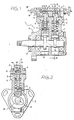
- an in-line injection pump for fuel injection systems for diesel engines with electrically controlled injectors is generally indicated 1.
- the pump 1 comprises essentially a base 2 which is normally of aluminium and is provided at one end with a substantially triangular attachment flange 3, and a head 4, normally of steel, which is separate from the base 2 and is fixed to its top by means of screws 5.
- each in-line pumping unit 6 includes, in generally known manner, a tappet 7 driven by a cam-shaft 8 for driving a piston 9.
- Each piston 9 is reciprocable within a respective cylinder 10 formed in an insert 11 carried by the head 4 and extending into an upper zone of the base 2.
- Each tappet 7 cooperates operatively with a respective cam 12 of the shaft 8 which, as illustrated in greater detail in Figure 2, has a double-lobed profile.
- Each cylinder 10 is associated with an intake valve 13 and a delivery valve 14 of generally known type.
- the two intake valves 13 are connected to a common passage 15 formed in the head 4 and communicating with an inlet connector 16 fitted to one side thereof, whilst the two delivery valves 14 are connected to a common passage 17 parallel to the passage 15 and com municating with a delivery connector 18 carried by the opposite side of the head 4.
- the high-pressure side of the pump is located entirely within the head 4, with an obvious rationalisation and simplification of the construction of the pump.
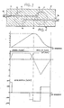
- Figure 4 illustrates several functional graphs of the pump according to the invention, resulting from the particular profile of the cams 12 which are designed so as to achieve constant accelerations with trapezoidal-asymmetric-type changes in the velocity of the pistons 9. Suitable staggering of the cams 12 gives a low-pressure ripple at the outlet, with minimised dead volumes, since the overlapping of delivery of the pumping units allows accomplishment of constant flow rate over the 360° of rotation of the pump.
- the graphs of Figure 4 relate in particular to the pump according to the invention, which is dimensioned as follows: - total swept volume: 0.4 - 0.6 cm3 /revolution - maximum velocity: 2800 revolutions per minute - base radius of the cams 12: 14.5mm - roll radius of the tappet 7: 8.5mm - maximum rise: 6 mm.
- the three graphs of Figure 4 show, in dependence on the angular position of the cams 12, the rise, the velocity and the acceleration of the pistons 9, respectively.
Landscapes
- Engineering & Computer Science (AREA)
- Mechanical Engineering (AREA)
- General Engineering & Computer Science (AREA)
- Chemical & Material Sciences (AREA)
- Combustion & Propulsion (AREA)
- Fuel-Injection Apparatus (AREA)
Applications Claiming Priority (2)
| Application Number | Priority Date | Filing Date | Title |
|---|---|---|---|
| IT67732/87A IT1217254B (it) | 1987-08-25 | 1987-08-25 | Pompa in linea per impianti di iniezione del combustibile con iniettori comandati per motori a ciclo diesel |
| IT6773287 | 1987-08-25 |
Publications (1)
| Publication Number | Publication Date |
|---|---|
| EP0304741A1 true EP0304741A1 (fr) | 1989-03-01 |
Family
ID=11304859
Family Applications (1)
| Application Number | Title | Priority Date | Filing Date |
|---|---|---|---|
| EP88113139A Withdrawn EP0304741A1 (fr) | 1987-08-25 | 1988-08-12 | Pompe en ligne pour systèmes d'injection de combustible à injecteurs commandés pour moteurs à combustion interne |
Country Status (4)
| Country | Link |
|---|---|
| EP (1) | EP0304741A1 (fr) |
| JP (1) | JPH01267356A (fr) |
| BR (1) | BR8804303A (fr) |
| IT (1) | IT1217254B (fr) |
Cited By (9)
| Publication number | Priority date | Publication date | Assignee | Title |
|---|---|---|---|---|
| EP0453227A1 (fr) * | 1990-04-20 | 1991-10-23 | Zexel Corporation | Pompe d'injection de combustible |
| EP0629777A1 (fr) * | 1993-06-18 | 1994-12-21 | Yamaha Hatsudoki Kabushiki Kaisha | Système d'injection de combustible |
| WO1999037910A1 (fr) * | 1998-01-23 | 1999-07-29 | Robert Bosch Gmbh | Systeme de pompes pour alimentation en carburant sous haute pression |
| EP0856661A3 (fr) * | 1997-01-30 | 2000-01-26 | Lucas Industries Limited | Pompe de carburant |
| EP1072787A2 (fr) † | 1999-07-28 | 2001-01-31 | Toyota Jidosha Kabushiki Kaisha | Pompe à carburant à haute pression et came pour pompe à carburant à haute pression |
| EP1270929A1 (fr) * | 2000-03-14 | 2003-01-02 | Bosch Automotive Systems Corporation | Pompe a combustible et dispositif d'alimentation en combustible utilisant cette pompe |
| EP1655480A1 (fr) * | 2004-11-04 | 2006-05-10 | Robert Bosch Gmbh | Procédé pour utiliser un système de carburant d'un moteur à combustion interne et systéme de carburant |
| JP2017529487A (ja) * | 2014-10-09 | 2017-10-05 | ローベルト ボッシュ ゲゼルシャフト ミット ベシュレンクテル ハフツング | 燃料、好ましくはディーゼル油を内燃機関に供給するためのポンプユニット |
| DE102017102589A1 (de) | 2017-02-09 | 2018-08-09 | Volkswagen Ag | Verbrennungsmotor |
Citations (4)
| Publication number | Priority date | Publication date | Assignee | Title |
|---|---|---|---|---|
| GB365061A (en) * | 1930-10-11 | 1932-01-11 | Superior Engine Company Inc | Improvements in or relating to fuel pumps |
| US2440194A (en) * | 1946-01-29 | 1948-04-20 | Texas Co | Fuel pump |
| US2845875A (en) * | 1956-03-29 | 1958-08-05 | Thomas H Corbett | Pumps |
| DE1297479B (de) * | 1968-02-28 | 1969-06-12 | Brueckner Alfred | Zylinderkopf einer Hochdruckkolbenpumpe fuer Fluessigkeiten |
-
1987
- 1987-08-25 IT IT67732/87A patent/IT1217254B/it active
-
1988
- 1988-08-12 EP EP88113139A patent/EP0304741A1/fr not_active Withdrawn
- 1988-08-24 BR BR8804303A patent/BR8804303A/pt unknown
- 1988-08-25 JP JP63209631A patent/JPH01267356A/ja active Pending
Patent Citations (4)
| Publication number | Priority date | Publication date | Assignee | Title |
|---|---|---|---|---|
| GB365061A (en) * | 1930-10-11 | 1932-01-11 | Superior Engine Company Inc | Improvements in or relating to fuel pumps |
| US2440194A (en) * | 1946-01-29 | 1948-04-20 | Texas Co | Fuel pump |
| US2845875A (en) * | 1956-03-29 | 1958-08-05 | Thomas H Corbett | Pumps |
| DE1297479B (de) * | 1968-02-28 | 1969-06-12 | Brueckner Alfred | Zylinderkopf einer Hochdruckkolbenpumpe fuer Fluessigkeiten |
Non-Patent Citations (1)
| Title |
|---|
| V.A. VANSCHEIDT: "Design and strength calculations of marine diesel engines", 1969, pages 365-370, Soudostroenie, Leningrad, SU * |
Cited By (15)
| Publication number | Priority date | Publication date | Assignee | Title |
|---|---|---|---|---|
| EP0453227A1 (fr) * | 1990-04-20 | 1991-10-23 | Zexel Corporation | Pompe d'injection de combustible |
| US5165851A (en) * | 1990-04-20 | 1992-11-24 | Zexel Corporation | Fuel injection pump |
| EP0629777A1 (fr) * | 1993-06-18 | 1994-12-21 | Yamaha Hatsudoki Kabushiki Kaisha | Système d'injection de combustible |
| US5511956A (en) * | 1993-06-18 | 1996-04-30 | Yamaha Hatsudoki Kabushiki Kaisha | High pressure fuel pump for internal combustion engine |
| EP0856661A3 (fr) * | 1997-01-30 | 2000-01-26 | Lucas Industries Limited | Pompe de carburant |
| WO1999037910A1 (fr) * | 1998-01-23 | 1999-07-29 | Robert Bosch Gmbh | Systeme de pompes pour alimentation en carburant sous haute pression |
| EP1072787A2 (fr) † | 1999-07-28 | 2001-01-31 | Toyota Jidosha Kabushiki Kaisha | Pompe à carburant à haute pression et came pour pompe à carburant à haute pression |
| EP1072787B2 (fr) † | 1999-07-28 | 2010-02-24 | Toyota Jidosha Kabushiki Kaisha | Pompe à carburant à haute pression et came pour pompe à carburant à haute pression |
| EP1270929A1 (fr) * | 2000-03-14 | 2003-01-02 | Bosch Automotive Systems Corporation | Pompe a combustible et dispositif d'alimentation en combustible utilisant cette pompe |
| EP1270929A4 (fr) * | 2000-03-14 | 2004-08-18 | Bosch Automotive Systems Corp | Pompe a combustible et dispositif d'alimentation en combustible utilisant cette pompe |
| EP1655480A1 (fr) * | 2004-11-04 | 2006-05-10 | Robert Bosch Gmbh | Procédé pour utiliser un système de carburant d'un moteur à combustion interne et systéme de carburant |
| JP2017529487A (ja) * | 2014-10-09 | 2017-10-05 | ローベルト ボッシュ ゲゼルシャフト ミット ベシュレンクテル ハフツング | 燃料、好ましくはディーゼル油を内燃機関に供給するためのポンプユニット |
| US10107244B2 (en) | 2014-10-09 | 2018-10-23 | Robert Bosch Gmbh | Pump unit for supplying fuel, preferably diesel oil, to an internal combustion engine |
| DE102017102589A1 (de) | 2017-02-09 | 2018-08-09 | Volkswagen Ag | Verbrennungsmotor |
| DE102017102589B4 (de) | 2017-02-09 | 2021-08-19 | Volkswagen Ag | Verbrennungsmotor |
Also Published As
| Publication number | Publication date |
|---|---|
| JPH01267356A (ja) | 1989-10-25 |
| BR8804303A (pt) | 1989-03-21 |
| IT8767732A0 (it) | 1987-08-25 |
| IT1217254B (it) | 1990-03-22 |
Similar Documents
| Publication | Publication Date | Title |
|---|---|---|
| EP1072787B2 (fr) | Pompe à carburant à haute pression et came pour pompe à carburant à haute pression | |
| EP0914553B1 (fr) | Pompe de fluides avec soupape a commande par solenoide integree pour derivation | |
| EP0629777B1 (fr) | Système d'injection de combustible | |
| US6763808B2 (en) | Fuel pump and fuel feeding device using the fuel pump | |
| EP0304741A1 (fr) | Pompe en ligne pour systèmes d'injection de combustible à injecteurs commandés pour moteurs à combustion interne | |
| US8136508B2 (en) | Selective displacement control of multi-plunger fuel pump | |
| EP1557555B1 (fr) | Dispositif d'alimentation de carburant d'un moteur à combustion interne | |
| US7178509B2 (en) | High-pressure pump, in particular for a fuel injection system of an internal combustion engine | |
| JP2003314394A (ja) | 内燃機関に用いられる燃料噴射装置 | |
| US20080109152A1 (en) | Selective displacement control of multi-plunger fuel pump | |
| JP2690734B2 (ja) | 可変吐出量高圧ポンプ | |
| US4928656A (en) | Fuel-injection pump with variable cylinder capacity for diesel engine injection systems | |
| US20080115770A1 (en) | Pump with torque reversal avoidance feature and engine system using same | |
| US6817841B2 (en) | High-pressure fuel pump for internal combustion engine with improved partial-load performance | |
| CA2358444A1 (fr) | Moteur a deux temps | |
| JP2001511869A (ja) | 内燃機関の燃料噴射系における燃料供給用の高圧ポンプ | |
| GB2218161A (en) | A fuel injection pump for an internal combustion engine, having pre-injection and main injection | |
| US6807951B2 (en) | High-pressure fuel pump with integrated blocking-vane prefeed pump | |
| US6843641B1 (en) | Radial piston pump | |
| CN101205859A (zh) | 控制按需燃油泵的方法 | |
| US5784948A (en) | Positive displacement pump having levitating magnetic piston spring circuit | |
| EP1685325B1 (fr) | Pompe a carburant avec plusieurs cames | |
| JP2965032B1 (ja) | 内燃機関の燃料ポンプ | |
| EP1555432B1 (fr) | Pompe hydraulique | |
| GB1440818A (en) | Fuel injection pumps |
Legal Events
| Date | Code | Title | Description |
|---|---|---|---|
| PUAI | Public reference made under article 153(3) epc to a published international application that has entered the european phase |
Free format text: ORIGINAL CODE: 0009012 |
|
| AK | Designated contracting states |
Kind code of ref document: A1 Designated state(s): AT BE CH DE ES FR GB GR IT LI LU NL SE |
|
| 17P | Request for examination filed |
Effective date: 19890727 |
|
| 17Q | First examination report despatched |
Effective date: 19900410 |
|
| STAA | Information on the status of an ep patent application or granted ep patent |
Free format text: STATUS: THE APPLICATION IS DEEMED TO BE WITHDRAWN |
|
| 18D | Application deemed to be withdrawn |
Effective date: 19900821 |