EP1270924A2 - Ensemble intégré de collecteur d'admission pour un moteur à combustion interne - Google Patents
Ensemble intégré de collecteur d'admission pour un moteur à combustion interne Download PDFInfo
- Publication number
- EP1270924A2 EP1270924A2 EP02077218A EP02077218A EP1270924A2 EP 1270924 A2 EP1270924 A2 EP 1270924A2 EP 02077218 A EP02077218 A EP 02077218A EP 02077218 A EP02077218 A EP 02077218A EP 1270924 A2 EP1270924 A2 EP 1270924A2
- Authority
- EP
- European Patent Office
- Prior art keywords
- assembly
- valve
- manifold
- engine
- intake manifold
- Prior art date
- Legal status (The legal status is an assumption and is not a legal conclusion. Google has not performed a legal analysis and makes no representation as to the accuracy of the status listed.)
- Withdrawn
Links
- 238000002485 combustion reaction Methods 0.000 title claims description 7
- 230000001105 regulatory effect Effects 0.000 claims abstract description 11
- 239000002283 diesel fuel Substances 0.000 claims 1
- 230000001360 synchronised effect Effects 0.000 abstract description 2
- 230000009471 action Effects 0.000 description 5
- 239000000446 fuel Substances 0.000 description 4
- 230000006870 function Effects 0.000 description 4
- 230000007246 mechanism Effects 0.000 description 3
- 239000004071 soot Substances 0.000 description 3
- 230000008901 benefit Effects 0.000 description 2
- 230000006835 compression Effects 0.000 description 2
- 238000007906 compression Methods 0.000 description 2
- 238000004519 manufacturing process Methods 0.000 description 2
- 230000013011 mating Effects 0.000 description 2
- 229910000838 Al alloy Inorganic materials 0.000 description 1
- 230000000712 assembly Effects 0.000 description 1
- 238000000429 assembly Methods 0.000 description 1
- 230000002457 bidirectional effect Effects 0.000 description 1
- 238000010276 construction Methods 0.000 description 1
- 230000001276 controlling effect Effects 0.000 description 1
- 230000007797 corrosion Effects 0.000 description 1
- 238000005260 corrosion Methods 0.000 description 1
- 230000003247 decreasing effect Effects 0.000 description 1
- 238000004512 die casting Methods 0.000 description 1
- 230000009977 dual effect Effects 0.000 description 1
- 230000000694 effects Effects 0.000 description 1
- 238000010348 incorporation Methods 0.000 description 1
- 229910052751 metal Inorganic materials 0.000 description 1
- 239000002184 metal Substances 0.000 description 1
- 230000009467 reduction Effects 0.000 description 1
- 230000000717 retained effect Effects 0.000 description 1
- 238000007493 shaping process Methods 0.000 description 1
Images


Classifications
-
- F—MECHANICAL ENGINEERING; LIGHTING; HEATING; WEAPONS; BLASTING
- F02—COMBUSTION ENGINES; HOT-GAS OR COMBUSTION-PRODUCT ENGINE PLANTS
- F02D—CONTROLLING COMBUSTION ENGINES
- F02D9/00—Controlling engines by throttling air or fuel-and-air induction conduits or exhaust conduits
- F02D9/08—Throttle valves specially adapted therefor; Arrangements of such valves in conduits
- F02D9/12—Throttle valves specially adapted therefor; Arrangements of such valves in conduits having slidably-mounted valve members; having valve members movable longitudinally of conduit
-
- F—MECHANICAL ENGINEERING; LIGHTING; HEATING; WEAPONS; BLASTING
- F02—COMBUSTION ENGINES; HOT-GAS OR COMBUSTION-PRODUCT ENGINE PLANTS
- F02B—INTERNAL-COMBUSTION PISTON ENGINES; COMBUSTION ENGINES IN GENERAL
- F02B31/00—Modifying induction systems for imparting a rotation to the charge in the cylinder
- F02B31/04—Modifying induction systems for imparting a rotation to the charge in the cylinder by means within the induction channel, e.g. deflectors
- F02B31/06—Movable means, e.g. butterfly valves
-
- F—MECHANICAL ENGINEERING; LIGHTING; HEATING; WEAPONS; BLASTING
- F02—COMBUSTION ENGINES; HOT-GAS OR COMBUSTION-PRODUCT ENGINE PLANTS
- F02B—INTERNAL-COMBUSTION PISTON ENGINES; COMBUSTION ENGINES IN GENERAL
- F02B31/00—Modifying induction systems for imparting a rotation to the charge in the cylinder
- F02B31/08—Modifying induction systems for imparting a rotation to the charge in the cylinder having multiple air inlets
- F02B31/085—Modifying induction systems for imparting a rotation to the charge in the cylinder having multiple air inlets having two inlet valves
-
- F—MECHANICAL ENGINEERING; LIGHTING; HEATING; WEAPONS; BLASTING
- F02—COMBUSTION ENGINES; HOT-GAS OR COMBUSTION-PRODUCT ENGINE PLANTS
- F02M—SUPPLYING COMBUSTION ENGINES IN GENERAL WITH COMBUSTIBLE MIXTURES OR CONSTITUENTS THEREOF
- F02M26/00—Engine-pertinent apparatus for adding exhaust gases to combustion-air, main fuel or fuel-air mixture, e.g. by exhaust gas recirculation [EGR] systems
- F02M26/13—Arrangement or layout of EGR passages, e.g. in relation to specific engine parts or for incorporation of accessories
- F02M26/17—Arrangement or layout of EGR passages, e.g. in relation to specific engine parts or for incorporation of accessories in relation to the intake system
- F02M26/21—Arrangement or layout of EGR passages, e.g. in relation to specific engine parts or for incorporation of accessories in relation to the intake system with EGR valves located at or near the connection to the intake system
-
- F—MECHANICAL ENGINEERING; LIGHTING; HEATING; WEAPONS; BLASTING
- F02—COMBUSTION ENGINES; HOT-GAS OR COMBUSTION-PRODUCT ENGINE PLANTS
- F02M—SUPPLYING COMBUSTION ENGINES IN GENERAL WITH COMBUSTIBLE MIXTURES OR CONSTITUENTS THEREOF
- F02M26/00—Engine-pertinent apparatus for adding exhaust gases to combustion-air, main fuel or fuel-air mixture, e.g. by exhaust gas recirculation [EGR] systems
- F02M26/45—Sensors specially adapted for EGR systems
- F02M26/48—EGR valve position sensors
-
- F—MECHANICAL ENGINEERING; LIGHTING; HEATING; WEAPONS; BLASTING
- F02—COMBUSTION ENGINES; HOT-GAS OR COMBUSTION-PRODUCT ENGINE PLANTS
- F02M—SUPPLYING COMBUSTION ENGINES IN GENERAL WITH COMBUSTIBLE MIXTURES OR CONSTITUENTS THEREOF
- F02M26/00—Engine-pertinent apparatus for adding exhaust gases to combustion-air, main fuel or fuel-air mixture, e.g. by exhaust gas recirculation [EGR] systems
- F02M26/52—Systems for actuating EGR valves
- F02M26/53—Systems for actuating EGR valves using electric actuators, e.g. solenoids
- F02M26/54—Rotary actuators, e.g. step motors
-
- F—MECHANICAL ENGINEERING; LIGHTING; HEATING; WEAPONS; BLASTING
- F02—COMBUSTION ENGINES; HOT-GAS OR COMBUSTION-PRODUCT ENGINE PLANTS
- F02M—SUPPLYING COMBUSTION ENGINES IN GENERAL WITH COMBUSTIBLE MIXTURES OR CONSTITUENTS THEREOF
- F02M26/00—Engine-pertinent apparatus for adding exhaust gases to combustion-air, main fuel or fuel-air mixture, e.g. by exhaust gas recirculation [EGR] systems
- F02M26/52—Systems for actuating EGR valves
- F02M26/64—Systems for actuating EGR valves the EGR valve being operated together with an intake air throttle
-
- F—MECHANICAL ENGINEERING; LIGHTING; HEATING; WEAPONS; BLASTING
- F02—COMBUSTION ENGINES; HOT-GAS OR COMBUSTION-PRODUCT ENGINE PLANTS
- F02M—SUPPLYING COMBUSTION ENGINES IN GENERAL WITH COMBUSTIBLE MIXTURES OR CONSTITUENTS THEREOF
- F02M26/00—Engine-pertinent apparatus for adding exhaust gases to combustion-air, main fuel or fuel-air mixture, e.g. by exhaust gas recirculation [EGR] systems
- F02M26/65—Constructional details of EGR valves
- F02M26/66—Lift valves, e.g. poppet valves
- F02M26/67—Pintles; Spindles; Springs; Bearings; Sealings; Connections to actuators
-
- F—MECHANICAL ENGINEERING; LIGHTING; HEATING; WEAPONS; BLASTING
- F02—COMBUSTION ENGINES; HOT-GAS OR COMBUSTION-PRODUCT ENGINE PLANTS
- F02M—SUPPLYING COMBUSTION ENGINES IN GENERAL WITH COMBUSTIBLE MIXTURES OR CONSTITUENTS THEREOF
- F02M35/00—Combustion-air cleaners, air intakes, intake silencers, or induction systems specially adapted for, or arranged on, internal-combustion engines
- F02M35/10—Air intakes; Induction systems
- F02M35/10006—Air intakes; Induction systems characterised by the position of elements of the air intake system in direction of the air intake flow, i.e. between ambient air inlet and supply to the combustion chamber
- F02M35/10078—Connections of intake systems to the engine
- F02M35/10085—Connections of intake systems to the engine having a connecting piece, e.g. a flange, between the engine and the air intake being foreseen with a throttle valve, fuel injector, mixture ducts or the like
-
- F—MECHANICAL ENGINEERING; LIGHTING; HEATING; WEAPONS; BLASTING
- F02—COMBUSTION ENGINES; HOT-GAS OR COMBUSTION-PRODUCT ENGINE PLANTS
- F02M—SUPPLYING COMBUSTION ENGINES IN GENERAL WITH COMBUSTIBLE MIXTURES OR CONSTITUENTS THEREOF
- F02M35/00—Combustion-air cleaners, air intakes, intake silencers, or induction systems specially adapted for, or arranged on, internal-combustion engines
- F02M35/10—Air intakes; Induction systems
- F02M35/10209—Fluid connections to the air intake system; their arrangement of pipes, valves or the like
- F02M35/10222—Exhaust gas recirculation [EGR]; Positive crankcase ventilation [PCV]; Additional air admission, lubricant or fuel vapour admission
-
- F—MECHANICAL ENGINEERING; LIGHTING; HEATING; WEAPONS; BLASTING
- F02—COMBUSTION ENGINES; HOT-GAS OR COMBUSTION-PRODUCT ENGINE PLANTS
- F02M—SUPPLYING COMBUSTION ENGINES IN GENERAL WITH COMBUSTIBLE MIXTURES OR CONSTITUENTS THEREOF
- F02M35/00—Combustion-air cleaners, air intakes, intake silencers, or induction systems specially adapted for, or arranged on, internal-combustion engines
- F02M35/10—Air intakes; Induction systems
- F02M35/10242—Devices or means connected to or integrated into air intakes; Air intakes combined with other engine or vehicle parts
- F02M35/10255—Arrangements of valves; Multi-way valves
-
- F—MECHANICAL ENGINEERING; LIGHTING; HEATING; WEAPONS; BLASTING
- F02—COMBUSTION ENGINES; HOT-GAS OR COMBUSTION-PRODUCT ENGINE PLANTS
- F02M—SUPPLYING COMBUSTION ENGINES IN GENERAL WITH COMBUSTIBLE MIXTURES OR CONSTITUENTS THEREOF
- F02M35/00—Combustion-air cleaners, air intakes, intake silencers, or induction systems specially adapted for, or arranged on, internal-combustion engines
- F02M35/10—Air intakes; Induction systems
- F02M35/10242—Devices or means connected to or integrated into air intakes; Air intakes combined with other engine or vehicle parts
- F02M35/10288—Air intakes combined with another engine part, e.g. cylinder head cover or being cast in one piece with the exhaust manifold, cylinder head or engine block
-
- F—MECHANICAL ENGINEERING; LIGHTING; HEATING; WEAPONS; BLASTING
- F02—COMBUSTION ENGINES; HOT-GAS OR COMBUSTION-PRODUCT ENGINE PLANTS
- F02M—SUPPLYING COMBUSTION ENGINES IN GENERAL WITH COMBUSTIBLE MIXTURES OR CONSTITUENTS THEREOF
- F02M35/00—Combustion-air cleaners, air intakes, intake silencers, or induction systems specially adapted for, or arranged on, internal-combustion engines
- F02M35/10—Air intakes; Induction systems
- F02M35/1034—Manufacturing and assembling intake systems
- F02M35/10354—Joining multiple sections together
-
- F—MECHANICAL ENGINEERING; LIGHTING; HEATING; WEAPONS; BLASTING
- F02—COMBUSTION ENGINES; HOT-GAS OR COMBUSTION-PRODUCT ENGINE PLANTS
- F02M—SUPPLYING COMBUSTION ENGINES IN GENERAL WITH COMBUSTIBLE MIXTURES OR CONSTITUENTS THEREOF
- F02M35/00—Combustion-air cleaners, air intakes, intake silencers, or induction systems specially adapted for, or arranged on, internal-combustion engines
- F02M35/10—Air intakes; Induction systems
- F02M35/104—Intake manifolds
- F02M35/108—Intake manifolds with primary and secondary intake passages
- F02M35/1085—Intake manifolds with primary and secondary intake passages the combustion chamber having multiple intake valves
-
- F—MECHANICAL ENGINEERING; LIGHTING; HEATING; WEAPONS; BLASTING
- F02—COMBUSTION ENGINES; HOT-GAS OR COMBUSTION-PRODUCT ENGINE PLANTS
- F02M—SUPPLYING COMBUSTION ENGINES IN GENERAL WITH COMBUSTIBLE MIXTURES OR CONSTITUENTS THEREOF
- F02M35/00—Combustion-air cleaners, air intakes, intake silencers, or induction systems specially adapted for, or arranged on, internal-combustion engines
- F02M35/10—Air intakes; Induction systems
- F02M35/104—Intake manifolds
- F02M35/112—Intake manifolds for engines with cylinders all in one line
-
- F—MECHANICAL ENGINEERING; LIGHTING; HEATING; WEAPONS; BLASTING
- F02—COMBUSTION ENGINES; HOT-GAS OR COMBUSTION-PRODUCT ENGINE PLANTS
- F02B—INTERNAL-COMBUSTION PISTON ENGINES; COMBUSTION ENGINES IN GENERAL
- F02B3/00—Engines characterised by air compression and subsequent fuel addition
- F02B3/06—Engines characterised by air compression and subsequent fuel addition with compression ignition
-
- F—MECHANICAL ENGINEERING; LIGHTING; HEATING; WEAPONS; BLASTING
- F02—COMBUSTION ENGINES; HOT-GAS OR COMBUSTION-PRODUCT ENGINE PLANTS
- F02D—CONTROLLING COMBUSTION ENGINES
- F02D9/00—Controlling engines by throttling air or fuel-and-air induction conduits or exhaust conduits
- F02D9/02—Controlling engines by throttling air or fuel-and-air induction conduits or exhaust conduits concerning induction conduits
- F02D2009/0201—Arrangements; Control features; Details thereof
- F02D2009/0205—Arrangements; Control features; Details thereof working on the throttle valve and another valve, e.g. choke
-
- F—MECHANICAL ENGINEERING; LIGHTING; HEATING; WEAPONS; BLASTING
- F02—COMBUSTION ENGINES; HOT-GAS OR COMBUSTION-PRODUCT ENGINE PLANTS
- F02D—CONTROLLING COMBUSTION ENGINES
- F02D9/00—Controlling engines by throttling air or fuel-and-air induction conduits or exhaust conduits
- F02D9/02—Controlling engines by throttling air or fuel-and-air induction conduits or exhaust conduits concerning induction conduits
- F02D2009/0201—Arrangements; Control features; Details thereof
- F02D2009/024—Increasing intake vacuum
-
- F—MECHANICAL ENGINEERING; LIGHTING; HEATING; WEAPONS; BLASTING
- F02—COMBUSTION ENGINES; HOT-GAS OR COMBUSTION-PRODUCT ENGINE PLANTS
- F02D—CONTROLLING COMBUSTION ENGINES
- F02D9/00—Controlling engines by throttling air or fuel-and-air induction conduits or exhaust conduits
- F02D9/02—Controlling engines by throttling air or fuel-and-air induction conduits or exhaust conduits concerning induction conduits
- F02D2009/0201—Arrangements; Control features; Details thereof
- F02D2009/0276—Throttle and EGR-valve operated together
-
- F—MECHANICAL ENGINEERING; LIGHTING; HEATING; WEAPONS; BLASTING
- F02—COMBUSTION ENGINES; HOT-GAS OR COMBUSTION-PRODUCT ENGINE PLANTS
- F02D—CONTROLLING COMBUSTION ENGINES
- F02D9/00—Controlling engines by throttling air or fuel-and-air induction conduits or exhaust conduits
- F02D9/02—Controlling engines by throttling air or fuel-and-air induction conduits or exhaust conduits concerning induction conduits
- F02D2009/0201—Arrangements; Control features; Details thereof
- F02D2009/0288—Throttle control device specially adapted for spark-assisted compression-ignition engine (Diesel engine)
-
- F—MECHANICAL ENGINEERING; LIGHTING; HEATING; WEAPONS; BLASTING
- F02—COMBUSTION ENGINES; HOT-GAS OR COMBUSTION-PRODUCT ENGINE PLANTS
- F02M—SUPPLYING COMBUSTION ENGINES IN GENERAL WITH COMBUSTIBLE MIXTURES OR CONSTITUENTS THEREOF
- F02M35/00—Combustion-air cleaners, air intakes, intake silencers, or induction systems specially adapted for, or arranged on, internal-combustion engines
- F02M35/10—Air intakes; Induction systems
- F02M35/1015—Air intakes; Induction systems characterised by the engine type
- F02M35/10157—Supercharged engines
-
- Y—GENERAL TAGGING OF NEW TECHNOLOGICAL DEVELOPMENTS; GENERAL TAGGING OF CROSS-SECTIONAL TECHNOLOGIES SPANNING OVER SEVERAL SECTIONS OF THE IPC; TECHNICAL SUBJECTS COVERED BY FORMER USPC CROSS-REFERENCE ART COLLECTIONS [XRACs] AND DIGESTS
- Y02—TECHNOLOGIES OR APPLICATIONS FOR MITIGATION OR ADAPTATION AGAINST CLIMATE CHANGE
- Y02T—CLIMATE CHANGE MITIGATION TECHNOLOGIES RELATED TO TRANSPORTATION
- Y02T10/00—Road transport of goods or passengers
- Y02T10/10—Internal combustion engine [ICE] based vehicles
- Y02T10/12—Improving ICE efficiencies
Definitions
- the present invention relates to systems and apparatus for managing gas flow through internal combustion engines; more particularly, to one or more valving devices associated with the intake manifold of an internal combustion engine; and most particularly, to an intake manifold assembly for an internal combustion engine, such as a diesel engine or a variable valve lift gasoline engine, wherein an exhaust gas recirculation valve, a manifold vacuum control valve, and other gas-control valves as may be necessary, are integrated into the assembly.
- a conventional gasoline-powered engine includes a throttle valve at the inlet to the intake manifold to control the flow of air into the engine and thereby to regulate the speed of the engine.
- Such throttling of the inlet variably creates a subatmospheric condition in the manifold.
- Recirculation of exhaust gas into the intake manifold uses a pressure drop between the exhaust manifold and the intake manifold to draw exhaust gas into the intake manifold. Such a pressure drop is virtually non-existent in an unmodified diesel engine and also in a gasoline engine wherein gas flow is controlled by varying the lift of the intake valves.
- a rotary butterfly-type valve It is known to create manifold vacuum in a diesel intake manifold by providing an air control valve at the manifold inlet, typically a rotary butterfly-type valve.
- a valve is typically actuated by an electric motor and gear train or a stepper motor and is provided as a subassembly which must be attached to the manifold as by bolting and which requires its own power and control connections in a wiring harness.
- a rotary butterfly valve has a highly non-linear flow profile as a function of valve angle; is difficult to close completely without jamming; and typically passes significant air flow in the "closed" position.
- EGR valve exhaust gas recirculation
- Prior art EGR valves provide exhaust gas globally to the interior of the intake manifold which then distributes the gas along with intake air via runners to the individual cylinders.
- each diesel cylinder it is further known to provide dual intake ports to each diesel cylinder, one such port being open at all times and the other such port being closable by a butterfly-type valve.
- the ports are off-axis of the cylinders such that when the valves are closed, as under low engine load conditions, air entering the cylinder is swirled advantageously to center the fuel charge in the cylinder.
- the individual valves are actuated by, for example, electrically-powered rotary actuators similar to that known for a throttle valve.
- an integrated intake manifold assembly in accordance with the invention includes a poppet manifold vacuum regulating valve (MVR valve) disposed at the air inlet to the manifold to regulate air flow into the manifold; a poppet EGR valve disposed on the manifold to regulate exhaust gas flow into the air intake system; and a bidirectional camshaft and cams for operating simultaneously the MVR valve and the EGR valve.
- the valve bodies are integrally formed in the wall of the intake manifold.
- the camshaft is driven by a single brush DC motor and gear train.
- the cams are arranged on the shaft to provide optimum synchronized opening and closing of the related valves.
- the cams may also be individually shaped as needed to optimize the actuation profile of each valve.
- the assembly may further include a swirl valve plate disposed between the manifold and the engine head and having a plurality of ganged swirl valves actuated by linkage connected to the camshaft for coordinated motion with the MVR and EGR valves.
- the swirl valve plate is also ported as a distribution rail to receive exhaust gas from the EGR valve and distribute it to the individual cylinders, bypassing altogether the interior of the intake manifold and obviating soot deposits in the manifold.
- the valve stems of the MVR and EGR valves are modified as forked yokes which engage the camshaft as reciprocating struts to minimize side loading of the valve stems by the rotary action of the cams.
- An integrated intake manifold assembly in accordance with the invention when compared to prior art assemblies of stand-alone components, eliminates eight bolts and two gaskets; eliminates two actuators and related wiring; eliminates vacuum actuation and hoses; reduces soot in the air intake system, protecting air components; reduces electrical connections to two; simplifies manufacture and assembly; and reduces the overall size and mass of the air control system.
- the embodiment is assumed to be oriented such that an associated engine is beside, and an exhaust manifold below, the embodiment.
- the use of the terms up, down, upper, lower, above, and below assume such an orientation.
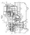
- an integrated intake manifold assembly 10 in accordance with the invention includes an intake manifold element 12 preferably formed as by die casting of metal such as aluminum alloy.
- Formed integrally with element 12 are a first housing 14 for a MVR valve assembly 16; a second housing 18 for an EGR valve assembly 20; a third housing 22 for a drive motor (not visible in these drawings); a fourth housing 24 for a gear train (also not visible); a fifth housing 26 for a lever actuator 28 attached to a camshaft 82; a first mounting flange 30 for attaching assembly 10 to an engine block or head 32; a second mounting flange 34 for attaching assembly 10 to an exhaust manifold 36; and a receptacle 38 for mounting of a manifold vacuum sensor 40 having an electrical connector 42 for conventional connection to an engine control module (ECM) (not shown).
- ECM engine control module
- MVR valves and EGR valves are assembled onto a manifold and require independent electrical actuation, position sensing, and control
- present MVR and EGR valves are integrally formed into the manifold itself and mechanically actuated by a common camshaft, as described further below.
- a swirl valve plate 44 Attached to, but separate from, integrated intake manifold assembly 10 is a swirl valve plate 44 disposed between assembly 10 and engine 32.
- Plate 44 includes first ports 46, for distributing air from manifold 12 into each of four engine cylinders (not shown) under low engine load, and second ports 48 in flow parallel with first ports 46 for providing additional air under high load conditions. Air flow from manifold 12 through second ports 48 may be regulated by swirl control valves 50 which are ganged for unified action by being mounted on a single control shaft 52 extending through axially aligned bores 54 in plate 44.
- a link 56 connects first lever actuator 28 with a similar second lever actuator 58 (FIGS. 8, 18, and 19) attached to shaft 52.
- valves 50 When valves 50 are closed, air is introduced tangentially to the cylinders only via ports 46, causing a swirling motion which tends to desirably center the fuel charge on the piston. Under high air and fuel volumes, when valves 50 are open, such swirling is unimportant and is eliminated.
- Such linkage may be attached to actuator 28 either above the axis of rotation, as shown for example in FIGS. 1, 2, 5, and 16-19, or below the axis of rotation, as shown in FIG. 8.
- the arrangement shown in FIG. 8 allows for the actuation of a swirl-port system with no linkages external to the intake manifold. All of the components of this mechanism thus may be hidden internally, within the intake manifold and swirl plate, by appropriately configuring the manifold. After the assembly is mounted to the engine, all moving parts are concealed and protected from the environment, providing a safe, robust assembly.
- plate 44 is also provided with a longitudinal channel 60 matable with a similar channel 62 formed in assembly 10 to form an exhaust gas distribution rail 64 supplied with exhaust gas via an exhaust gas conduit 66 from EGR valve assembly 20.
- Rail 64 is connected via individual runners (not visible) to each of first ports 46 for dispensing exhaust gas into each of the cylinders of engine 32.
- This arrangement thus accomplishes controlled exhaust gas recirculation to the cylinders without exposing the interior of the intake manifold to soot and corrosive oxides.
- an integrated EGR valve assembly 20 in accordance with the invention may simply feed exhaust gas via a conduit 66' analogous to conduit 66 directly into intake manifold 12 for distribution with air into the cylinders, as in the prior art.
- the swirl plate is not needed and distribution of EGR to the individual cylinders is not required, in which case assembly 10 is mounted directly onto engine 32, and conduit 66' represents the preferred embodiment.
- valve assembly 16 may function as a manifold vacuum regulating valve, substantially as in a diesel engine as described herein.
- an integrated intake manifold assembly in accordance with the invention may be usefully adapted for conventional throttle control by valve assembly 16.
- the mechanism 68 of the invention is housed in the various integrated housings formed in manifold 12, as recited above.
- the power train is a conventional motor and reduction gear train.
- a single brush DC motor 70 housed in third housing 22, is provided with a first pinion gear 72 which meshes with first ring gear 74 mounted on an idle shaft 76.
- Second pinion gear 78 attached to first ring gear 74, meshes with second ring gear 80 which is mounted on camshaft 82 via an output spring 84.
- a camshaft position sensor 79 is disposed on the proximal end 81 of camshaft 82.
- the gear train and position sensor are housed in a cover 83 boltable to the intake manifold.
- An electrical connector 85 provides power and operating signals to the motor and carries information from position sensor 79 to the ECM.
- Camshaft 82 is journalled in three sets of ball bearings 87 retained in bearing mounts formed in intake manifold 12.
- MVR cam 86 and EGR cam 88 having throughbores, are mounted on camshaft 82 at predetermined axial locations and at a predetermined angular relationship to each other. After the cams have been properly positioned during assembly, they are fixed in place by set screws 90. Preferably, after assembly and testing, the cams are drilled and pinned 91 to the camshaft.
- manifold vacuum regulating valve assembly 16 includes a poppet valve head 92 for mating with seat 94 formed integrally with manifold 12.
- Seat 94 is formed in a bore 96 defining an air inlet to manifold 12.
- a valve pintle 98 extends from the underside of head 92 and is received in a pintle bearing insert 100 disposed in a cylindrical boss 102 formed in manifold 12 for guiding the pintle and head during actuation of the valve.
- a return spring 104 surrounds boss 102 and is seated against a step in boss 102 for urging head 92 toward seat 94, to a normally-closed position.
- Valve head 92 is further provided with a slot and transverse bore for receiving a roller 106 and pin 107 for following the surface of MVR cam 86.
- MVR valve assembly 16 is shown in the open position, permitting the passage of air through inlet bore 96 into intake manifold 12.
- spring 104 is selected and the valve head and seat are constructed such that assembly 16 is fully closed when the engine is shut down. This prevents entry of additional air into the engine, important for some gasoline engines in preventing the well-known "diesel" effect of continued compressive running after the ignition is off. Prior art butterfly-type manifold entry valves are incapable of providing this advantage.
- the spring strength of spring 104 is preferably selected such that, in the event of valve control failure, the valve can be forced open by air compressed by a diesel supercharger and the engine can continue to run although non-optimally.
- exhaust gas recirculation valve assembly 20 includes a poppet valve head 108 for mating with seat 110 inserted into a step 112 in a bell-shaped valve body 114 formed integrally with manifold 12.
- Body 114 terminates at its lower end in flange 34, as recited above, for mounting onto exhaust manifold 36.
- a valve pintle 116 extends through head 108 and is secured thereto by nut 109, which sets the tolerance stack-up in the valve assembly. Further, pintle 116 extends from the upper side of head 108 and is received in a stepped bore 118 formed in manifold 12 for guiding the pintle and head during actuation of the valve.
- a return spring 120 surrounds pintle 116 and is captured between a pintle bearing insert 122 and an annular flange 124 on pintle 116 for urging head 108 toward seat 110, to a normally-closed position.
- the upper end of pintle 116 is further provided with a slot and transverse bore for receiving a roller 126 and pin 127 for following the surface of EGR cam 88.
- first conduit 66 connects EGR valve assembly 20 to exhaust gas rail 64. In FIGS. 5, 6, and 10, EGR valve assembly 20 is shown in the closed position, preventing the passage of exhaust gas through flange 34 into exhaust gas rail 64.
- EGR cam 88 is provided with a hook portion 128 which engages and captures roller 126 when cam 88 is rotated sufficiently counterclockwise, thereby mechanically locking assembly 20 in a closed position.
- each of valve heads 92,108 preferably is provided with a yoke element 130 extending from the valve head toward camshaft 82 and terminating in flat fork tines 132 which embrace the camshaft and are closely fitted against their respective cam lobes 86,88.
- additional stiffness of the tines may be obtained by connecting the tines with a strap 134, as shown in FIG. 11.
- the tines thus provide lateral support to the valve pintles 98,116 at their upper ends and thereby relieve side loading of the pintles by the rotary action of the cam lobes. This reduces wear on the pintles and increases the working life and reliability of the valves.
- FIG. 15 shows the operation of an integrated intake manifold assembly in accordance with the invention.
- Exemplary actuation curves for the swirl valve shaft 52, MVR valve 16, and EGR valve 20 are shown for a typical diesel engine application. Also refer to FIGS. 16 through 19 wherein the accompanying action of the swirl valve control subassembly 138 is shown.
- Relative valve position is shown in FIG. 15 as a function of camshaft position. Arbitrarily, the curves represent full engine speed at the far left (270° of camshaft rotation) and engine shutdown at the far right (0° of camshaft rotation).
- the swirl valves 50 (FIG. 16) and the MVR are fully open. There is no exhaust gas recirculation.
- the EGR valve is both closed and locked shut by hook 128 to prevent its being forced open by high intake manifold pressures from the engine turbocharger which would limit the effectiveness of the turbocharger.
- first lever actuator 28 has an arcuate slotted opening 136 for connection to link 56, the camshaft and swirl control body 140 are able to rotate counterclockwise sufficiently (about 20°) to unlock the EGR valve before link 56 becomes engaged in controlling the swirl valves.
- First torsion spring 142 is disposed in torsional compression on body 140 between notch 144 and pin extension 146 (see also FIG. 5), thus urging link 56 toward the valve-closed position shown in FIGS. 16 and 17.
- Second torsion spring 148 is also disposed in torsional compression on body 140 between lever actuator 28 and a recess in manifold 12 (not shown) but is counter-wound from spring 142. Spring 148 urges actuator 28 counterclockwise as seen in FIGS. 16-19 (springs omitted or partially omitted in FIGS. 17-19 for clarity).
- Camshaft 82 is provided with a radial tang 150 which can engage an axial tang 152 extending from body 140. In the 0° camshaft position shown in FIG. 16, body 140 and actuator 28 are are rotated by the camshaft such that the EGR valve is both closed and locked shut by hook 128, as shown in FIG. 10.
- first lever actuator 28 has arcuate slotted opening 136 for connection to link 56, the camshaft is able to rotate clockwise sufficiently to unlock the EGR valve without beginning to close the swirl valves, as shown in FIG. 17.
- Link 56 becomes engaged by actuator 28 at the right end of slot 136.
- link 56 is drawn counterclockwise by actuating lever 28, closing the swirl valves completely, as shown in FIG. 18, and the engine thus becomes supplied with air solely through first ports 46 (FIG. 2).
- the link is now prevented by the closing of the swirl valves from traveling farther, so further rotation of body 140 is prevented; the camshaft, however, may continue to be rotated within body 140, as body 140 is rotatably disposed on sealed bearings 141 (FIG. 6) mounted on camshaft 82.
- tang 150 separates from tang 152, as shown in FIG. 19.
- the EGR valve begins to open, adding exhaust gas to the air entering the cylinders.
- the MVR valve remains wide open until about 90° of rotation, then begins to close. Because the MVR valve is a poppet valve rather than a conventional rotary butterfly valve, the open area of the valve is linear with respect to pintle motion, and the slope of the curve is readily controlled by appropriately shaping the MVR cam lobe.
- the normal operating range of the engine is typically between cam positions of about 100° and 150°. Beyond about 180°, the MVR valve is fully closed (no fresh air is being admitted to the engine) and the EGR valve is fully open. Such a condition may be useful during non-combustive periods, such as going downhill, when fuel is withheld from the cylinders and recirculation of stale exhaust gas can progressively cool the engine cylinders.
- the camshaft is rotated to about 270° to the position shown in FIG. 19 and the swirl, MVR, and EGR valves are closed.
- the camshaft is automatically rotated clockwise through a predetermined angle to provide optimal opening settings for the MVR and EGR valves, the swirl valves remaining closed until high engine speed is again required.
- camshaft positions are programmed into a conventional engine control module in known fashion, which module receives various engine inputs including manifold pressure signals from sensor 40 and cam position signals from sensor 79.
- the ECM controls the action of motor 70 responsive to these and other signals and algorithms stored therein.
Landscapes
- Engineering & Computer Science (AREA)
- Chemical & Material Sciences (AREA)
- Combustion & Propulsion (AREA)
- Mechanical Engineering (AREA)
- General Engineering & Computer Science (AREA)
- Analytical Chemistry (AREA)
- Manufacturing & Machinery (AREA)
- Exhaust-Gas Circulating Devices (AREA)
- Valve Device For Special Equipments (AREA)
- Output Control And Ontrol Of Special Type Engine (AREA)
- Mechanically-Actuated Valves (AREA)
Applications Claiming Priority (2)
| Application Number | Priority Date | Filing Date | Title |
|---|---|---|---|
| US30173401P | 2001-06-28 | 2001-06-28 | |
| US301734P | 2001-06-28 |
Publications (2)
| Publication Number | Publication Date |
|---|---|
| EP1270924A2 true EP1270924A2 (fr) | 2003-01-02 |
| EP1270924A3 EP1270924A3 (fr) | 2004-01-07 |
Family
ID=23164632
Family Applications (5)
| Application Number | Title | Priority Date | Filing Date |
|---|---|---|---|
| EP02077218A Withdrawn EP1270924A3 (fr) | 2001-06-28 | 2002-06-06 | Ensemble intégré de collecteur d'admission pour un moteur à combustion interne |
| EP02077245A Expired - Lifetime EP1270898B1 (fr) | 2001-06-28 | 2002-06-10 | Système de canaux de tourbillonement pour moteur à combustion interne Diesel |
| EP02077242A Expired - Fee Related EP1270920B1 (fr) | 2001-06-28 | 2002-06-10 | Culbuteur pour soupape actionnée par came dans un système d'admission d'un moteur à combustion interne |
| EP02077243A Pending EP1270897A3 (fr) | 2001-06-28 | 2002-06-10 | Soupape à siège plan avec joug d'alignement |
| EP02077244A Withdrawn EP1270905A3 (fr) | 2001-06-28 | 2002-06-10 | Soupape d'admission à réponse linéaire |
Family Applications After (4)
| Application Number | Title | Priority Date | Filing Date |
|---|---|---|---|
| EP02077245A Expired - Lifetime EP1270898B1 (fr) | 2001-06-28 | 2002-06-10 | Système de canaux de tourbillonement pour moteur à combustion interne Diesel |
| EP02077242A Expired - Fee Related EP1270920B1 (fr) | 2001-06-28 | 2002-06-10 | Culbuteur pour soupape actionnée par came dans un système d'admission d'un moteur à combustion interne |
| EP02077243A Pending EP1270897A3 (fr) | 2001-06-28 | 2002-06-10 | Soupape à siège plan avec joug d'alignement |
| EP02077244A Withdrawn EP1270905A3 (fr) | 2001-06-28 | 2002-06-10 | Soupape d'admission à réponse linéaire |
Country Status (3)
| Country | Link |
|---|---|
| US (5) | US6571782B2 (fr) |
| EP (5) | EP1270924A3 (fr) |
| DE (2) | DE60205066T2 (fr) |
Cited By (1)
| Publication number | Priority date | Publication date | Assignee | Title |
|---|---|---|---|---|
| CN110662896A (zh) * | 2017-05-23 | 2020-01-07 | 怡来汽车电子底盘系统有限公司 | 一体型背压及egr阀模块 |
Families Citing this family (98)
| Publication number | Priority date | Publication date | Assignee | Title |
|---|---|---|---|---|
| AU2001259388B2 (en) * | 2000-05-03 | 2005-05-05 | Hanon Systems | EGR valve apparatus |
| EP1270924A3 (fr) | 2001-06-28 | 2004-01-07 | Delphi Technologies, Inc. | Ensemble intégré de collecteur d'admission pour un moteur à combustion interne |
| DE10217695A1 (de) * | 2002-04-20 | 2003-11-13 | Daimler Chrysler Ag | Verfahren zum erleichterten Starten einer Brennkraftmaschine |
| US6866020B2 (en) * | 2002-06-12 | 2005-03-15 | Delphi Technologies, Inc. | Vacuum management system for engine with variable valve lift |
| US6863048B2 (en) | 2002-06-12 | 2005-03-08 | Delphi Technologies, Inc. | Vacuum system for engine with variable valve lift |
| US6962138B2 (en) * | 2002-09-06 | 2005-11-08 | Delphi Technologies, Inc. | Throttle control for a small engine |
| JP4015528B2 (ja) * | 2002-10-21 | 2007-11-28 | 愛三工業株式会社 | 内燃機関の排気還流装置 |
| US20040165798A1 (en) * | 2003-02-26 | 2004-08-26 | Valdespino Jorge A. | Eccentric bearing for a poppet drive system |
| EP1457651A2 (fr) * | 2003-03-10 | 2004-09-15 | Hitachi, Ltd. | Dispositif d'alimentation en mélange air-carburant pour moteur à combustion interne |
| US8120023B2 (en) | 2006-06-05 | 2012-02-21 | Udt Sensors, Inc. | Low crosstalk, front-side illuminated, back-side contact photodiode array |
| US7880258B2 (en) * | 2003-05-05 | 2011-02-01 | Udt Sensors, Inc. | Thin wafer detectors with improved radiation damage and crosstalk characteristics |
| US7057254B2 (en) | 2003-05-05 | 2006-06-06 | Udt Sensors, Inc. | Front illuminated back side contact thin wafer detectors |
| US7279731B1 (en) * | 2006-05-15 | 2007-10-09 | Udt Sensors, Inc. | Edge illuminated photodiodes |
| US7256470B2 (en) * | 2005-03-16 | 2007-08-14 | Udt Sensors, Inc. | Photodiode with controlled current leakage |
| US8035183B2 (en) * | 2003-05-05 | 2011-10-11 | Udt Sensors, Inc. | Photodiodes with PN junction on both front and back sides |
| US7656001B2 (en) * | 2006-11-01 | 2010-02-02 | Udt Sensors, Inc. | Front-side illuminated, back-side contact double-sided PN-junction photodiode arrays |
| US8519503B2 (en) * | 2006-06-05 | 2013-08-27 | Osi Optoelectronics, Inc. | High speed backside illuminated, front side contact photodiode array |
| US7709921B2 (en) | 2008-08-27 | 2010-05-04 | Udt Sensors, Inc. | Photodiode and photodiode array with improved performance characteristics |
| US7655999B2 (en) | 2006-09-15 | 2010-02-02 | Udt Sensors, Inc. | High density photodiodes |
| US8686529B2 (en) * | 2010-01-19 | 2014-04-01 | Osi Optoelectronics, Inc. | Wavelength sensitive sensor photodiodes |
| US7576369B2 (en) | 2005-10-25 | 2009-08-18 | Udt Sensors, Inc. | Deep diffused thin photodiodes |
| US6988473B2 (en) * | 2003-06-26 | 2006-01-24 | Delphi Technologies, Inc. | Variable valve actuation mechanism having an integrated rocker arm, input cam follower and output cam body |
| US6978754B2 (en) * | 2003-07-31 | 2005-12-27 | Daimlerchrysler Corporation | Manifold sensor retention system |
| DE10341393B3 (de) * | 2003-09-05 | 2004-09-23 | Pierburg Gmbh | Luftansaugkanalsystem für eine Verbrennungskraftmaschine |
| US6935321B1 (en) * | 2004-03-17 | 2005-08-30 | Deere & Company | EGR/air mixing intake manifold with dual orientations |
| US7204240B2 (en) * | 2004-06-12 | 2007-04-17 | Borgwarner Inc. | Integrated valve |
| EP1605154A3 (fr) | 2004-06-12 | 2011-06-22 | BorgWarner, Inc. | Soupape intégrée |
| US20060184386A1 (en) * | 2004-07-02 | 2006-08-17 | Merritt Jeffrey R | Methods and systems for providing combination gift card and greeting card |
| US20060157244A1 (en) * | 2004-07-02 | 2006-07-20 | Halliburton Energy Services, Inc. | Compositions comprising melt-processed inorganic fibers and methods of using such compositions |
| US7537054B2 (en) * | 2004-07-02 | 2009-05-26 | Halliburton Energy Services, Inc. | Cement compositions comprising high aspect ratio materials and methods of use in subterranean formations |
| DE102005023202A1 (de) * | 2004-10-02 | 2006-09-07 | Schaeffler Kg | Nockenwellenversteller |
| US7069919B1 (en) * | 2005-01-06 | 2006-07-04 | Caterpillar Inc | Method and apparatus for controlling the ratio of ambient air to recirculated gases in an internal combustion engine |
| US7607638B2 (en) | 2005-03-08 | 2009-10-27 | Borgwarner Inc. | EGR valve having rest position |
| US7237531B2 (en) * | 2005-06-17 | 2007-07-03 | Caterpillar Inc. | Throttle and recirculation valves having a common planetary drive |
| JP2007024242A (ja) * | 2005-07-20 | 2007-02-01 | Denso Corp | 流体制御弁装置 |
| JP2007024241A (ja) * | 2005-07-20 | 2007-02-01 | Denso Corp | 流体制御弁 |
| US7252077B2 (en) * | 2005-07-28 | 2007-08-07 | Haldex Hydraulics Ab | Sequential control valve |
| GB0522982D0 (en) * | 2005-11-10 | 2005-12-21 | Kennedy Roger | Induction regulator block |
| WO2007111926A2 (fr) * | 2006-03-22 | 2007-10-04 | Borgwarner Inc. | Air de suralimentation et soupape rge integres |
| CN101405500B (zh) * | 2006-03-22 | 2015-07-08 | 博格华纳公司 | 双构件低压egr模块 |
| CN101415970B (zh) | 2006-04-07 | 2015-05-06 | 博格华纳公司 | 具有一体化驱动机构的执行器 |
| US7311068B2 (en) | 2006-04-17 | 2007-12-25 | Jason Stewart Jackson | Poppet valve and engine using same |
| US7293546B1 (en) * | 2006-05-08 | 2007-11-13 | Delphi Technologies, Inc. | Charge motion control device using a single common drive shaft |
| DE102006031028A1 (de) * | 2006-07-05 | 2008-01-10 | Gustav Wahler Gmbh U. Co. Kg | Betätigungseinrichtung eines Ventils, insbesondere eines Abasrückführventil |
| DE502006004917D1 (de) * | 2006-07-06 | 2009-11-05 | Cooper Standard Automotive D | Abgasrückführventil |
| US20080098999A1 (en) * | 2006-10-31 | 2008-05-01 | International Engine Intellectual Property Company, Llc | Engine exhaust gas recirculation (egr) valve |
| US9178092B2 (en) | 2006-11-01 | 2015-11-03 | Osi Optoelectronics, Inc. | Front-side illuminated, back-side contact double-sided PN-junction photodiode arrays |
| KR101211758B1 (ko) * | 2007-01-10 | 2012-12-12 | 엘지전자 주식회사 | 무선 통신 시스템의 블록 데이터 생성 방법 |
| WO2008101336A1 (fr) * | 2007-02-19 | 2008-08-28 | Nxtgen Emission Controls Inc. | Déflecteur de gaz d'échappement |
| US20100053802A1 (en) * | 2008-08-27 | 2010-03-04 | Masaki Yamashita | Low Power Disk-Drive Motor Driver |
| DE102007054769A1 (de) * | 2007-11-16 | 2009-05-20 | Bosch Mahle Turbo Systems Gmbh & Co. Kg | Stellantrieb für bidirektionales Stellglied |
| FR2926126B1 (fr) * | 2008-01-03 | 2016-07-29 | Valeo Systemes De Controle Moteur | Vanne trois voies |
| DE102008005591A1 (de) | 2008-01-22 | 2009-07-23 | Bayerische Motoren Werke Aktiengesellschaft | Ventileinrichtung für eine Abgasrückführungseinrichtung |
| US8206133B2 (en) * | 2008-08-12 | 2012-06-26 | GM Global Technology Operations LLC | Turbocharger housing with integral inlet and outlet openings |
| CN102217082B (zh) | 2008-09-15 | 2013-12-04 | Osi光电子股份有限公司 | 具有浅n+层的薄有源层鱼骨形光敏二极管及其制造方法 |
| US10853873B2 (en) | 2008-10-02 | 2020-12-01 | Ecoatm, Llc | Kiosks for evaluating and purchasing used electronic devices and related technology |
| US11010841B2 (en) | 2008-10-02 | 2021-05-18 | Ecoatm, Llc | Kiosk for recycling electronic devices |
| CN105336045B (zh) | 2008-10-02 | 2018-08-31 | 埃科亚特姆公司 | 针对设备的二手市场和自动售货系统 |
| US7881965B2 (en) | 2008-10-02 | 2011-02-01 | ecoATM, Inc. | Secondary market and vending system for devices |
| DE102008057128A1 (de) * | 2008-11-13 | 2010-05-20 | Gustav Wahler Gmbh U. Co. Kg | Ventileinrichtung zur Steuerung eines von einer Brennkraftmaschine zurückgeführten und zugeführten Abgasstromes |
| KR101004255B1 (ko) | 2008-11-28 | 2011-01-03 | 쌍용자동차 주식회사 | 자동차용 egr 및 스월시스템 통합 인테이크 메니폴드 |
| KR20100064889A (ko) * | 2008-12-05 | 2010-06-15 | 현대자동차주식회사 | 실린더헤드 일체형 배기순환장치를 갖는 egr시스템 |
| JP4705153B2 (ja) * | 2008-12-26 | 2011-06-22 | 株式会社日本自動車部品総合研究所 | 排ガス還流装置 |
| US8056545B2 (en) * | 2009-01-06 | 2011-11-15 | Ford Global Technologies | Integrated cover and exhaust gas recirculation cooler for internal combustion engine |
| DE102009018378A1 (de) * | 2009-04-18 | 2010-10-21 | Mahle International Gmbh | Saugmodul mit integrierter Abgasrückführung |
| US8399909B2 (en) | 2009-05-12 | 2013-03-19 | Osi Optoelectronics, Inc. | Tetra-lateral position sensing detector |
| GB2473486B (en) * | 2009-09-14 | 2015-09-02 | Gm Global Tech Operations Inc | Method for diagnosing the integrity of a swirl generating system for an internal combustion engine |
| ITBO20090702A1 (it) * | 2009-10-28 | 2011-04-28 | Magneti Marelli Spa | Dispositivo miscelatore per un sistema egr di bassa pressione di un motore a combustione interna |
| US20110114067A1 (en) * | 2009-11-18 | 2011-05-19 | Gm Global Technology Operations, Inc. | Engine including valve lift assembly for internal egr control |
| FR2954414B1 (fr) * | 2009-12-21 | 2013-09-13 | Valeo Systemes Thermiques | Piece d'interface entre une culasse d'un moteur de vehicule automobile et un echangeur de chaleur. |
| DE102010002233A1 (de) * | 2010-02-23 | 2011-08-25 | Behr GmbH & Co. KG, 70469 | Vorrichtung zur Abgasrückführung für einen Verbrennungsmotor |
| EP2497921A1 (fr) * | 2011-03-08 | 2012-09-12 | Delphi Automotive Systems Luxembourg SA | Ensemble de papillon des gaz |
| DE102011001535A1 (de) | 2011-03-24 | 2012-09-27 | Pierburg Gmbh | Kfz-Abgasrückführungs-Ventilanordnung |
| US9599352B2 (en) | 2011-03-30 | 2017-03-21 | Minebea Co., Ltd. | Radiator thermostat |
| DE102011103518A1 (de) * | 2011-06-07 | 2012-12-13 | Mtu Friedrichshafen Gmbh | Abblaseventil |
| KR101237941B1 (ko) | 2012-09-26 | 2013-02-28 | 캄텍주식회사 | 차량용 egr밸브 |
| FR2990726B1 (fr) * | 2012-05-15 | 2015-08-21 | Valeo Sys Controle Moteur Sas | Doseur deux voies et applications dudit doseur |
| US9719884B2 (en) | 2012-12-20 | 2017-08-01 | Robert Bosch Gmbh | Intake gas sensor for internal combustion engine |
| US8912615B2 (en) | 2013-01-24 | 2014-12-16 | Osi Optoelectronics, Inc. | Shallow junction photodiode for detecting short wavelength light |
| CN103147881A (zh) * | 2013-03-12 | 2013-06-12 | 第一拖拉机股份有限公司 | 用于egr的力锁合偏心凸轮传动机构 |
| CN103334853A (zh) * | 2013-06-03 | 2013-10-02 | 第一拖拉机股份有限公司 | 内嵌组合式电动egr阀 |
| EP2884086B1 (fr) * | 2013-12-11 | 2017-12-20 | Borgwarner Inc. | Actionneur avec retour de soupape |
| CN103835841B (zh) * | 2014-02-25 | 2016-12-07 | 长城汽车股份有限公司 | Egr阀控制装置及具有其的车辆 |
| CA2964223C (fr) | 2014-10-02 | 2020-04-14 | ecoATM, Inc. | Application pour l'evaluation de dispositif et d'autres procedes associes au recyclage de dispositif |
| CA2964214C (fr) | 2014-10-02 | 2020-08-04 | ecoATM, Inc. | Kiosque active sans fil pour le recyclage de dispositifs de consommateurs |
| US10445708B2 (en) | 2014-10-03 | 2019-10-15 | Ecoatm, Llc | System for electrically testing mobile devices at a consumer-operated kiosk, and associated devices and methods |
| DE102016100193A1 (de) * | 2016-01-06 | 2017-07-06 | Hanon Systems | Anordnung und Verfahren zur Betätigung von Stellgliedern |
| US9771901B2 (en) * | 2016-01-14 | 2017-09-26 | Hyundai Kefico Corporation | Exhaust gas recirculation valve having cam structure for vehicle |
| US10269110B2 (en) | 2016-06-28 | 2019-04-23 | Ecoatm, Llc | Methods and systems for detecting cracks in illuminated electronic device screens |
| CN106812634B (zh) * | 2017-01-25 | 2022-11-22 | 神通科技集团股份有限公司 | 一种塑料进气歧管上集成egr阀结构 |
| US10513936B2 (en) * | 2018-04-02 | 2019-12-24 | Garrett Transportation I Inc. | Turbine housing for turbocharger with linear A/R distribution and nonlinear area distribution |
| JP7352615B2 (ja) | 2018-12-19 | 2023-09-28 | エコエーティーエム, エルエルシー | 携帯電話および他の電子デバイスを販売および/または購入するためのシステムおよび方法 |
| EP3924918A1 (fr) | 2019-02-12 | 2021-12-22 | ecoATM, LLC | Kiosque pour évaluer et acheter des dispositifs électroniques usagés |
| US11462868B2 (en) | 2019-02-12 | 2022-10-04 | Ecoatm, Llc | Connector carrier for electronic device kiosk |
| KR20210127199A (ko) | 2019-02-18 | 2021-10-21 | 에코에이티엠, 엘엘씨 | 전자 디바이스의 신경망 기반의 물리적 상태 평가, 및 관련된 시스템 및 방법 |
| US11922467B2 (en) | 2020-08-17 | 2024-03-05 | ecoATM, Inc. | Evaluating an electronic device using optical character recognition |
| US20220051507A1 (en) * | 2020-08-17 | 2022-02-17 | Ecoatm, Llc | Kiosk for evaluating and purchasing used electronic devices |
| US11708807B1 (en) | 2022-07-25 | 2023-07-25 | Ford Global Technologies, Llc | Systems for a cooler |
Citations (6)
| Publication number | Priority date | Publication date | Assignee | Title |
|---|---|---|---|---|
| US4027636A (en) * | 1975-05-26 | 1977-06-07 | Nissan Motor Co., Ltd. | Flow rate control apparatus in exhaust gas recirculation system |
| US4329965A (en) * | 1979-10-09 | 1982-05-18 | Toyota Jidosha Kogyo Kabushiki Kaisha | Diesel engine exhaust gas recirculation and intake air flow control system |
| EP0886063A2 (fr) * | 1997-06-20 | 1998-12-23 | Robert Bosch Gmbh | Collecteur d'air d'admission |
| EP0900930A2 (fr) * | 1997-09-04 | 1999-03-10 | General Motors Corporation | Soupape de recirculation de gaz d'échappement |
| DE10028131C1 (de) * | 2000-06-07 | 2001-12-13 | Daimler Chrysler Ag | Abgasrückführsystem für eine Brennkraftmaschine |
| FR2818316A1 (fr) * | 2000-12-15 | 2002-06-21 | Coutier Moulage Gen Ind | Dispositif de regulation du debit d'air d'une ligne d'admission d'air d'un moteur diesel |
Family Cites Families (26)
| Publication number | Priority date | Publication date | Assignee | Title |
|---|---|---|---|---|
| GB1002559A (en) | 1960-11-21 | 1965-08-25 | Parker Hannifin Corp | Fuel nozzle and adapter assembly |
| US3675633A (en) * | 1969-01-20 | 1972-07-11 | Nissan Motor | Air-pollution preventive system for motor vehicles |
| DE2658052A1 (de) * | 1976-12-22 | 1978-07-06 | Bosch Gmbh Robert | Einrichtung zur lastabhaengigen betaetigung eines stellorgans |
| JPS5827085Y2 (ja) * | 1978-05-12 | 1983-06-11 | 日産自動車株式会社 | 排気還流制御装置 |
| JPS58135323A (ja) * | 1982-02-05 | 1983-08-11 | Toyota Central Res & Dev Lab Inc | デイ−ゼルエンジンの吸気機構 |
| JPS6053616A (ja) * | 1983-09-01 | 1985-03-27 | Nissan Motor Co Ltd | 内燃機関の吸気路装置 |
| US4561408A (en) * | 1984-01-23 | 1985-12-31 | Borg-Warner Corporation | Motorized flow control valve |
| JPS6228068U (fr) * | 1985-08-06 | 1987-02-20 | ||
| US4846138A (en) | 1986-07-28 | 1989-07-11 | Alto Automotive, Inc. | Low profile internal combustion engine |
| DE4035176C3 (de) * | 1990-11-06 | 1997-11-13 | Freudenberg Carl Fa | Vorrichtung zum dosierten Einspeisen von verbrannten Gasen in den Brennraum einer Verbrennungskraftmaschine |
| JPH09228901A (ja) | 1995-12-21 | 1997-09-02 | Denso Corp | Egr制御弁およびそれを用いた排気ガス再循環装置 |
| DE19622891C2 (de) | 1996-06-07 | 1998-04-09 | Ranco Inc | Abgasrückführungssystem |
| US5669364A (en) * | 1996-11-21 | 1997-09-23 | Siemens Electric Limited | Exhaust gas recirculation valve installation for a molded intake manifold |
| DE19725668C1 (de) * | 1997-06-18 | 1998-10-29 | Daimler Benz Ag | Abgasrückführeinrichtung |
| US6012437A (en) * | 1998-07-06 | 2000-01-11 | Eaton Corporation | EGR system with improved control logic |
| US6102016A (en) * | 1999-02-12 | 2000-08-15 | Eaton Corporation | EGR system and improved actuator therefor |
| DE19929956C5 (de) * | 1999-06-29 | 2007-02-22 | Daimlerchrysler Ag | Abgasrückführventil |
| US6213447B1 (en) | 1999-07-29 | 2001-04-10 | Delphi Technologies, Inc. | Poppet value having a compliant shaft guide and compliant valve head |
| EP1206633B1 (fr) * | 1999-08-24 | 2004-10-20 | Siemens Aktiengesellschaft | Dispositif d'aspiration pour moteur a combustion interne |
| US6443135B1 (en) * | 1999-10-05 | 2002-09-03 | Pierburg Aktiengesellschaft | Assembly of a valve unit, a combustion air intake and an exhaust gas recirculation unit for an internal combustion engine |
| US6230742B1 (en) | 1999-10-21 | 2001-05-15 | Delphi Technologies, Inc. | Poppet valve assembly apparatus having two simultaneously-seating heads |
| LU90480B1 (en) | 1999-11-29 | 2001-05-30 | Delphi Tech Inc | Exhaust gas re-circulation device for an internal combustion engine |
| US6382195B1 (en) * | 2000-02-18 | 2002-05-07 | Borgwarner Inc. | Exhaust gas recirculation system for an internal combustion engine having an integrated valve position sensor |
| US6430929B2 (en) * | 2000-03-03 | 2002-08-13 | Honeywell International Inc. | Turbocharger with integrated exhaust gas recirculation valve |
| US6390079B1 (en) * | 2000-08-21 | 2002-05-21 | Siemens Canada Limited | Exhaust gas recirculation valve including cam linkage for converting constant angular motion to non-linear motion |
| EP1270924A3 (fr) | 2001-06-28 | 2004-01-07 | Delphi Technologies, Inc. | Ensemble intégré de collecteur d'admission pour un moteur à combustion interne |
-
2002
- 2002-06-06 EP EP02077218A patent/EP1270924A3/fr not_active Withdrawn
- 2002-06-07 US US10/165,245 patent/US6571782B2/en not_active Expired - Fee Related
- 2002-06-07 US US10/164,531 patent/US6772729B2/en not_active Expired - Fee Related
- 2002-06-07 US US10/164,910 patent/US6758196B2/en not_active Expired - Fee Related
- 2002-06-07 US US10/165,138 patent/US6748935B2/en not_active Expired - Fee Related
- 2002-06-07 US US10/164,900 patent/US6708677B2/en not_active Expired - Fee Related
- 2002-06-10 EP EP02077245A patent/EP1270898B1/fr not_active Expired - Lifetime
- 2002-06-10 EP EP02077242A patent/EP1270920B1/fr not_active Expired - Fee Related
- 2002-06-10 DE DE60205066T patent/DE60205066T2/de not_active Expired - Fee Related
- 2002-06-10 EP EP02077243A patent/EP1270897A3/fr active Pending
- 2002-06-10 EP EP02077244A patent/EP1270905A3/fr not_active Withdrawn
- 2002-06-10 DE DE60227133T patent/DE60227133D1/de not_active Expired - Fee Related
Patent Citations (6)
| Publication number | Priority date | Publication date | Assignee | Title |
|---|---|---|---|---|
| US4027636A (en) * | 1975-05-26 | 1977-06-07 | Nissan Motor Co., Ltd. | Flow rate control apparatus in exhaust gas recirculation system |
| US4329965A (en) * | 1979-10-09 | 1982-05-18 | Toyota Jidosha Kogyo Kabushiki Kaisha | Diesel engine exhaust gas recirculation and intake air flow control system |
| EP0886063A2 (fr) * | 1997-06-20 | 1998-12-23 | Robert Bosch Gmbh | Collecteur d'air d'admission |
| EP0900930A2 (fr) * | 1997-09-04 | 1999-03-10 | General Motors Corporation | Soupape de recirculation de gaz d'échappement |
| DE10028131C1 (de) * | 2000-06-07 | 2001-12-13 | Daimler Chrysler Ag | Abgasrückführsystem für eine Brennkraftmaschine |
| FR2818316A1 (fr) * | 2000-12-15 | 2002-06-21 | Coutier Moulage Gen Ind | Dispositif de regulation du debit d'air d'une ligne d'admission d'air d'un moteur diesel |
Cited By (2)
| Publication number | Priority date | Publication date | Assignee | Title |
|---|---|---|---|---|
| CN110662896A (zh) * | 2017-05-23 | 2020-01-07 | 怡来汽车电子底盘系统有限公司 | 一体型背压及egr阀模块 |
| CN110662896B (zh) * | 2017-05-23 | 2021-03-16 | 怡来汽车电子底盘系统有限公司 | 一体型背压及egr阀模块 |
Also Published As
| Publication number | Publication date |
|---|---|
| EP1270898B1 (fr) | 2005-07-20 |
| DE60205066D1 (de) | 2005-08-25 |
| EP1270897A3 (fr) | 2004-11-17 |
| US6708677B2 (en) | 2004-03-23 |
| US6772729B2 (en) | 2004-08-10 |
| EP1270897A2 (fr) | 2003-01-02 |
| EP1270898A2 (fr) | 2003-01-02 |
| EP1270920A2 (fr) | 2003-01-02 |
| US20030000497A1 (en) | 2003-01-02 |
| US20030010314A1 (en) | 2003-01-16 |
| EP1270905A3 (fr) | 2004-01-14 |
| EP1270920A3 (fr) | 2004-01-07 |
| DE60205066T2 (de) | 2006-04-13 |
| EP1270920B1 (fr) | 2008-06-18 |
| EP1270905A2 (fr) | 2003-01-02 |
| US20030000506A1 (en) | 2003-01-02 |
| US6571782B2 (en) | 2003-06-03 |
| DE60227133D1 (de) | 2008-07-31 |
| US20030136388A1 (en) | 2003-07-24 |
| EP1270924A3 (fr) | 2004-01-07 |
| EP1270898A3 (fr) | 2004-01-14 |
| US20030136389A1 (en) | 2003-07-24 |
| US6748935B2 (en) | 2004-06-15 |
| US6758196B2 (en) | 2004-07-06 |
Similar Documents
| Publication | Publication Date | Title |
|---|---|---|
| US6748935B2 (en) | Integrated intake manifold assembly for an internal combustion engine | |
| EP0900930B1 (fr) | Soupape de recirculation de gaz d'échappement | |
| US6325043B1 (en) | Exhaust gas recirculation device | |
| US7461642B2 (en) | Rotary-actuated exhaust gas recirculation valve having a seating force attenuator | |
| US6032465A (en) | Integral turbine exhaust gas recirculation control valve | |
| US8713936B2 (en) | Multi-functional valve for use in an exhaust breathing system | |
| US4305349A (en) | Internal combustion engine | |
| US6006732A (en) | Balanced flow EGR control apparatus | |
| EP1299635B1 (fr) | Moteur a combustion interne avec recirculation des gaz d'echappement | |
| EP1002947A1 (fr) | Ensemble de soupapes ayant un papillon pour la recirculation de gaz d'échappement et un papillon pour l'air d'admission | |
| EP1103715A1 (fr) | Dispositif de recirculation des gaz d'échappement d'un moteur à combustion interne | |
| CA2730129A1 (fr) | Vanne-papillon pour systemes turbocompresseurs | |
| US6230696B1 (en) | Internal combustion engine, especially diesel-internal combustion engine | |
| EP1996811B1 (fr) | Module rge basse pression à deux composants | |
| CA2730125C (fr) | Valve papillon servant a la recirculation des gaz d'echappement | |
| EP1040268B1 (fr) | Turbocompresseur avec soupape de commande de la recirculation des gaz d'echappement de la turbine et soupape de derivation des gaz d'echappement integrees | |
| EP0920580B1 (fr) | Moteur a combustion interne a recyclage des gaz d'echappement | |
| US20150247465A1 (en) | Adjustment device for valve assembly | |
| EP1081368A1 (fr) | Système de recirculation de gaz d' échappement et son procédé de commande |
Legal Events
| Date | Code | Title | Description |
|---|---|---|---|
| PUAI | Public reference made under article 153(3) epc to a published international application that has entered the european phase |
Free format text: ORIGINAL CODE: 0009012 |
|
| AK | Designated contracting states |
Kind code of ref document: A2 Designated state(s): AT BE CH CY DE DK ES FI FR GB GR IE IT LI LU MC NL PT SE TR |
|
| AX | Request for extension of the european patent |
Free format text: AL;LT;LV;MK;RO;SI |
|
| PUAL | Search report despatched |
Free format text: ORIGINAL CODE: 0009013 |
|
| AK | Designated contracting states |
Kind code of ref document: A3 Designated state(s): AT BE CH CY DE DK ES FI FR GB GR IE IT LI LU MC NL PT SE TR |
|
| AX | Request for extension of the european patent |
Extension state: AL LT LV MK RO SI |
|
| RIC1 | Information provided on ipc code assigned before grant |
Ipc: 7F 02B 31/08 B Ipc: 7F 02M 35/12 B Ipc: 7F 02M 25/07 B Ipc: 7F 02D 9/12 B Ipc: 7F 02M 35/10 A |
|
| 17P | Request for examination filed |
Effective date: 20040707 |
|
| AKX | Designation fees paid |
Designated state(s): DE FR GB IT |
|
| 17Q | First examination report despatched |
Effective date: 20041202 |
|
| STAA | Information on the status of an ep patent application or granted ep patent |
Free format text: STATUS: EXAMINATION IS IN PROGRESS |
|
| STAA | Information on the status of an ep patent application or granted ep patent |
Free format text: STATUS: THE APPLICATION IS DEEMED TO BE WITHDRAWN |
|
| 18D | Application deemed to be withdrawn |
Effective date: 20091231 |