EP1270904B1 - Verfahren zur Herstellung eines Schaltklappenverbandes - Google Patents
Verfahren zur Herstellung eines Schaltklappenverbandes Download PDFInfo
- Publication number
- EP1270904B1 EP1270904B1 EP02013227A EP02013227A EP1270904B1 EP 1270904 B1 EP1270904 B1 EP 1270904B1 EP 02013227 A EP02013227 A EP 02013227A EP 02013227 A EP02013227 A EP 02013227A EP 1270904 B1 EP1270904 B1 EP 1270904B1
- Authority
- EP
- European Patent Office
- Prior art keywords
- shaft
- functional component
- switching
- flaps
- control valves
- Prior art date
- Legal status (The legal status is an assumption and is not a legal conclusion. Google has not performed a legal analysis and makes no representation as to the accuracy of the status listed.)
- Expired - Lifetime
Links
Images
Classifications
-
- F—MECHANICAL ENGINEERING; LIGHTING; HEATING; WEAPONS; BLASTING
- F02—COMBUSTION ENGINES; HOT-GAS OR COMBUSTION-PRODUCT ENGINE PLANTS
- F02D—CONTROLLING COMBUSTION ENGINES
- F02D9/00—Controlling engines by throttling air or fuel-and-air induction conduits or exhaust conduits
- F02D9/08—Throttle valves specially adapted therefor; Arrangements of such valves in conduits
- F02D9/10—Throttle valves specially adapted therefor; Arrangements of such valves in conduits having pivotally-mounted flaps
- F02D9/109—Throttle valves specially adapted therefor; Arrangements of such valves in conduits having pivotally-mounted flaps having two or more flaps
- F02D9/1095—Rotating on a common axis, e.g. having a common shaft
-
- B—PERFORMING OPERATIONS; TRANSPORTING
- B29—WORKING OF PLASTICS; WORKING OF SUBSTANCES IN A PLASTIC STATE IN GENERAL
- B29L—INDEXING SCHEME ASSOCIATED WITH SUBCLASS B29C, RELATING TO PARTICULAR ARTICLES
- B29L2031/00—Other particular articles
- B29L2031/748—Machines or parts thereof not otherwise provided for
- B29L2031/7506—Valves
-
- F—MECHANICAL ENGINEERING; LIGHTING; HEATING; WEAPONS; BLASTING
- F02—COMBUSTION ENGINES; HOT-GAS OR COMBUSTION-PRODUCT ENGINE PLANTS
- F02D—CONTROLLING COMBUSTION ENGINES
- F02D9/00—Controlling engines by throttling air or fuel-and-air induction conduits or exhaust conduits
- F02D9/08—Throttle valves specially adapted therefor; Arrangements of such valves in conduits
- F02D9/10—Throttle valves specially adapted therefor; Arrangements of such valves in conduits having pivotally-mounted flaps
- F02D9/107—Manufacturing or mounting details
-
- Y—GENERAL TAGGING OF NEW TECHNOLOGICAL DEVELOPMENTS; GENERAL TAGGING OF CROSS-SECTIONAL TECHNOLOGIES SPANNING OVER SEVERAL SECTIONS OF THE IPC; TECHNICAL SUBJECTS COVERED BY FORMER USPC CROSS-REFERENCE ART COLLECTIONS [XRACs] AND DIGESTS
- Y10—TECHNICAL SUBJECTS COVERED BY FORMER USPC
- Y10T—TECHNICAL SUBJECTS COVERED BY FORMER US CLASSIFICATION
- Y10T29/00—Metal working
- Y10T29/49—Method of mechanical manufacture
- Y10T29/49229—Prime mover or fluid pump making
- Y10T29/49298—Poppet or I.C. engine valve or valve seat making
- Y10T29/49314—Poppet or I.C. engine valve or valve seat making with assembly or composite article making
Definitions
- the invention relates to a method for producing an association of switching flaps according to the preamble of claim 1.
- the switching flap assembly to be produced is known, for example, from WO 00/65214.
- This is a switching flap association, as it can be installed in the intake manifold of an internal combustion engine.
- This has according to the embodiment according to the figures 3a, 3b, a one-piece steel shaft 32 to which the switching flaps 15 are spray-injected.
- the method of assembly spraying further includes the manufacture of flap frame 16 in the same injection mold as used for the switching flaps 15. This is achieved by opening a cavity by means of thrust cores, wherein this cavity for the switching flaps 15 is partially mitge strict by the flap frame 16.
- the described switching flap association can be produced very inexpensively by using the assembly injection molding process.
- the switching flap assembly should be made only in one mold, a production of geometrically complicated parts is not possible. Therefore, both the flap frame 16 and the switching flaps 15 must have a simple geometry, which additional functions of the switching flap association are not geometrically feasible.
- a method for producing a switching flap wherein a first sleeve and a second sleeve are applied at a predetermined axial distance on a shaft and radially compressed.
- the shaft is encapsulated between the first and the second sleeve with a thermoplastic base in such a way that forms a wing body having at least one recess.
- switching flaps are to be taken, which are mounted on a common shaft and installed in a proposed valve structure. These switching flaps are simple and require no special installation measures.
- the object of the invention is therefore to provide a method for the production of a switching flap Association, which is inexpensive and allows the realization of complicated geometric structures. This object is solved by the features of claim 1.
- the inventive method involves the production of an association of switching flaps on a common shaft, wherein the flaps are formed in Urformtechnik. This is possible in particular by spraying plastic flaps on the shaft. However, other urformtechnische methods are conceivable. For example, metal flaps can be cast on the shaft. Also sintering techniques are conceivable.
- the method is characterized by the use of the following method steps.
- At least one prefabricated functional component is attached to the shaft.
- the functional component is provided with a passage for the shaft, whereby a plugging is possible only from one of the shaft ends, since the implementation is made self-contained.
- the functional component can advantageously be provided with arbitrarily complex structures.
- injection-molded bearing blocks for the shaft can be pushed onto the shaft.
- These can, for example, with Entformungscardi designed exactly perpendicular to the Entformungscardi the molded switching flaps, which is not possible according to the above-mentioned document of the prior art.
- these functional components can be constructed in several parts to meet the complexity.
- the shaft is inserted together with the functional component in a mold which enables the production of the switching flaps, for example by means of injection molding.
- the functional component is trapped after production of the flaps in the flap intermediate spaces on the shaft, as due to the dimensions of the switching flaps removal of the functional component is no longer possible.
- the manufacturing process is therefore a prerequisite for the production of a switching flap association with complex structure whereby the complex structures are ensured by the functional components.
- the invention provides that the functional component is torsionally rigidly locked on the shaft. This is useful for an articulated lever, which is to convert the operating force, for example, a push rod into a torque on the shaft.
- the said lever is provided in the middle of the shaft. In this way, a balanced distribution of force on all switching flaps is possible. In addition, reduce in this way the tolerances during the switching operation, which can occur due to a torsion of the shaft between the individual flaps.
- the functional components are rotatably mounted on the shaft. This is particularly important when the functional components are used for mounting the shaft in the installation.
- a further embodiment of the invention provides that the functional component is fixed axially on the shaft. This results in a simpler way to handle the shaft with the pre-assembled functional components, as they can not slip axially. As a result, in particular the insertion of the shaft is facilitated in the mold.
- an axial determination can also be made on the basis of functional aspects. For example, can be achieved in this way an axial location of the shaft at the installation to prevent chafing of the switching flaps in the associated channels.
- another functional unit may also be formed on the shaft. This is thus molded according to the flaps by the same or another mold directly to the shaft.
- an articulation lever which is to transmit a switching force to the shaft, whereby the switching torque for the rotation of the switching flaps comes about.
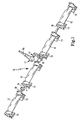
- a switching flap assembly 10 consists of a shaft 11, which is made for example of steel and are sprayed onto the switching flaps 12, for example made of plastic. These switching flaps are spaced apart, wherein between the switching flaps bearing blocks 13 are arranged made of plastic. Furthermore, an axial stop 14 is provided by means of which the shaft can be fixed axially at the installation location.
- a further functional unit 15 in the form of an articulated lever, which can be connected to a partially illustrated push rod 16 via a ball joint 17.
- a vacuum unit for example, by a vacuum unit, not shown, possible.
- Axial stop 14 and bearing blocks 13 are functional components in the context of the invention. These have bushings 18 through which the shaft 11 can be pushed. Since the bushings are closed, the functional components can be mounted only by sliding on the shaft from the end. Therefore, the sprayed-on switching flaps 12 prevent subsequent disassembly of the functional components.
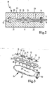
- FIG 2 a mold 19, consisting of an upper mold half 20 and a lower mold half 21 is shown. Between the two mold halves is a blank for a switching association consisting of the shaft 11 and the bearing blocks 13 (shown in simplified) inserted. Furthermore, cavities 22 can be seen in the mold, which can be filled via plastic 23 in the upper mold half 20 with plastic. This will the shaft 11 is encapsulated by the resulting switching flap, whereby the switching flap assembly is formed.
- the installation of a switching flap assembly according to the switching flap assembly 10 (here only with 3 switching flaps 12) in a suction pipe 24 is shown schematically in perspective in Figure 3.
- the joining direction is indicated by arrows 25.
- the switching flap assembly has as described bearing blocks 13 and a functional unit 15 in the form of the articulation crank.
- the entire switching assembly is installed in a receptacle 26 in the cylinder head flange 27.
- the switching flaps 12 communicate with suction channels 28 of the suction tube 24, which depart from a collecting space 29 together.
- the collecting space has a flange 30 for a throttle valve, not shown, of the intake tract for the internal combustion engine.
Description
- Die Erfindung betrifft ein Verfahren zur Herstellung eines Verbandes von Schaltklappen nach der Gattung des Patentanspruches 1.
- Der herzustellende Schaltklappenverband ist beispielsweise aus der WO 00/65214 bekannt. Es handelt sich hierbei um einen Schaltklappenverband, wie er in das Saugrohr einer Brennkraftmaschine eingebaut werden kann. Dieser besitzt gemäß der Ausführung gemäß der Figuren 3a, 3b eine einteilige Stahlwelle 32, auf die die Schaltklappen 15 montagegespritzt sind. Das Verfahren des Montagespritzens, beinhaltet weiterhin die Herstellung von Klappenrahmen 16 in derselben Spritzgußform, wie für die Schaltklappen 15 verwendet. Dies wird erreicht durch Öffnen einer Kavität mittels Schubkernen, wobei diese Kavität für die Schaltklappen 15 teilweise durch die Klappenrahmen 16 mitgebildet wird.
- Der beschriebene Schaltklappenverband läßt sich durch Verwendung des Montagespritzgießverfahrens sehr kostengünstig herstellen. Jedoch ist aufgrund der Anforderungen, dass der Schaltklappenverband nur in einer Form hergestellt werden soll, eine Herstellung geometrisch komplizierter Teile nicht möglich. Daher müssen sowohl die Klappenrahmen 16 als auch die Schaltklappen 15 eine einfache Geometrie aufweisen, wodurch zusätzliche Funktionen des Schaltklappenverbandes geometrisch nicht realisierbar sind.
- Aus der DE 197 17 347 ist ein Verfahren zum Herstellen einer Schaltklappe bekannt, wobei eine erste Hülse und eine zweite Hülse in einem vorgegebenen axialem Abstand auf eine Welle aufgebracht und radial verpresst werden. Die Welle wird zwischen der ersten und der zweiten Hülse mit einem thermoplastischen Grundstoff derart umspritzt, dass sich ein Flügelkörper bildet, der mindestens eine Aussparung aufweist.
- Es ist ferner aus der WO 96/316 92 ein Ansaugsystem bekannt, bei dem eine Schaltklappe in eine vorhandene Aussparung eingelegt wird und ein Dichtsystem vorgesehen ist, das im Bereich des Schaltklappenverbandes die Abdichtung des gesamten Systems zu einem Zwischenbauteil bewirkt. Der Schaltklappenverband weist relativ einfache Strukturen auf.
- Aus der FR 27 97 931 sind Schaltklappen zu entnehmen, die auf einer gemeinsamen Welle befestigt sind und in eine vorgesehene Ventilstruktur eingebaut werden. Auch diese Schaltklappen sind einfach aufgebaut und erfordern keine besonderen Einbaumaßnahmen.
- Aufgabe der Erfindung ist es daher, ein Verfahren für die Herstellung eines Schaltklappenverbandes zu schaffen, welches kostengünstig ist und die Realisierung komplizierter geometrischer Strukturen ermöglicht. Diese Aufgabe wird durch die Merkmale des Anspruches 1 gelöst.
- Das erfindungsgemäße Verfahren beinhaltet die Herstellung eines Verbandes von Schaltklappen auf einer gemeinsamen Welle, wobei die Klappen in Urformtechnik angeformt werden. Dies ist insbesondere durch Anspritzen von Kunststoffklappen an die Welle möglich. Jedoch sind auch andere urformtechnische Verfahren denkbar. Zum Beispiel können Metallklappen auf die Welle angegossen werden. Auch sintertechnische Verfahren sind vorstellbar.
- Gekennzeichnet ist das Verfahren durch die Anwendung der folgenden Verfahrensschritte.
- Es wird mindestens ein vorgefertigtes Funktionsbauteil auf die Welle aufgesteckt. Zu diesem Zweck ist das Funktionsbauteil mit einer Durchführung für die Welle versehen, wodurch ein Aufstecken nur ausgehend von einem der Wellenenden möglich ist, da die Durchführung für sich geschlossen hergestellt ist.
- Das Funktionsbauteil kann vorteilhafterweise mit beliebig komplexen Strukturen versehen werden. Beispielsweise lassen sich spritzgegossene Lagerböcke für die Welle auf selbige aufschieben. Diese können beispielsweise mit Entformungsrichtung genau senkrecht zur Entformungsrichtung der angespritzten Schaltklappen gestaltet, was entsprechend dem oben genannten Dokument des Standes der Technik nicht möglich ist. Auch können diese Funktionsbauteile mehrteilig aufgebaut sein um der Komplexität gerecht zu werden.
- Anschließend wird die Welle mit dem Funktionsbauteil zusammen in eine Form eingelegt, die die Herstellung der Schaltklappen zum Beispiel mittels Spritzgießen ermöglicht. Damit ist das Funktionsbauteil nach Herstellung der Klappen in den Klappenzwischenräumen auf der Welle gefangen, da aufgrund der Abmessungen der Schaltklappen ein Abziehen des Funktionsbauteils nicht mehr möglich ist. Das Herstellungsverfahren ist also Voraussetzung für die Herstellung eines Schaltklappenverbandes mit komplexer Struktur wobei die komplexen Strukturen durch die Funktionsbauteile gewährleistet werden.
- Weiterhin sieht die Erfindung vor, dass das Funktionsbauteil drehsteif auf der Welle arretiert wird. Dies ist für einen Anlenkhebel sinnvoll, der die Betätigungskraft beispielsweise einer Schubstange in ein Drehmoment an der Welle umwandeln soll.
- Den besagten Anlenkhebel ist in der Mitte der Welle vorgesehen. Auf diese Weise ist eine ausgewogene Kraftverteilung auf alle Schaltklappen möglich. Außerdem verringern sich auf diese Weise die Toleranzen während des Schaltvorgangs, die aufgrund einer Torsion der Welle zwischen den einzelnen Klappen auftreten können.
- Gemäß einer weiteren Ausbildung der Erfindung sind die Funktionsbauteile drehbar auf der Welle gelagert. Dies ist insbesondere dann von Bedeutung, wenn die Funktionsbauteile zur Lagerung der Welle im Einbauort verwendet werden.
- Eine weitere Ausgestaltung der Erfindung sieht vor, dass das Funktionsbauteil axial auf der Welle festgelegt wird. Hierbei ergibt sich eine einfachere Möglichkeit die Welle mit den vormontierten Funktionsbauteilen zu handhaben, da diese axial nicht verrutschen können. Hierdurch wird insbesondere das Einlegen der Welle in die Form erleichtert. Außerdem kann eine axiale Festlegung auch aufgrund funktionaler Aspekte erfolgen. Beispielsweise läßt sich auf diese Weise eine axiale Festlegung der Welle am Einbauort erreichen, um ein Scheuern der Schaltklappen in den zugehörigen Kanälen zu verhindern.
- Neben den Klappen kann gemäß einer weiteren Ausgestaltung der Erfindung auch eine andere Funktionseinheit an der Welle angeformt sein. Diese wird damit entsprechend den Klappen durch dasselbe oder ein anderes Formwerkzeug direkt an die Welle angespritzt. Hierfür eignet sich insbesondere ein Anlenkhebel, der eine Schaltkraft auf die Welle übertragen soll, wodurch das Schaltmoment für die Drehung der Schaltklappen zustande kommt.
- Diese und weitere Merkmale von bevorzugten Weiterbildungen der Erfindung gehen außer aus den Ansprüchen auch aus der Beschreibung und der Zeichnung hervor, wobei die einzelnen Merkmale jeweils für sich allein oder zu mehreren in Form von Unterkombinationen bei der Ausführungsform der Erfindung und auf anderen Gebieten verwirklicht sein und vorteilhafte sowie für sich schutzfähige Ausführungen darstellen können, für die hier Schutz beansprucht wird.
- Weitere Einzelheiten der Erfindung werden in der Zeichnung anhand von schematischen Ausführungsbeispielen beschrieben. Hierbei zeigen
- Figur 1
- einen gemäß dem erfindungsgemäßen Verfahren hergestellten Schaltverband als perspektivische Ansicht,
- Figur 2
- schematisch den Schaltverband in der Form im Schnitt vor dem Einspritzen des Klappenkunststoffes und
- Figur 3
- schematisch den Einbau des Schaltverbandes in ein Saugrohr in perspektivischer Ansicht.
- Ein Schaltklappenverband 10 besteht aus einer Welle 11, die beispielsweise aus Stahl gefertigt ist und auf der Schaltklappen 12 beispielsweise aus Kunststoff aufgespritzt sind. Diese Schaltklappen sind voneinander beabstandet, wobei zwischen den Schaltklappen Lagerböcke 13 aus Kunststoff angeordnet sind. Weiterhin ist ein Axialanschlag 14 vorgesehen, mit dessen Hilfe die Welle axial am Einbauort festgelegt werden kann.
- Ebenfalls angespritzt ist eine weitere Funktionseinheit 15 in Form eines Anlenkhebels, der mit einer teilweise dargestellten Schubstange 16 über ein Kugelgelenk 17 verbunden werden kann. Auf diese Weise wird die Steuerung des Schaltverbandes beispielsweise durch eine nicht dargestellte Unterdruckdose möglich.
- Axialanschlag 14 sowie Lagerböcke 13 sind Funktionsbauteile im Sinne der Erfindung. Diese weisen Durchführungen 18 auf durch welche die Welle 11 geschoben werden kann. Da die Durchführungen geschlossen sind, können die Funktionsbauteile lediglich durch Aufschieben auf die Welle vom Ende her montiert werden. Daher verhindern die aufgespritzten Schaltklappen 12 eine nachträgliche Demontage der Funktionsbauteile.
- In Figur 2 ist eine Form 19, bestehend aus einer oberen Formhälfte 20 und einer unteren Formhälfte 21 dargestellt. Zwischen die beiden Formhälften ist ein Rohling für einen Schaltverband, bestehend aus der Welle 11 und den Lagerböcken 13 (vereinfacht dargestellt) eingelegt. Weiterhin sind Kavitäten 22 in der Form zu erkennen, welche über Speiser 23 in der oberen Formhälfte 20 mit Kunststoff gefüllt werden können. Dadurch wird die Welle 11 durch die so entstehende Schaltklappe umspritzt, wodurch der Schaltklappenverband gebildet wird.
- Der Einbau eines Schaltklappenverbandes entsprechend dem Schaltklappenverband 10 (hier nur mit 3 Schaltklappen 12) in ein Saugrohr 24 ist schematisch perspektivisch in Figur 3 dargestellt. Die Fügerichtung ist durch Pfeile 25 angedeutet. Der Schaltklappenverband weist wie beschrieben Lagerböcke 13 und eine Funktionseinheit 15 in Form der Anlenkkurbel auf. Der gesamte Schaltverband wird in eine Aufnahme 26 im Zylinderkopfflansch 27 eingebaut. Die Schaltklappen 12 kommunizieren dabei mit Saugkanälen 28 des Saugrohres 24, welche gemeinsam von einem Sammelraum 29 abgehen. Der Sammelraum besitzt einen Flansch 30 für eine nicht dargestellte Drosselklappe des Ansaugtraktes für die Brennkraftmaschine.
Claims (5)
- Verfahren zur Herstellung eines Verbandes von Schaltklappen (12) auf einer gemeinsamen Welle (11), indem die Schaltklappen an die Welle in Urformtechnik angeformt werden, gekennzeichnet durch die Verfahrensschritte in der angegebenen Reihenfolge, dass- mindestens ein vorgefertigtes Funktionsbauteil (13, 14) auf die Welle aufgesteckt wird, welches zu diesem Zweck mit einer geschlossenen Durchführung (18) für die Welle versehen ist,- die Welle (11) mit dem Funktionsbauteil (13, 14) in eine Form (19) eingelegt wird,- die Schaltklappen (12) mittels der Form (19) hergestellt werden, derart, dass das mindestens eine Funktionsbauteil (13, 14) sich zwischen zwei Schaltklappen (12) befindet, wobei diese eine Demontage des Funktionsbauteils verhindern dass eine weitere Funktionseinheit (15) in Form eines Anlenkhebels an die Welle (11) angeformt wird, wobei der Anlenkhebel in der Mitte der Welle (11) zwischen zwei Schaltklappen (12) angeordnet ist.
- Verfahren nach Anspruch 1, dadurch gekennzeichnet, dass das mindestens eine Funktionsbauteil (13, 14) drehbar auf der Welle gelagert ist und insbesondere als Lagerbock ausgeführt ist.
- Verfahren nach Anspruch 1, dadurch gekennzeichnet, dass das Funktionsbauteil (13, 14) auf der Welle drehsteif arretiert wird.
- Verfahren nach einem der vorherigen Ansprüche, dadurch gekennzeichnet, dass das Funktionsbauteil (13, 14) axial auf der Welle festgelegt wird.
- Verfahren nach einem der vorherigen Ansprüche, dadurch gekennzeichnet, dass außer den Klappen auch eine andere Funktionseinheit (15) an die Welle angeformt wird.
Applications Claiming Priority (2)
| Application Number | Priority Date | Filing Date | Title |
|---|---|---|---|
| DE10131109 | 2001-06-27 | ||
| DE10131109A DE10131109A1 (de) | 2001-06-27 | 2001-06-27 | Verfahren zur Herstellung eines Schaltklappenverbandes |
Publications (3)
| Publication Number | Publication Date |
|---|---|
| EP1270904A2 EP1270904A2 (de) | 2003-01-02 |
| EP1270904A3 EP1270904A3 (de) | 2004-07-28 |
| EP1270904B1 true EP1270904B1 (de) | 2006-11-08 |
Family
ID=7689716
Family Applications (1)
| Application Number | Title | Priority Date | Filing Date |
|---|---|---|---|
| EP02013227A Expired - Lifetime EP1270904B1 (de) | 2001-06-27 | 2002-06-15 | Verfahren zur Herstellung eines Schaltklappenverbandes |
Country Status (5)
| Country | Link |
|---|---|
| US (1) | US6692675B2 (de) |
| EP (1) | EP1270904B1 (de) |
| JP (1) | JP4368094B2 (de) |
| AT (1) | ATE344877T1 (de) |
| DE (2) | DE10131109A1 (de) |
Families Citing this family (7)
| Publication number | Priority date | Publication date | Assignee | Title |
|---|---|---|---|---|
| EP1239132A1 (de) * | 2001-03-05 | 2002-09-11 | Dsm N.V. | Drosselklappenstutzen aus thermoplastischem Material |
| DE102004005480B4 (de) * | 2004-02-04 | 2013-10-17 | GM Global Technology Operations LLC (n. d. Ges. d. Staates Delaware) | Schaltklappe für Saugrohr |
| DE102005029798B4 (de) * | 2005-06-27 | 2015-02-05 | Volkswagen Ag | Schaltbauteil für ein Saugrohr einer Brennkraftmaschine |
| JP2007138840A (ja) * | 2005-11-18 | 2007-06-07 | Denso Corp | 吸気装置およびその製造方法 |
| FR2960806B1 (fr) * | 2010-06-04 | 2012-06-22 | Mann & Hummel Gmbh | Procede de fabrication d'un assemblage de soupapes a clapet pour un collecteur d'admission d'air et assemblage realise |
| KR101147823B1 (ko) * | 2011-01-07 | 2012-05-21 | 주식회사 이파그리드코리아 | 지오그리드와 지오그리드 제조장치 및 제조장치를 이용한 지오그리드 제조방법 |
| WO2017210169A1 (en) * | 2016-06-01 | 2017-12-07 | Synventive Molding Solutions, Inc. | Controller arrangement for injection molding system |
Family Cites Families (22)
| Publication number | Priority date | Publication date | Assignee | Title |
|---|---|---|---|---|
| US3707032A (en) * | 1969-01-23 | 1972-12-26 | Weatherhead Co | Method of forming an abrasion resistant hose assembly |
| DE2063369C3 (de) * | 1970-12-23 | 1975-04-24 | Daimler-Benz Ag, 7000 Stuttgart | Lagerung einer Heizklappe im Auspuffleitungssystem einer Brennkraftmaschine |
| US4198368A (en) * | 1973-07-03 | 1980-04-15 | Imperial Chemical Industries Limited | Valve |
| US4914711A (en) * | 1981-07-23 | 1990-04-03 | Polaroid Corporation | Integrally molded bearing block assembly |
| US5049341A (en) * | 1981-07-23 | 1991-09-17 | Polaroid Corporation | Integrally molded bearing block assembly |
| US4477406A (en) * | 1981-09-22 | 1984-10-16 | Deere & Company | Method for molding elongated workpieces |
| JPS6077731U (ja) * | 1983-11-01 | 1985-05-30 | マツダ株式会社 | エンジンの吸気装置 |
| US4671746A (en) * | 1984-06-25 | 1987-06-09 | Applied Power Inc. | Base component for a fluid transfer device and method of making the component |
| US5041253A (en) * | 1987-10-01 | 1991-08-20 | Husted Royce Hill | Method of making a plastic stabilized composite camshaft |
| JPH07137179A (ja) * | 1993-07-19 | 1995-05-30 | Xerox Corp | 2つの部材を移動可能に連結した組立体を製造する方法 |
| DE4334180A1 (de) * | 1993-10-07 | 1995-04-13 | Bosch Gmbh Robert | Drosselvorrichtung |
| DE4343091A1 (de) * | 1993-12-17 | 1995-06-22 | Bosch Gmbh Robert | Drosselvorrichtung, insbesondere für eine Brennkraftmaschine, und Verfahren zum Herstellen einer Drosselvorrichtung |
| KR100222527B1 (ko) * | 1994-11-24 | 1999-10-01 | 정몽규 | 내연기관의 흡기조절장치 |
| JP3375017B2 (ja) * | 1994-12-20 | 2003-02-10 | 株式会社デンソー | スロットル弁制御装置 |
| JPH08277717A (ja) * | 1995-04-06 | 1996-10-22 | Du Pont Kk | 吸気制御バルブを備えた樹脂吸気系 |
| DE19615438A1 (de) * | 1995-07-17 | 1997-01-23 | Mann & Hummel Filter | Ventil |
| US5715782A (en) * | 1996-08-29 | 1998-02-10 | Genral Motors Corporation | Composite molded butterfly valve for an internal combustion engine |
| DE19717350A1 (de) * | 1997-03-07 | 1998-09-24 | Siemens Ag | Schaltklappe |
| JP4178642B2 (ja) * | 1998-02-04 | 2008-11-12 | 日産自動車株式会社 | 空気流量制御装置及びその製造方法 |
| DE19918777A1 (de) * | 1999-04-24 | 2000-10-26 | Mann & Hummel Filter | Schaltklappenverband aus montagegespritzten Schaltklappen oder Klappenmodulen |
| US6263917B1 (en) * | 1999-08-12 | 2001-07-24 | Delphi Technologies, Inc. | Multiple-bore throttle valve having central shaft end-play restraint |
| FR2797931B1 (fr) * | 1999-08-31 | 2001-10-05 | Mark Iv Systemes Moteurs Sa | Dispositif de regulation de l'ecoulement dans une portion de conduit ou un passage et collecteur comprenant un tel dispositif |
-
2001
- 2001-06-27 DE DE10131109A patent/DE10131109A1/de not_active Withdrawn
-
2002
- 2002-06-15 EP EP02013227A patent/EP1270904B1/de not_active Expired - Lifetime
- 2002-06-15 DE DE50208639T patent/DE50208639D1/de not_active Expired - Lifetime
- 2002-06-15 AT AT02013227T patent/ATE344877T1/de not_active IP Right Cessation
- 2002-06-25 US US10/178,778 patent/US6692675B2/en not_active Expired - Lifetime
- 2002-06-26 JP JP2002186685A patent/JP4368094B2/ja not_active Expired - Fee Related
Also Published As
| Publication number | Publication date |
|---|---|
| US6692675B2 (en) | 2004-02-17 |
| US20030009881A1 (en) | 2003-01-16 |
| DE50208639D1 (de) | 2006-12-21 |
| ATE344877T1 (de) | 2006-11-15 |
| JP2003039252A (ja) | 2003-02-12 |
| DE10131109A1 (de) | 2003-01-09 |
| EP1270904A3 (de) | 2004-07-28 |
| EP1270904A2 (de) | 2003-01-02 |
| JP4368094B2 (ja) | 2009-11-18 |
Similar Documents
| Publication | Publication Date | Title |
|---|---|---|
| EP1175556B1 (de) | Schaltklappenverband aus montagegespritzten schaltklappen oder klappenmodulen | |
| EP1521893B1 (de) | Verschluss mit zwei riegelstangen, insbesondere für fahrzeuge | |
| EP1802877B1 (de) | Nachgiebige buchsenanordnung | |
| WO2000023701A1 (de) | Klappenmechanismus | |
| DE4322586A1 (de) | Betätigungsvorrichtung für eine Schiebemuffe in einem Kraftfahrzeug-Stufengetriebe | |
| EP3722641A1 (de) | Planetenträgeranordnung eines planetengetriebes, insbesondere eines planetengetriebes eines seitentürantriebes, sowie verfahren zum herstellen einer derartigen planetenträgeranordnung | |
| EP1270904B1 (de) | Verfahren zur Herstellung eines Schaltklappenverbandes | |
| EP0747587A1 (de) | Einrichtung zur Einstellung der Rohrlänge von Saugrohren und Verfahren zu deren Herstellung | |
| EP1420938B1 (de) | Verfahren zur herstellung eines drosselklappenstutzengehäuses und einer drosselklappe | |
| EP1826375B1 (de) | Schaltventil und zugehöriges Herstellungsverfahren | |
| DE4241409C2 (de) | Verfahren sowie Vorrichtung zum Herstellen eines Bauteils durch Spritzen wenigstens zweier Elemente aus Kunststoff und durch Zusammenfügen dieser Elemente nach dem Spritzen | |
| DE60303544T2 (de) | Herstellungsverfahren für das Rotorkomponent eines Positionsgebers eines Drehklappenventils für eine Brennkraftmaschine | |
| EP1419330B1 (de) | Drosselklappenstutzen für einen verbrennungsmotor | |
| DE3606073C2 (de) | Drehgelenk | |
| WO2022112525A1 (de) | Schiebenockenwellenanordnung für eine brennkraftmaschine, sowie verfahren zum schalten einer schiebenockenwellenanordnung für eine brennkraftmaschine | |
| EP1563174B1 (de) | Verfahren zur herstellung eines drosselklappenstutzens | |
| EP1517776B1 (de) | Verfahren zur herstellung einer drosselklappe in einem durchgehenden drosselklappenstutzen durch spritzgiessen von kunststoff | |
| DE102007027844A1 (de) | Verfahren zur Herstellung eines Verbundbauteils und Verbundbauteil, das mit einer Handhabe zur Bewegung eines beweglichen Teils koppelbar ist | |
| EP0280774B1 (de) | Steuerwellenantrieb für eine Hubkolbenbrennkraftmaschine | |
| EP1447603A2 (de) | Drosselklappe und Verfahren zu deren Herstellung | |
| EP1991406B1 (de) | Spritzgussverfahren zur herstellung eines bauteils mit wenigstens zwei gesondert voneinander und relativ zueinander beweglich ausgebildeten funktionskomponenten | |
| WO1997013060A1 (de) | Ansauganlage für eine mehrzylinderbrennkraftmaschine | |
| DE4014143C2 (de) | ||
| EP2064047B1 (de) | Verfahren und spritzwerkzeug zur herstellung eines ansaugtraktes aus kunststoff für verbrennungsmotoren sowie hergestellter ansaugtrakt | |
| DE102006034705A1 (de) | Verfahren zum Herstellen eines Wischarmes sowie Wischarm |
Legal Events
| Date | Code | Title | Description |
|---|---|---|---|
| PUAI | Public reference made under article 153(3) epc to a published international application that has entered the european phase |
Free format text: ORIGINAL CODE: 0009012 |
|
| AK | Designated contracting states |
Kind code of ref document: A2 Designated state(s): AT BE CH CY DE DK ES FI FR GB GR IE IT LI LU MC NL PT SE TR |
|
| AX | Request for extension of the european patent |
Free format text: AL;LT;LV;MK;RO;SI |
|
| RAP1 | Party data changed (applicant data changed or rights of an application transferred) |
Owner name: MANN + HUMMEL GMBH |
|
| PUAL | Search report despatched |
Free format text: ORIGINAL CODE: 0009013 |
|
| AK | Designated contracting states |
Kind code of ref document: A3 Designated state(s): AT BE CH CY DE DK ES FI FR GB GR IE IT LI LU MC NL PT SE TR |
|
| AX | Request for extension of the european patent |
Extension state: AL LT LV MK RO SI |
|
| 17P | Request for examination filed |
Effective date: 20040831 |
|
| 17Q | First examination report despatched |
Effective date: 20041117 |
|
| AKX | Designation fees paid | ||
| REG | Reference to a national code |
Ref country code: DE Ref legal event code: 8566 |
|
| RBV | Designated contracting states (corrected) |
Designated state(s): AT BE CH CY DE DK ES FI FR GB GR IE IT LI LU MC NL PT SE TR |
|
| GRAP | Despatch of communication of intention to grant a patent |
Free format text: ORIGINAL CODE: EPIDOSNIGR1 |
|
| GRAS | Grant fee paid |
Free format text: ORIGINAL CODE: EPIDOSNIGR3 |
|
| GRAA | (expected) grant |
Free format text: ORIGINAL CODE: 0009210 |
|
| AK | Designated contracting states |
Kind code of ref document: B1 Designated state(s): AT BE CH CY DE DK ES FI FR GB GR IE IT LI LU MC NL PT SE TR |
|
| PG25 | Lapsed in a contracting state [announced via postgrant information from national office to epo] |
Ref country code: FI Free format text: LAPSE BECAUSE OF FAILURE TO SUBMIT A TRANSLATION OF THE DESCRIPTION OR TO PAY THE FEE WITHIN THE PRESCRIBED TIME-LIMIT Effective date: 20061108 Ref country code: NL Free format text: LAPSE BECAUSE OF FAILURE TO SUBMIT A TRANSLATION OF THE DESCRIPTION OR TO PAY THE FEE WITHIN THE PRESCRIBED TIME-LIMIT Effective date: 20061108 Ref country code: IE Free format text: LAPSE BECAUSE OF FAILURE TO SUBMIT A TRANSLATION OF THE DESCRIPTION OR TO PAY THE FEE WITHIN THE PRESCRIBED TIME-LIMIT Effective date: 20061108 |
|
| REG | Reference to a national code |
Ref country code: GB Ref legal event code: FG4D Free format text: NOT ENGLISH |
|
| REG | Reference to a national code |
Ref country code: CH Ref legal event code: EP |
|
| REG | Reference to a national code |
Ref country code: IE Ref legal event code: FG4D Free format text: LANGUAGE OF EP DOCUMENT: GERMAN |
|
| REF | Corresponds to: |
Ref document number: 50208639 Country of ref document: DE Date of ref document: 20061221 Kind code of ref document: P |
|
| PG25 | Lapsed in a contracting state [announced via postgrant information from national office to epo] |
Ref country code: SE Free format text: LAPSE BECAUSE OF FAILURE TO SUBMIT A TRANSLATION OF THE DESCRIPTION OR TO PAY THE FEE WITHIN THE PRESCRIBED TIME-LIMIT Effective date: 20070208 Ref country code: DK Free format text: LAPSE BECAUSE OF FAILURE TO SUBMIT A TRANSLATION OF THE DESCRIPTION OR TO PAY THE FEE WITHIN THE PRESCRIBED TIME-LIMIT Effective date: 20070208 |
|
| PG25 | Lapsed in a contracting state [announced via postgrant information from national office to epo] |
Ref country code: ES Free format text: LAPSE BECAUSE OF FAILURE TO SUBMIT A TRANSLATION OF THE DESCRIPTION OR TO PAY THE FEE WITHIN THE PRESCRIBED TIME-LIMIT Effective date: 20070219 |
|
| GBT | Gb: translation of ep patent filed (gb section 77(6)(a)/1977) |
Effective date: 20070129 |
|
| PG25 | Lapsed in a contracting state [announced via postgrant information from national office to epo] |
Ref country code: PT Free format text: LAPSE BECAUSE OF FAILURE TO SUBMIT A TRANSLATION OF THE DESCRIPTION OR TO PAY THE FEE WITHIN THE PRESCRIBED TIME-LIMIT Effective date: 20070409 |
|
| NLV1 | Nl: lapsed or annulled due to failure to fulfill the requirements of art. 29p and 29m of the patents act | ||
| ET | Fr: translation filed | ||
| REG | Reference to a national code |
Ref country code: IE Ref legal event code: FD4D |
|
| PLBE | No opposition filed within time limit |
Free format text: ORIGINAL CODE: 0009261 |
|
| STAA | Information on the status of an ep patent application or granted ep patent |
Free format text: STATUS: NO OPPOSITION FILED WITHIN TIME LIMIT |
|
| 26N | No opposition filed |
Effective date: 20070809 |
|
| BERE | Be: lapsed |
Owner name: MANN + HUMMEL G.M.B.H. Effective date: 20070630 |
|
| PG25 | Lapsed in a contracting state [announced via postgrant information from national office to epo] |
Ref country code: MC Free format text: LAPSE BECAUSE OF NON-PAYMENT OF DUE FEES Effective date: 20070630 |
|
| REG | Reference to a national code |
Ref country code: CH Ref legal event code: PL |
|
| PG25 | Lapsed in a contracting state [announced via postgrant information from national office to epo] |
Ref country code: BE Free format text: LAPSE BECAUSE OF NON-PAYMENT OF DUE FEES Effective date: 20070630 |
|
| PG25 | Lapsed in a contracting state [announced via postgrant information from national office to epo] |
Ref country code: GR Free format text: LAPSE BECAUSE OF FAILURE TO SUBMIT A TRANSLATION OF THE DESCRIPTION OR TO PAY THE FEE WITHIN THE PRESCRIBED TIME-LIMIT Effective date: 20070209 Ref country code: LI Free format text: LAPSE BECAUSE OF NON-PAYMENT OF DUE FEES Effective date: 20070630 Ref country code: CH Free format text: LAPSE BECAUSE OF NON-PAYMENT OF DUE FEES Effective date: 20070630 |
|
| PG25 | Lapsed in a contracting state [announced via postgrant information from national office to epo] |
Ref country code: AT Free format text: LAPSE BECAUSE OF NON-PAYMENT OF DUE FEES Effective date: 20070615 |
|
| PG25 | Lapsed in a contracting state [announced via postgrant information from national office to epo] |
Ref country code: CY Free format text: LAPSE BECAUSE OF FAILURE TO SUBMIT A TRANSLATION OF THE DESCRIPTION OR TO PAY THE FEE WITHIN THE PRESCRIBED TIME-LIMIT Effective date: 20061108 Ref country code: LU Free format text: LAPSE BECAUSE OF NON-PAYMENT OF DUE FEES Effective date: 20070615 |
|
| PG25 | Lapsed in a contracting state [announced via postgrant information from national office to epo] |
Ref country code: TR Free format text: LAPSE BECAUSE OF FAILURE TO SUBMIT A TRANSLATION OF THE DESCRIPTION OR TO PAY THE FEE WITHIN THE PRESCRIBED TIME-LIMIT Effective date: 20061108 |
|
| PGFP | Annual fee paid to national office [announced via postgrant information from national office to epo] |
Ref country code: GB Payment date: 20120622 Year of fee payment: 11 |
|
| GBPC | Gb: european patent ceased through non-payment of renewal fee |
Effective date: 20130615 |
|
| PG25 | Lapsed in a contracting state [announced via postgrant information from national office to epo] |
Ref country code: GB Free format text: LAPSE BECAUSE OF NON-PAYMENT OF DUE FEES Effective date: 20130615 |
|
| REG | Reference to a national code |
Ref country code: FR Ref legal event code: PLFP Year of fee payment: 15 |
|
| PGFP | Annual fee paid to national office [announced via postgrant information from national office to epo] |
Ref country code: IT Payment date: 20160628 Year of fee payment: 15 |
|
| REG | Reference to a national code |
Ref country code: FR Ref legal event code: PLFP Year of fee payment: 16 |
|
| PG25 | Lapsed in a contracting state [announced via postgrant information from national office to epo] |
Ref country code: IT Free format text: LAPSE BECAUSE OF NON-PAYMENT OF DUE FEES Effective date: 20170615 |
|
| REG | Reference to a national code |
Ref country code: FR Ref legal event code: PLFP Year of fee payment: 17 |
|
| REG | Reference to a national code |
Ref country code: DE Ref legal event code: R081 Ref document number: 50208639 Country of ref document: DE Owner name: MANN+HUMMEL GMBH, DE Free format text: FORMER OWNER: MANN + HUMMEL GMBH, 71638 LUDWIGSBURG, DE |
|
| PGFP | Annual fee paid to national office [announced via postgrant information from national office to epo] |
Ref country code: DE Payment date: 20200618 Year of fee payment: 19 Ref country code: FR Payment date: 20200619 Year of fee payment: 19 |
|
| REG | Reference to a national code |
Ref country code: DE Ref legal event code: R119 Ref document number: 50208639 Country of ref document: DE |
|
| PG25 | Lapsed in a contracting state [announced via postgrant information from national office to epo] |
Ref country code: DE Free format text: LAPSE BECAUSE OF NON-PAYMENT OF DUE FEES Effective date: 20220101 |
|
| PG25 | Lapsed in a contracting state [announced via postgrant information from national office to epo] |
Ref country code: FR Free format text: LAPSE BECAUSE OF NON-PAYMENT OF DUE FEES Effective date: 20210630 |